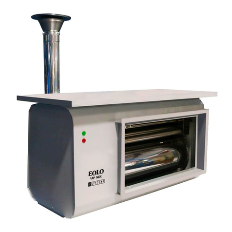
Systema EOLO G GE Series User manual

SYSTEMA
EOLO G
Rev. 01EN18-04
1
Rev
.
01EN18-04
DIESEL OIL AIRTHIGHT SUSPENDED WARM AIR HEATERS
EOLO G
GE/GC
USER MANUAL
INSTALLATION, USE AND MAINTENANCE

SYSTEMA
EOLO G
Rev. 01EN18-04
2
IMPORTANT: Read this manual carefully before starting up the system. In order to improve
the product, Systema reserves the right to modify the content without prior notice.
Appliance subject to periodic maintenance, depending on the type of fuel,
specific applications, room temperature, length of use etc.
Długa 5
Zduńska Wola 98-220
POLAND
Tel +48438247287
E-mail: systema@systemapolska.pl
http://www.systemapolska.pl

SYSTEMA
EOLO G
Rev. 01EN18-04
3
SUMMARY
1 GENERAL RULES...........................................................................................5
1.1 TECHNICAL SPECIFICATIONS.................................................................................... 6
1.2 TECHNICAL DATA.......................................................................................................6
1.3 DIMENSIONS................................................................................................................6
1.3.1 Eolo GE -axial fans ........................................................................................................................7
1.3.2 Eolo GC-centrifugal fans ...............................................................................................................8
1.3.3 Exploded view of EOLO heater......................................................................................................9
1.3.4 Eolo GE -axial fans ........................................................................................................................9
1.3.5 Eolo GC-centrifugal fans .............................................................................................................10
2 ELECTRICAL DIAGRAM EOLO GE - GC.....................................................11
3 BURNER - FUEL CONNECTION...................................................................12
4 INSTALLATION..................................................................................................12
4.1 WALL INSTALLATION....................................................................................................13
4.2 EXAMPLE OF INSTALLA TION EOLO CENTRIFUGAL..............................................14
5 FUMES / AIR INTAKE INSTALLATION...........................................................15
5.1 FUMES / AIR TERMINALS TYPE C13 HORIZONTAL ............................................... 16
5.2 FUMES TERMINALS TYPE B23HORIZONTAL ........................................................ 16
5.3 FUMES / AIR TERMINALS TYPE C33 VERTICAL..................................................... 17
5.4 FUMES TERMINALS TYPE B23VERTICAL.............................................................. 17
6 START UP OF HEATER................................................................................18
6.1 PRELIMINAR OPERATIONS ..................................................................................... 18
7 WARRANTY...................................................................................................19
7.1 SUBJECT - MATTER AND DURATION OF THE WARRANTY.................................. 19
7.2 EXCLUSIONS FROM THE WARRANTY.................................................................... 19
7.3 COMPETENCE .......................................................................................................... 19
7.4 RESPONSABILITY..................................................................................................... 19
8 SETING ASIDE ..................................................................................................19

SYSTEMA
EOLO G
Rev. 01EN18-04
4
1 GENERAL RULES
The present instruction manual is an integral and essential part of the appliance and must be kept
carefully beside the appliance for further consultation.
Read the instructions and warnings contained in this manual carefully as they provide important
information on safety, installation, use and maintenance.
ATTENTION!!
In the event of this manual being misplaced contact the manufacturer immediately.
Several appliances installed in the same room or in directly communicating rooms, are considered
as a single system, with a thermal capacity of the total of the thermal capacities of each single
appliance.
Their use is not permitted to heat rooms destined for handicraft or industrial activities in which
processes and materials stored may cause the formation of , vapours or powder susceptible to
induce fires or explosions.
The installation must be perfomed by professionally qualified personnel responsible for compliance
with the current safety standards. The manufacturer declines all responsability in the event of damages
caused by erroneous installation or improper and/or of the appliance.
The packaging materials (nylon, foamed polystyrene, wood, staples, etc…) must not be left within
the reach of children as they are potential sources of danger and pollution , but they must be collected
and stored in a proper area.
Initial ignition of the appliance must be performed by professionally qualified personnel.
In the case of the appliance shutting down or functioning incorrectly it must be switched off. Any
repairs or replacement of spare parts must be performed solely by qualified personnel using exclusively
original spare parts. Non-compliance with the aforesaid rules may endager the safety of the appliances.
To guarantee correct operation of the appliance it is fundamental to carefully follow the instructions
provided by manufacturer and to have the appliance serviced by qualified personnel at least once a
year.
N.B. To switch off the appliance always used the ambient thermostat and not the master switch on
the control board on the ground, as this could cause over-heating in the combustion chamber with
consequent damage to the appliance.
In the event of ownership change or new lodger, it must deliver all documentation about the heating
system to the new owner or lodger.
The heater should be installed indoor.

SYSTEMA
EOLO G
Rev. 01EN18-04
5
1.1 TECHNICAL SPECIFICATIONS
EOLO G…Oil burner version GE - axial fan and GC - centrifugal fan
1.2 TECHNICAL DATA
EOLO
25 GE/GC
35 GE/GC
45 GE/GC
55 GE/GC
65 GE/GC
85 GE/GC
100 GE/GC
Thermal load
kW
22
32
42
50
62
80
101
Combustion performance
%
91
92
92
92
92
92
92
Emision CO
Mg/kWh
30
25
20
Emision NOx
Mg/kWh
220
180
170
Thermal load used
kW
20
29.5
27.6
46
57
73.6
92.9
Fuel
-
Light oil
Fuel connector diameter
"
½ + ½
Oil burner model [one stage]
Riello
RG 0.3
RG 1
RG 2
Total electric power required
mod.GE
W
260
350
560
710
690
1120
1480
Max oil consumption
kg/h
1,85
2,87
4,55
5,9
7,93
9,7
11,8
Alimentazione elettrica
230 V. +/- 50 Hz.
Total electric power required
mod. GE
W
260
350
560
410
690
1 120
1 480
Total electric power required
mod. GC
W
540
580
1 120
1 140
1 160
2 260
2 580
Treated air capacity GE
m3h.
2 900
3 600
4 500
5 600
7 000
8 100
11 000
Treated air capacity GC
m3h.
2 200
2 800
4 000
5 100
5 800
8 100
9 600
No. of ventilators GE/GC
Nr.
1/1
1/1
1/1
1/1
2/2
2/2
2/2
Air throw GE
m.
13
17
19
23
25
27
30
Usefull pressure mod. GC
(standard)
Pa
110
120
110
110
110
120
120
Thermal Jump (standard)
°C
28-30
Fume outlet diameter / air
intake
mm.
100 / 100
130 / 130
Type of instalation
B 23 –C 13 –C33 –C 53
Work temperature
°C
0 / 30
Sound level (at 5 mt)
dBA
51
52
57
58
59
60
61
Waight GE
Kg.
69
75
89
118
128
192
212
Waight GC
Kg.
75
86
102
136
148
212
236
Tab 1.1 technical data

SYSTEMA
EOLO G
Rev. 01EN18-04
6
1.3 DIMENSIONS
1.3.1 Eolo GE- Axial fan
Fig 1.1 Dimensions Eolo GE series
Dimensions Eolo GE
MODEL
G1
G2
G3
G4
A1
A2
A5
A6
B1
B2
S1
S2
Weight
EOLO 25 GE
854
620
655
535
475
322
255
95
350
450
232
648
69
EOLO 35 GE
1095
620
655
535
475
322
255
95
350
750
232
887
75
EOLO 45 GE
1155
740
710
600
600
300
285
145
450
750
320
875
89
EOLO 55 GE
1290
740
710
600
600
300
285
145
450
850
320
990
118
EOLO 65 GE
1440
840
840
720
675
324
290
180
500
900
332
1164
128
EOLO 85 GE
1600
840
840
720
675
324
335
160
500
1000
332
1324
192
EOLO 100 GE
1750
840
840
720
675
324
335
160
500
1150
332
1489
212
Tab 1.3

SYSTEMA
EOLO G
Rev. 01EN18-04
7
1.3.2 Eolo GC- centrifugal fan
Fig 1.2 Dimensioni Eolo GC - serie centrifuga
Dimensions Eolo GC
MODEL
G1
G2
G3
G4
A1
A2
A5
A6
B1
B2
S1
S2
Weight
EOLO 25 GC
854
620
655
535
475
322
255
95
350
450
232
648
75
EOLO 35 GC
1095
620
655
535
475
322
255
95
350
750
232
887
86
EOLO 45 GC
1155
740
710
600
600
300
285
145
450
750
320
875
102
EOLO 55 GC
1290
740
710
600
600
300
285
145
450
850
320
990
136
EOLO 65 GC
1440
840
840
720
675
324
290
180
500
900
332
1164
148
EOLO 85 GC
1600
840
840
720
675
324
335
160
500
1000
332
1324
212
EOLO 100 GC
1750
840
840
720
675
324
335
160
500
1150
332
1489
236
Tab 1.4

SYSTEMA
EOLO G
Rev. 01EN18-04
8
1.3.3 Exploded view of Eolo heater
1.3.4 Eolo GE- axial fan
Fig 1.3
Pos
Descripti
on
Pos
Descrizione
1
Front panel
9
Back panel - fan support
2
Supply air grille with horizontal fins
9a
support with 1 axial fan
3
Thermal isolation
9b
support with 2 axial fans
4
Internal panel
17
top closing panel
5
Double thermostat with STB
18
Base panel
6
Burner RIELLO
19
Heat exchanger with combustion chamberposteriore
7
Side door panel
19a
Inspection of heat exchanger
8
Electrical terminal connection
20
Side panel
Tab 1.5 Explode Eolo GE -axialfanseries

SYSTEMA
EOLO G
Rev. 01EN18-04
9
1.3.5 Eolo GC - serie centrifuga
Fig 1.4
No.
Description
No.
Description
1
Front panel
9
Back panel - fan support
2
Supply air grille with horizontal fins
9a
support with 1 centrifugal fan
3
Thermal isolation
9b
support with 2 centrifugal fans
4
Internal panel
17
top closing panel
5
Double thermostat with STB
18
Base panel
6
Burner RIELLO
19
Heat exchanger with combustion chamberposteriore
7
Side door panel
19a
Inspection of heat exchanger
8
Electrical terminal connection
20
Side panel
Tab 1.6 Esploso Eolo GC serie centrifuga

SYSTEMA
EOLO G
Rev. 01EN18-04
10
2 ELECTRICAL DIAGRAM EOLO GE - GC
No.
Description
1
7 POLS SOCK RIELLO BURNER
2
THERMOSTAT OF VENTILATION –SAFETY THERMOSTAT
3
FAN CONNECTION - Connectors 10 FASE –11 NEUTRO –12 GROUND
4
ELECTRICAL CONNECTORS
Alimentazione elettrica 230 V. 50 hz. 1F connettori PE-L1-N
5
AMBIENT THERMOSTAT Connectors 1-2
6
ADDITIONAL SAFETY Connectors 6-7
7
MANUAL TURNING OPERATION OF FANS (SUMMER VENTILATION) Connettori 8-9
8
WARKING / ALARM LIGHT Connectors 3 neutro-com 4 fase/warking - 6 fase / alarm burner light
9
WARKING / ALARM LIGHT - on the front panel
10
FUSES

SYSTEMA
EOLO G
Rev. 01EN18-04
11
3 BURNER - FUEL CONNECTION
The supply combustible system must complied to the scheme in additional instruction manual of Riello burner.
ALL THE MAINTENANCE OPERATIONS MUST BE PERFORMED FROM TECHNICAL SPECIALISED PERSONNEL.
4 INSTALLATION
To obtain the maximum performance from the "EOLO" suspended warm air
heaters you must follow this rules:
- Established the position, bearing in mind the type of work, priority
zones to be heated and absorbing walls (windows, doors, entrances
etc.) see fig. (4.1, 4.2, 4.3).
- install the appliances respecting the correct distances from the walls
see fig. (5d, 5e)
- install the suspended hot air heaters "EOLO" as near as possible to
the area to be heated complying with a distance from the floor and
from the people to ensure the jet of warm air is not aimed directly at
them.
- When positioning the "EOLO" suspended hot air heaters take into
account any obstacles, such as shelves, walls, columns, etc.
- if several appliances are to be installed in the same environment it
is advisable to position these on opposite walls and between one
another to cover the area to be heated uniformly. In order to uniform
the area to be heated uniformly
- if there are any drafts of cold air from entrances, doors, etc. it is
advisable to install the appliances so that the jet of hot air is aimed
towards the source of cold air.
- the appliance installation mustn't be made in positions or niches that
not guarantee sufficient aeration for the good working.
- several appliances installed in the same area or in directly
communicating areas, are considered as a single system, with a
thermal capacity of the total of the thermal capacities of each single
appliance.
- installation must be performed by professionally qualified personnel
responsible for complying with the current safety standards. The
manufacturer declines all responsibility in the case of damage
caused by erroneous installation or improper and/or incorrect use of
the appliance
Fig.4.1
Fig.4.3
Fig.4.

SYSTEMA
EOLO G
Rev. 01EN18-04
12
4.1 WALL INSTALLATION
The Eolo GE - GC heater can be fixed to the wall of the building. Using one of the solutions shown in the
following figures..
Fig.4.6 Mounting wall bracket
ATTENTION!!
TO INSTALL EOLO IN SUSPENSION,IT IS NECESSARY TO SPECIFY THE ORDER CONFIGURATION.
The manufacturer declines all responsibility in case of damages due to incorrect installation or improper and / or
incorrect use of the appliance .
Fig.4.7 Example of wall mounting Eolo GC / GE series with brackets: A - in support, B - in suspension

SYSTEMA
EOLO G
Rev. 01EN18-04
13
4.2 EXAMPLE OF INSTALTION EOLO CENTRIFUGAL
The following figures show an example of the installation of centrifugal Eolo series, installed inside with air
duct. Air intake takes place both from the outside and inside with the possibility of adjusting the internal /
external air mixture.
Fig.4.8 Example of installation Eolo centrifugal.
Pos.
DESCRIPTIONS
1
Wall bracket
2
Heater Eolo GC with centrifugal fan
3
Supply air channel.
4
Intake internal air.
5
Mixing dumper internal/external air
6
Intake external air.
Tab.4. Example of installation Eolo centrifugal

SYSTEMA
EOLO G
Rev. 01EN18-04
14
5 FUMES / AIR INTAKE INSTALLATIONS
IMPORTANT
In the case of outlet of the combustion products in the fumes cane, this must be realized respecting
the current standards in the country where the system is installed.
C53Lmax = 5+5 m B23 Lmax = 8m C33Lmax = 6+6m
B23 Lmax = 8 m C33Lmax = 6+6m

SYSTEMA
EOLO G
Rev. 01EN18-04
15
Pos.
Descriptione
Code
Q.ty
1
Fume terminal horizontal Ø100 mm with colars
04CNTE0451
1
2
Air intake terminal horizontal Ø100 mm with colars
04CNTE0446
1
3
Flexible stainless steel coupling/rigid pipe Ø100 mm
00CNGI2542
2
4
Flexible stainless steel tube Ø100 mm
00CNTU0543
M
Pos.
Descriptione
Code
Q.ty
1
Fumes terminal horizontal Ø100 mm with colars
04CNTE0445
1
5.1 FUMES / AIR TERMINALS TYPEC13 HORIZONTAL
Fig.5.1 Instalation type C13 horizontal
5.2 FUMES TERMINAL TYPE B23 HORIZONTAL
Fig.5.2 Instalation type B23 horizontal

SYSTEMA
EOLO G
Rev. 01EN18-04
16
Pos.
Description
Code
Q.ty
1
Fumes terminal Ø100 mm vertical
00CNTE0001
1
2
Tube stainless steel Ø100 mm
00CNTU2705
1
3
Collar
00CNCO3012
1
4
Lead seal
01CNCO0131
1
5
Hole cover rosette
00CNCO0605
1
6
Air terminal Ø100 mm con:
Collar
Lead seal
Hole cover rosette
00CNTE0442
1
7
Flexible stainless steel coupling/rigid pipe Ø100
mm
00CNGI2542
2
8
Tubo flessibile in acciaio inox aria Ø100 mm
00CNTU0543
M
9
condensing exhaust kit "T" M-M-F with plug
condensate trap Ø 100 mm
00CNTU8008
1
10
Condensate drain
--
--
Pos.
Description
ne
Code
Q.ty
1
Fumes terminal Ø100 mm vertical
00CNTE0001
1
2
Tube stainless steel Ø100 mm
00CNTU2705
1
3
Collar
00CNCO3012
1
4
Lead seal
01CNCO0131
1
5
Hole cover rosette
00CNCO0605
1
6
condensing exhaust kit "T" M-M-F with plug
condensate trap Ø 100 mm
00CNTU8008
1
7
Condensate drain
--
--
5.3 FUMES / AIR TERMINALS TYPEC33 VERTICAL
Fig.5.3 Installation type C33 vertical - separate
5.4 FUMES TERMINAL TYPE B23 - VERTICAL
Fig.5.4 Instalation type B23 - vertical

SYSTEMA
EOLO G
Rev. 01EN18-04
17
6 START UP OF HEATER
6.1 PRELIMINARY OPERATIONS
The supply combustible system must complied to the scheme in additional instruction manual of Riello burner.
- Fist of connect the appliance, it must perfectly clean the supply combustible system.
- For proper operation of the device must be made the properly regulations:
- combustion air
- head of burner
- pressure to the nozzle
- after having executed the regulations, check quality of combustion.
The device is equipped with an oil burner and during standard conditions of use it is necessary to cleaning, check or replace the filters, the
nozzle of the burner.
ALL THE MAINTENANCE OPERATIONS MUST BE PERFORMED FROM TECHNICAL SPECIALISED PERSONNEL.
7 WARRANTY
7.1 SUBJECT-MATTER AND DURATION OF THE WARRANTY
1. The warranty is limited to the faults in material or machining of components supplied by
SYSTEMA. In the case of a fault in the material or machining, SYSTEMA shall repair or replace faulty
parts ex-works free of charge. ALL OTHER FORMS OF WARRANCY OR COMPENSATION,
LEGAL OR CONVENTIONAL, ARE EXPRESSLY EXCLUDED. The replaced parts shall be
returned immediately to SYSTEMA, free at its works in Zduńska Wola PL, by and to expense
of the user.
2. The warranty becomes valid as from "Initial ignition", provided that this is performed within 3
months of the date on which the appliance is purchased by the user. In any case, the Warranty
shall expire 15 months from the date on which the SYSTEMA invoice is issued.
3. In the event of replacement of defective parts (or the equipment itself), the initial terms of the
guaranty are not charged. The guaranty on the parts which have been replaced will expire at the
same time of the equipment guaranty.
4. The "duration of the warranty" shall be 1 (one) year for each component of the appliance.
7.2 Exclusions from the warranty
The warranty is not valid in the case of:
a) defects that cannot be attributed to faulty materials or machining, without limits:
- breakages during transport;
- non-compliance of the system with local laws and regulations in force;
- failure to comply with the installation instructions set down in the technical notes supplied with the appliance and/or the rules of
correct technique;
- damage caused by accidents in general, fires or negligence that cannot be attributed to SYSTEMA.
b) Tampering or faults due to operations performed by unauthorized personnel
c) Defects caused by faults concerning the electrical or gas supply mains.
d) Failures caused by: incorrect maintenance, negligence or improper use, variations in the power
supply voltage, dampness and dust in the rooms, incorrect dimensioning and/or faulty execution of
installation.
e) Corrosion or breakage caused by: stray currents, condensation, overheating caused by incorrect
regulation of the pressure of supply gas or to the burner, or the use of gas with different heating
specifications that the rating plate values.
f) Use of non-original spare parts or parts not authorized by SYSTEMA S.r.l.
g) Normal wear and tear
h) Product not correctly cared for or stored
2) Moreover, the warranty is not valid if:

SYSTEMA
EOLO G
Rev. 01EN18-04
18
a) payment for the appliance was not effected within the terms established in the contract
b) "Initial ignition" was not effected by the Service Centre and/or its copy of the warranty duly compiled
and signed in all parts was not received.
c) The user did not report the fault within 10 days of discovering it.
7.3 COMPETENCE
Requests for operations under Warranty must be submitted, subject to forfeiuture, to the Service
Centre that performed "initial ignition". The user must, in this case, present the Certificate of
Warranty to the Service Centre.
The Service Centre shall perform operations according to its organizational requirements, during normal working hours.
7.4 RESPONSABILITY
The customer exempts the supplier from any liability for accidents or damage that may occur to the
machines or systems during operation. The supplier is liable to the purchaser only within the limits of the
aforementioned warranty obligations.
8 SETING ASIDE
Should it be necessary to set aside the appliance for a long period of time, it is recommended to carry out the following operations:
Turn the main switch to the "O" position and disconnect the appliance from the mains. Close the gas supply valve and disconnect
the appliance from the gas mains.
In case of change of owner or new tenant, deliver all the documentation concerning the heating system to the new owner / tenant.
CAUTION !! all disconnection operations carried out by authorized technical
personnel.

SYSTEMA
EOLO G
Rev. 01EN18-04
19

SYSTEMA
EOLO G
Rev. 01EN18-04
20
In order to improve the quality of products,
Systema reserves the right to change specifications without notice
This manual suits for next models
15
Table of contents
Other Systema Heater manuals
Popular Heater manuals by other brands

Eastern Tabletop
Eastern Tabletop 2890 instruction manual

Toyotomi
Toyotomi Zibro LC-32 operating manual

Anslut
Anslut 411 Series User instructions

Glamox heating
Glamox heating H30 s4 user guide

Kohler
Kohler Veil S600P Installation and Homeowners Guide

Greenlee
Greenlee 849 Operation, service and parts instruction manual