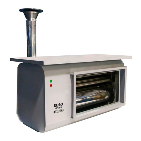
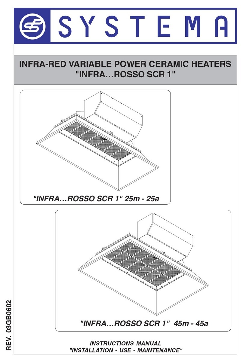
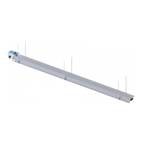
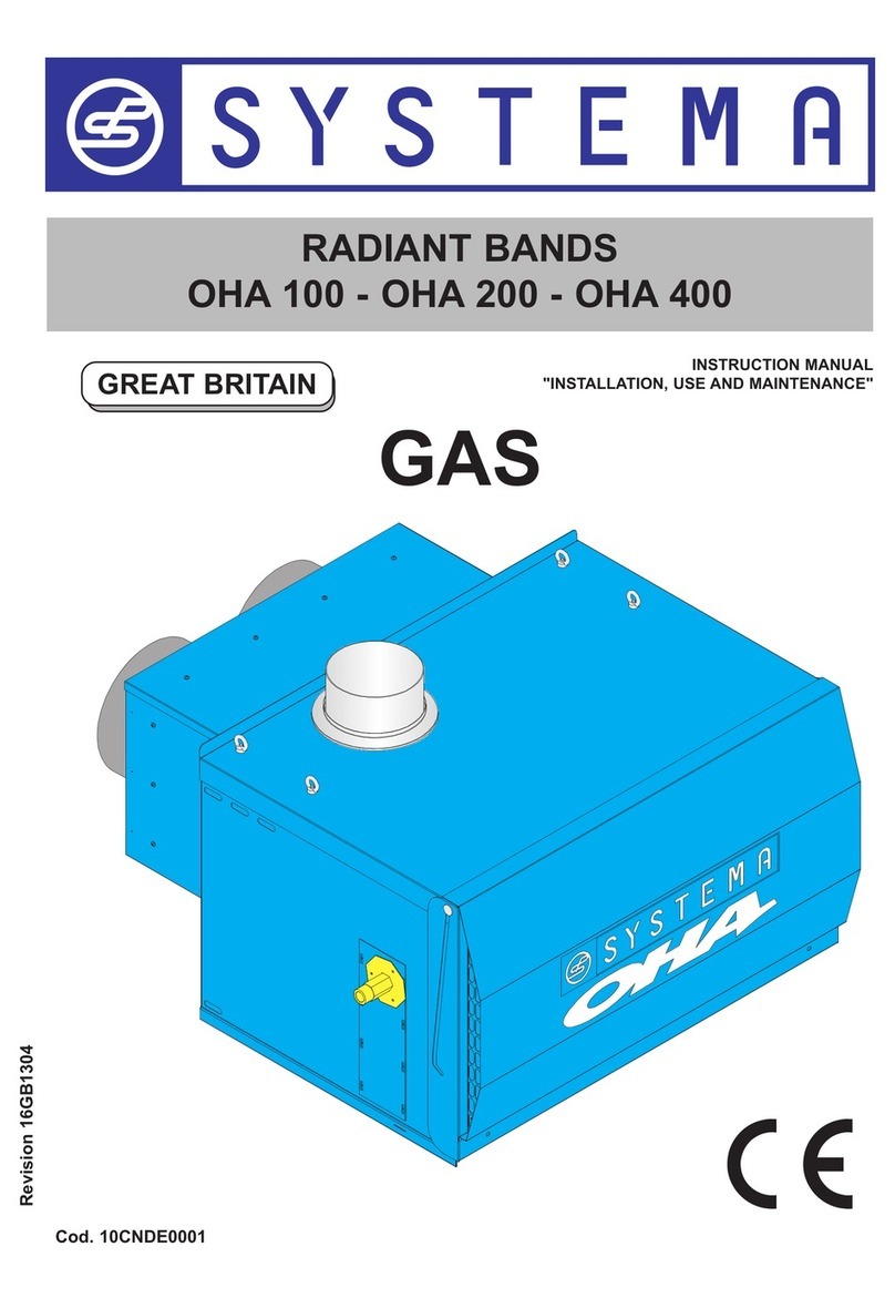
Systema INFRA 6 G User manual

SEALED DIESEL/35 SEC OIL FIRED
RADIANT TUBES
INFRA 6 G - 9 G - 12 G
INSTRUCTION MANUAL
“INSTALLATION, USE AND MAINTENANCE”
GREAT BRITAIN

2
Rev. 03GB0611
SYSTEMA S.p.A. SEALED DIESEL FIRED INFRA RADIANT TUBES
Via San Martino 17/23
S. GIUSTINA IN COLLE (PD)
loc. Fratte Fontane Bianche
PADOVA - ITALY
Tel 0039 0499355663
(8 linee r.a.)
Fax 0039 0499355699
E-mail: [email protected]
technical informations
http://www.systema.it
commercial informations
,,IMPORTANT: Read this manual carefully before starting up the system. In order to improve the product,
Systema reserves the right to modify the content without prior notice.
Appliance
subject to periodic maintenance, depending on the type of fuel, specific applications, room temperature, length
of use etc.

3Rev. 03GB0611
SYSTEMA S.p.A.
SEALED DIESEL FIRED INFRA RADIANT TUBES
1 GENERAL RULES . . . . . . . . . . . . . . . . . . . . . . . . . . . . . . . . . . . . . . . . . . . .5
2 PACKING . . . . . . . . . . . . . . . . . . . . . . . . . . . . . . . . . . . . . . . . . . . . . . . . . . .5
2.1 Packing list . . . . . . . . . . . . . . . . . . . . . . . . . . . . . . . . . . . . . . . . . . . . . . . . . . . . . . . . . . .5
3 GENERAL TECHNICAL CHARACTERISTICS . . . . . . . . . . . . . . . . . . . . . .7
3.1 Description and characteristics of operation . . . . . . . . . . . . . . . . . . . . . . . . . . . . . . .7
3.2 Technical characteristics . . . . . . . . . . . . . . . . . . . . . . . . . . . . . . . . . . . . . . . . . . . . . . .8
3.3 Dimensions . . . . . . . . . . . . . . . . . . . . . . . . . . . . . . . . . . . . . . . . . . . . . . . . . . . . . . . . . . .9
3.4 Tubes composition . . . . . . . . . . . . . . . . . . . . . . . . . . . . . . . . . . . . . . . . . . . . . . . . . . . .10
3.5 Exploded view of INFRA 6G radiant tube . . . . . . . . . . . . . . . . . . . . . . . . . . . . . . . . . .12
3.5.1 Legend INFRA 6G radiant tube . . . . . . . . . . . . . . . . . . . . . . . . . . . . . . . . . . . . . . . . . . . . . . . . . . . . . . . . .13
3.6 Exploded view of INFRA 9G radiant tube . . . . . . . . . . . . . . . . . . . . . . . . . . . . . . . . . .14
3.6.1 Legend INFRA 9G radiant tube . . . . . . . . . . . . . . . . . . . . . . . . . . . . . . . . . . . . . . . . . . . . . . . . . . . . . . . . .15
3.7 Exploded view of INFRA 12G radiant tube . . . . . . . . . . . . . . . . . . . . . . . . . . . . . . . . .16
3.7.1 Legend INFRA 12G radiant tube . . . . . . . . . . . . . . . . . . . . . . . . . . . . . . . . . . . . . . . . . . . . . . . . . . . . . . . .17
3.8 Various types of reflectors and support brackets . . . . . . . . . . . . . . . . . . . . . . . . . . .18
4 INSTALLATION . . . . . . . . . . . . . . . . . . . . . . . . . . . . . . . . . . . . . . . . . . . . . . .19
4.1 Places of installation and safety distances . . . . . . . . . . . . . . . . . . . . . . . . . . . . . . . . .19
4.2 Assembly of the unit . . . . . . . . . . . . . . . . . . . . . . . . . . . . . . . . . . . . . . . . . . . . . . . . . . .20
4.2.1 INFRA 6G assembly . . . . . . . . . . . . . . . . . . . . . . . . . . . . . . . . . . . . . . . . . . . . . . . . . . . . . . . . . . . . . . . . .20
4.2.2 INFRA 9G assembly . . . . . . . . . . . . . . . . . . . . . . . . . . . . . . . . . . . . . . . . . . . . . . . . . . . . . . . . . . . . . . . . .21
4.2.3 INFRA 12G assembly . . . . . . . . . . . . . . . . . . . . . . . . . . . . . . . . . . . . . . . . . . . . . . . . . . . . . . . . . . . . . . . .22
4.2.4 Burner and exhaust fan assembly . . . . . . . . . . . . . . . . . . . . . . . . . . . . . . . . . . . . . . . . . . . . . . . . . . . . . . .23
4.2.5 INFRA assembly . . . . . . . . . . . . . . . . . . . . . . . . . . . . . . . . . . . . . . . . . . . . . . . . . . . . . . . . . . . . . . . . . . . .24
5 FITTING THE APPLIANCE . . . . . . . . . . . . . . . . . . . . . . . . . . . . . . . . . . . . . .28
5.1 Fitting on the ceiling . . . . . . . . . . . . . . . . . . . . . . . . . . . . . . . . . . . . . . . . . . . . . . . . . . .28
6 DISCHARGE DUCTS . . . . . . . . . . . . . . . . . . . . . . . . . . . . . . . . . . . . . . . . . .29
6.1 Discharge ducts on the roof . . . . . . . . . . . . . . . . . . . . . . . . . . . . . . . . . . . . . . . . . . . . .29
6.2 Flue ducts through the wall . . . . . . . . . . . . . . . . . . . . . . . . . . . . . . . . . . . . . . . . . . . . .31
6.3 Maximum lengths . . . . . . . . . . . . . . . . . . . . . . . . . . . . . . . . . . . . . . . . . . . . . . . . . . . . . .32
6.3.1 Roof terminal (type B22) . . . . . . . . . . . . . . . . . . . . . . . . . . . . . . . . . . . . . . . . . . . . . . . . . . . . . . . . . . . . . .33
6.3.2 Wall terminal (type B22) . . . . . . . . . . . . . . . . . . . . . . . . . . . . . . . . . . . . . . . . . . . . . . . . . . . . . . . . . . . . . .34
7 ELECTRICAL INSTALLATION . . . . . . . . . . . . . . . . . . . . . . . . . . . . . . . . . . .35
7.1 Wiring diagram for connection to CE control panel . . . . . . . . . . . . . . . . . . . . . . . . .35
7.2 Electrical connection . . . . . . . . . . . . . . . . . . . . . . . . . . . . . . . . . . . . . . . . . . . . . . . . . . .36
7.3 Functioning and use of INFRA G electric board . . . . . . . . . . . . . . . . . . . . . . . . . . . . .37
7.3.1 FRONT OF THE INSTRUMENT . . . . . . . . . . . . . . . . . . . . . . . . . . . . . . . . . . . . . . . . . . . . . . . . . . . . . . . .37
7.3.2 MODIFICATION OF INSTRUMENT PARAMETERS . . . . . . . . . . . . . . . . . . . . . . . . . . . . . . . . . . . . . . . .37

4
Rev. 03GB0611
SYSTEMA S.p.A. SEALED DIESEL FIRED INFRA RADIANT TUBES
8 BURNER CHARACTERISTICS . . . . . . . . . . . . . . . . . . . . . . . . . . . . . . . . . .38
9 FINAL CHECK AND START UP OF THE INSTALLATION . . . . . . . . . . . . .40
9.1 Preliminary procedure . . . . . . . . . . . . . . . . . . . . . . . . . . . . . . . . . . . . . . . . . . . . . . . . . .40
9.2 Measuring performance . . . . . . . . . . . . . . . . . . . . . . . . . . . . . . . . . . . . . . . . . . . . . . . .41
9.2.1 Measuring the temperature of the combustion air . . . . . . . . . . . . . . . . . . . . . . . . . . . . . . . . . . . . . . . . . . .42
10 GUARANTEE . . . . . . . . . . . . . . . . . . . . . . . . . . . . . . . . . . . . . . . . . . . . . . . .43
10.1 Object and duration of the guarantee . . . . . . . . . . . . . . . . . . . . . . . . . . . . . . . . . . . . .43
10.2 Exclusions from the guarantee . . . . . . . . . . . . . . . . . . . . . . . . . . . . . . . . . . . . . . . . . .43
10.3 Competence . . . . . . . . . . . . . . . . . . . . . . . . . . . . . . . . . . . . . . . . . . . . . . . . . . . . . . . . . .43
10.4 Operativity and effectiveness of the guarantee . . . . . . . . . . . . . . . . . . . . . . . . . . . . .43
10.5 Responsibility . . . . . . . . . . . . . . . . . . . . . . . . . . . . . . . . . . . . . . . . . . . . . . . . . . . . . . . .43
10.6 Legal disputes - Territorial competence and rights of the parties . . . . . . . . . . . . . .43
11 SHUTTING DOWN . . . . . . . . . . . . . . . . . . . . . . . . . . . . . . . . . . . . . . . . . . . .44
12 STANDARDS . . . . . . . . . . . . . . . . . . . . . . . . . . . . . . . . . . . . . . . . . . . . . . . .44
12.1 General standards . . . . . . . . . . . . . . . . . . . . . . . . . . . . . . . . . . . . . . . . . . . . . . . . . . . . .44
12.2 Fire prevention regulations . . . . . . . . . . . . . . . . . . . . . . . . . . . . . . . . . . . . . . . . . . . . .44
13 NOTES . . . . . . . . . . . . . . . . . . . . . . . . . . . . . . . . . . . . . . . . . . . . . . . . . . . . .45

5Rev. 03GB0611
SYSTEMA S.p.A.
SEALED DIESEL FIRED INFRA RADIANT TUBES
1 GENERAL RULES
This instructions booklet is an integral part and essential
of the appliance and must be kept with care near the
appliance for all future consultation.
Read the instructions and warnings in this booklet care-
fully, as they supply important indications for safety,
installation, use and maintenance.
ATTENTION ! !
If you lose this booklet, contact the manufacturer imme-
diately.
The appliance has been built for heating large work
environments such as industrial and handicrafts sheds
in general, warehouses, premises with large-scale air
renewal, loading bays outside sheds, environments for
sports activities (gymnasiums), by means of the princi-
ple of thermal radiation; this allows the heating of single
specific area and, if suitably combined with other
appliances, heating of the whole environment. It may be
used for heating premises for zootechnical uses (poultry
and swine farms) and for agriculture (greenhouses) and
in all those industrial production cycles (ovens) in which
heating is needed without there being any contact bet-
ween the product and the combustion fumes.
It is not allowed to use the appliance to heat premises
intended for handicraft or industrial activities in which
the processes carried out and the materials stored invol-
ve a risk of the formation of gas, vapours or dust which
could cause fire or explosions.
The appliance must be installed by professionally quali-
fied personnel, responsible for compliance with the
safety regulations in force. The manufacturer declines
all responsibility in the event of damage due to incorrect
installation or to improper and/or incorrect use of the
appliance.
The packing material (nylon, polystyrene foam, wood,
staples, etc.) must not be left within the reach of chil-
dren, as they are potential hazards.
The appliance must be started up for the first time by
qualified personnel.
In the event of stopping and/or malfunction of the
appliance, switch it off. Any repairs or replacement of
components must be carried out exclusively by skilled
personnel, using only original spare parts. Failure to
abide by these rules may be detrimental to the safety of
the appliance.
To guarantee good operation of the appliance it is indi-
spensable to follow scrupulously the indications given
by the manufacturer and to have maintenance carried
out on the appliance by skilled personnel (at least once
a year).
2 PACKING
2.1 Packing list
a) The exhaust fan is delivered in a cardboard box.
b) The burner is delivered in a cardboard box with the
Instruction Manual.
c) Brackets, springs to fix the reflectors, a small
bag with the screws to connect brackets and
radiant tubes are delivered in a cardboard box.
d) The radiant pipes required for each INFRA radiant
heater are packed separately, with all the neces-
sary connections and sleeves in a cardboard box.
e) The reflectors are supplied packed one of the top
of the other, to save space.
,,ATTENTION! Remove any protective plastic film
from the hoods before fitting them onto the brac-
kets.

6
Rev. 03GB0611
SYSTEMA S.p.A. SEALED DIESEL FIRED INFRA RADIANT TUBES
Draw 1 Packing the accessory parts of the radiant tube

7Rev. 03GB0611
SYSTEMA S.p.A.
SEALED DIESEL FIRED INFRA RADIANT TUBES
1
1
2
2
3
4
A
B
B
A
E
D
C
Draw 1a Packing of the RBT
hoods
Draw 1b Assembly of the RBT
hoods
1) Bag containing split pins and washer
2) Pads of rock wool (in packs of 20 pieces)
3) Mirror reflecting hoods
4) Top protection hoods
1) Place the pad (D) on top of the reflecting
hood (E).
2) Place the top hood (C) on top of the pad and
the reflecting hood.
3) Secure the parts with the split pins through
the central holes (B).
4) Join the hoods together, securing one to
another by inserting the clip in the outside
holes (A).
3 GENERAL TECHNICAL CHARACTERISTICS
3.1 Description and characteri-
stics of operation
The "INFRA" sealed diesel fired radiant combustion
tube is made of aluminized tube, in a U shape, combu-
stion takes place inside the tube through a mixture of
vaporized fuel and air, bringing the outside surface to an
average temperature of about 350°C. The steady ope-
ration temperature is reached in a few minutes. The
control, mixing, combustion and ignition are enclosed in
a container, installed in the head of each module.
Above the whole length (6, 9, 12 m) of the radiating tube
there is a mirror surface, with the purpose of reflecting
down the heat radiation produced by the tube itself. This
surface may also be provided with rock wool insulation
on the top part (the so-called RBT version). The control
of the conditions of comfort inside the environment is
assigned to the infrared-sensitive thermostats located in
the immediate vicinity of the work area and placed on an
electric panel which can switch on and off one or more
modules at the same time. This offers the possibility of
heating either the whole environment or individual
areas, even at different temperatures.

8
Rev. 03GB0611
SYSTEMA S.p.A. SEALED DIESEL FIRED INFRA RADIANT TUBES
SEALED DIESEL FIRED INFRA RADIANT TUBES TECHNICAL CHARACTERISTICS
TECHNICAL CHARACTERISTICS
SERIES INFRA G
BURNER TYPE LO35 G
MODELS INFRA 6G INFRA 9G INFRA 12G
Nominal thermal flow
MAX kW 29,27 32,11 32,11
MIN kW 26,19 26,19 26,19
Nominal thermal power
MAX kW 26,09 29,55 29,55
MIN kW 23,35 24,10 24,10
Burner pressure Diesel fuel
MAX Bar 10 12 12
MIN Bar 888
Nozzle diameter Diesel fuel
MAX G.P.H.
0.65/45°
MIN G.P.H
Actual combustion perfor-
mance
VBS needle 33,5 5,5
VRT needle 33,5 5,5
Nominal consumption Diesel
fuel
MAX Kg/h 2,47 2,71 2,71
MIN Kg/h 2,21 2,21 2,21
Complete appliance weight Kg 103,5 148,5 148,5
Electrical supply V/Hz 230/50 230/50 230/50
Max. Electric power consumption kW 0,575 0,575 0,575
Protection degree
From the side IP44
From the top IP42
Diesel fuel connection IN-OUT A-R 1/4G" 1/4G" 1/4G"
Air connection diameter (M) * mm 80
Exhaust connection diameter (M) * mm 100
Maximum temperature radiant pipe °C 400
Type B22
3.2 Technical characteristics
* Use flexible and rigid ducts toDIN standards or the standards in force in the country were the installation is carried
out
Tab. 1

9Rev. 03GB0611
SYSTEMA S.p.A.
SEALED DIESEL FIRED INFRA RADIANT TUBES
9444
23902878 2970 511
6494
2900 5762304
5970
603
525
8940
57929972902 2900
12398
2340
11910
250
600
680
Ø 46.5
Ø 46.5
Ø 100
425
3.3 Dimensions
INFRA 12 G - 5 SUPPORT BRACKETS
INFRA 9 G - 4 SUPPORT BRACKETS
INFRA 6 G - 3 SUPPORT BRACKETS
Draw 2 Dimensions of INFRA
radiant tubes
Draw 3

10
Rev. 03GB0611
SYSTEMA S.p.A. SEALED DIESEL FIRED INFRA RADIANT TUBES
Draw 4 Tubes composition
3.4 Tubes composition
INFRA 12 G
ADHESIVE TYPE A
ADHESIVE TYPE B
INFRA 9 G
INFRA 6 G

11 Rev. 03GB0611
SYSTEMA S.p.A.
SEALED DIESEL FIRED INFRA RADIANT TUBES
Pos. Code Description Material Model
101CNRA5999 BURNER CONNECTION F/F STAINLESS STEEL
INFRA 6G
INFRA 9G
INFRA12G
201CBTU0614 EXCHANGER TUBE Ø108x2 mm. LENGTH 2770 mm. STAINLESS STEEL INFRA 9G
INFRA 12G
303CLMA0801 CAST IRON Ø 108 mm. COUPLING COLLAR FOR
TUBES CONNECTION CAST IRON INFRA 9G
INFRA 12G
401CBTU0616 EXCHANGER TUBE Ø108x2 mm. LENGTH 5800 mm. ALUMINIZED STEEL INFRA 9G
INFRA 12G
501CLCU0002 ALUM. CONNECTING BEND Ø108-80 mm. ALUMINIUM
INFRA 6G
INFRA 9G
INFRA12G
601CBTU0617 EXCHANGER TUBE Ø80x1,5 mm. LENGTH 5800 mm. ALUMINIZED STEEL INFRA 9G
INFRA12G
703CLCU0001 CAST IRON Ø 80 mm. COUPLING COLLAR FOR TUBES
CONNECTION CAST IRON INFRA 9G
INFRA12G
801CBTU0618 EXCHANGER TUBE Ø80x1,5 mm. LENGTH 5785 mm. ALUMINIZED STEEL INFRA 6G
901CLRA6003 EXHAUST FAN CONNECTOR Ø 80 mm. ALUMINIUM
INFRA 6G
INFRA 9G
INFRA12G
10 01CBTU0614 EXCHANGER TUBE Ø108x2 mm. LENGTH 2770 mm. STAINLESS STEEL INFRA 9G
INFRA12G
11 01CBTU0619 EXCHANGER TUBE Ø80x1,5 mm. LENGTH 2885 mm. ALUMINIZED STEEL INFRA 9G
13 01CBTU0620 EXCHANGER TUBE Ø108x2 mm. LENGTH 2870 mm. STAINLESS STEEL INFRA 6G
15 01CBTU0621 EXCHANGER TUBE Ø80x2 mm. LENGTH 5650 mm. ALUMINIZED STEEL INFRA 6G
16 01CBTU0615 EXCHANGER TUBE Ø108x2 mm. LENGTH 2900 mm. ALUMINIZED STEEL INFRA12G
17 01CBTU0622 EXCHANGER TUBE Ø108x2 mm. LENGTH 2665 mm. ALUMINIZED STEEL INFRA 6G
Tab. 2

12
Rev. 03GB0611
SYSTEMA S.p.A. SEALED DIESEL FIRED INFRA RADIANT TUBES
21 3
321
20
12
3.5 Exploded view of INFRA 6G
radiant tube
Draw 5 Exploded view of INFRA 6G radiant tube

13 Rev. 03GB0611
SYSTEMA S.p.A.
SEALED DIESEL FIRED INFRA RADIANT TUBES
13
3.5.1 Legend INFRA 6G radiant tube
Tab. 3
Pos. Code Description
103CNBR0062 LO35 G IDEA Diesel fuel burner
200CNTU0617 Re circulation pipe
300CNVI1050 M8 zinc plated nut
401CLRA6003 Ø 80 mm. exhaust fan connection
501CIST0733 First support bracket (upper part)
601CBTU0621 Split pin
701CNCO0132 Stainless steel reflectors
801CNCI0070 Spring with eyelet for reflector fixing
901CNMO0285 Support bracket (upper part)
10 01CVGR2652 Aluminium connecting bend Ø 108 - 80 mm.
11 01CLCU0002 HH M8x16 mm zinc plated screw
12 00CNVI1050 Support bracket (lower part)
13 01CVGR2653 First support bracket (lower part)
14 01CBTU0620 Burner connector
15 01CIST0733 Exhaust fan
16 01CNRA5999 Collecting tray for maintenance purposes.
17 03CEAS0022 Aluminized steel Ø 80x2 mm exchanger tube (delivery side) length 2665 mm.
18 01CVVA0761 Aluminized steel Ø 108x2 mm exchanger tube (return side) length 5650 mm.
19 01CBTU0622 Stainless steel Ø 80x1,5 mm exchanger tube (delivery side) length 2870 mm.
20 00CNVI1002 HH M8x40 mm zinc plated screw
21 00CNRO0368 8x17 mm zinc plated washer

14
Rev. 03GB0611
SYSTEMA S.p.A. SEALED DIESEL FIRED INFRA RADIANT TUBES
14
3
5
6
7
8
9
10
11
12
13
1
22
19
18
21
2
20
3.6 Exploded view of INFRA 9G
radiant tube
Draw 6 Exploded view of INFRA 9G radiant tube

15 Rev. 03GB0611
SYSTEMA S.p.A.
SEALED DIESEL FIRED INFRA RADIANT TUBES
3.6.1 Legend INFRA 9G radiant tube
Tab. 4
Pos. Code Description
103CNBR0062 LO35 G IDEA Diesel fuel burner
200CNTU0617 Re circulation pipe
300CNVI1050 M8 zinc plated nut
401CNRA5999 Burner connector
501CIST0733 First support bracket (upper part)
601CBTU0614 Split pin
701CNCO0132 Stainless steel reflectors
801CNCI0070 Spring with eyelet for reflector fixing
901CNMO0285 Cast iron sleeve Ø 108 mm for tubes connection
10 03CLMA0801 Support bracket (upper part)
11 01CBTU0616 Aluminium connecting bend Ø 108 – 80 mm.
12 01CVGR2652 HH M8x16 mm zinc plated screw
13 01CLCU6002 Support bracket (lower part)
14 00CNVI1050 Cast iron sleeve Ø 80 for tubes connection
15 01CVGR2653 First support bracket (lower part)
16 03CLCU0001 Exhaust fan Ø 80 mm. connection
17 01CIST0733 Exhaust fan
18 01CLRA6003 Collecting tray for maintenance purposes
19 03CEAS0022 Aluminized steel Ø 80x1,5 mm. exchanger tube(return side) length 2885 mm.
20 01CBTU0617 Aluminized steel Ø 108x2 mm. exchanger tube(delivery side) length 5800 mm.
21 01CBTU0619 Stainless steel Ø 108x2 mm. exchanger tube(delivery side) length 2770 mm.
22 01CVVA0761 Aluminized steel Ø 80x1,5 mm. exchanger tube(return side) length 5800 mm.
23 00CNVI1002 HH M8x40 mm zinc plated screw
24 00CNRO0368 8x17 mm zinc plated washer

16
Rev. 03GB0611
SYSTEMA S.p.A. SEALED DIESEL FIRED INFRA RADIANT TUBES
14
3
1
23
19
18
2
25 3
325
24
3.7 Exploded view of INFRA 12G
radiant tube
Draw 7 Exploded view of INFRA 12G radiant tube

17 Rev. 03GB0611
SYSTEMA S.p.A.
SEALED DIESEL FIRED INFRA RADIANT TUBES
3.7.1 Legend INFRA 12G radiant tube
Tab. 5
Posizione Codice Descrizione
103CNBR0062 LO35 G IDEA Diesel fuel burner
200CNTU0617 Re circulation pipe
300CNVI1050 M8 zinc plated nut
401CNRA5999 Burner connector
501CIST0733 First support bracket (upper part)
601CBTU0614 Stainless steel Ø 108x2 mm. exchanger tube (delivery side) length 2770 mm.
701CNCO0132 Split pin
801CNCI0070 Stainless steel reflectors
901CNMO0285 Spring with eyelet for reflector fixing
10 03CLMA0801 Cast iron sleeve Ø 108 mm for tubes connection
11 01CBTU0616 Aluminized steel Ø 108x2 mm. exchanger tube (delivery side) length 5800 mm.
12 01CVGR2652 Support bracket (upper part)
13 01CLCU6002 Aluminium connecting bend Ø 108 - 80 mm. HH
14 00CNVI1050 M8x16 zinc plated screw
15 01CVGR2653 Support bracket (lower part)
16 03CLCU0001 Cast iron sleeve Ø 80 mm for tubes connection
17 01CIST0733 First support bracket (lower part)
18 01CLRA6003 Exhaust fan Ø 80 mm. connection
19 03CEAS0022 Exhaust fan
20 01CBTU0617 Aluminized steel Ø 80x1,5 mm. exchanger tube (return side) length 5800 mm.
21 01CBTU0618 Aluminized steel Ø 80x1,5 mm. exchanger tube (return side) length 5785 mm.
22 01CBTU0615 Aluminized steel Ø 108x2 mm. exchanger tube (return side) length 2900 mm.
23 01CVVA0761 Collecting tray for maintenance purposes
24 00CNVI1002 HH M8x40 mm zinc plated screw
25 00CNRO0368 8x17 mm zinc plated washer

18
Rev. 03GB0611
SYSTEMA S.p.A. SEALED DIESEL FIRED INFRA RADIANT TUBES
3.8 Various types of reflectors
and support brackets
Draw 8 Final support bracket (the middle brackets without the upper side; Draw 5; 6; 7)
Draw 9 Hood anchoring bracket
Draw 10 Hood anchoring bracket Draw 11 Hood anchoring bracket
Upper side

19 Rev. 03GB0611
SYSTEMA S.p.A.
SEALED DIESEL FIRED INFRA RADIANT TUBES
12
34
5
6
7
Draw 12 Hood anchoring bracket
4.1 Places of installation and
safety distances
Draw 13
Example of
protection
of the
motor of a
bridge
crane
Combustible materials in store must be at a sufficient
distance for the radiating pipe to prevent them from rea-
ching dangerous temperatures. Laboratory experiments
have shown that combustible materials (with a surface
of 0.5 m2), placed at a distance of 1.5 metres from the
module and parallel to it, never reach temperatures that
4 INSTALLATION
could be considered dangerous. In particular cases, if it
is impossible to respect these distances (for example
motors of the carriages on a bridge crane, electric
cables, lamps, cabins) suitable steps must be taken to
screen heat-susceptible materials from the module heat
radiation (see Draw 16).
MINIMUM DISTANCES OF COMBUSTIBLE
MATERIALS FROM THE HEAT RADIATING TUBE
(wood, cardboard, plastic materials, pallets, etc.)
ACCORDING TO:
- STANDARD DIN 3372 part 6, par. 3.12
- DVGW, G63/11, part 12/3.1.2
In any case the distance must be such that the maxi-
mum surface temperature of the materials does not
exceed 85°C.
The bearing elements must not be heated on large
surfaces to over 50°C.
1) Reflecting parabola
2) Heat radiating tube
3) Insulation (rock wool 3 cm thick)
4) Protecyive plate (stainless steel, galvanised plate,
aluminium)
5) Plate support must allow air passage for ventilating
the motor
6) Eletric motor
7) Bridge crane

20
Rev. 03GB0611
SYSTEMA S.p.A. SEALED DIESEL FIRED INFRA RADIANT TUBES
4.2 Assembly of the unit
To assembly the various components of INFRA radiant
tubes, follow the instructions provided below
4.2.1 INFRA 6G assembly
Begin assembly of the tube, starting with the bend:
1) Fit the two tubes (delivery and return) into the bend
for about 120 mm (Draw 14), hammering slightly if
necessary, taking care to place a piece of wood
between the hammer and the sleeve (see Draw
15). Then fix them in place, using the screws sup-
plied with the bend
2) Assemble the connecting collar Ø 108 mm and the
other delivery tube (Draw 14), fixing them with the
screws supplied, taking care to push the tubes half
way into the collar (about 150 mm), hammering
slightly if necessary, taking care to place a piece of
wood between the hammer and the sleeve (see
Draw 15).
,,ATTENTION: Fit the tube taking care that the
end with adhesive tape is positioned at the
opposite extremity to the sleeve.To correctly
assemble the tube refer to the exploded view
(Draw 4) and to the table 2.
Draw 14
Draw 15
Ø 108 mm. SLEEVE
RETURN TUBE
Wood
DELIVERY TUBES
This manual suits for next models
2
Table of contents
Other Systema Heater manuals