Systema INFRA 6 ES Series Quick start guide

01IT1810
ENGLISH
Installation, use and maintenance
instruction manual
Cod. 10CNDE0063
Rev. 02GBEN13112018
INFRA ES
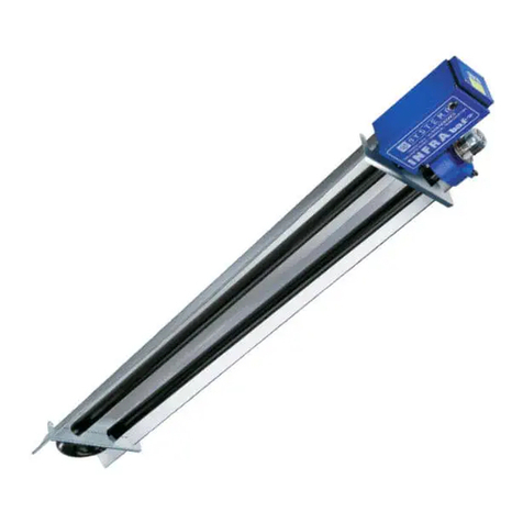
GAS-TIGHT MODULES WITH RADIANT TUBES
Standard models: INFRA 6 ES 28, INFRA 6 ES 35,
INFRA 9 ES 45, INFRA 9 ES 53,
INFRA 12 ES 45, INFRA 12 ES 60,
INFRA 15 ES 60
Recirculation models: INFRA 9 ES-R 45, INFRA 12 ES-R 45
Bluline Models: INFRA 6 ES 35 BL, INFRA 9 ES 53 BL,
INFRA 12 ES 60 BL
02GBEN13112018

2
SYSTEMA S.p.A. INFRA ES rev. 02GBEN13112018
Symbols used in the manual
N.B.
IMPORTANT
READ CAREFULLY BEFORE USE.
KEEP FOR FUTURE REFERENCE
Before installation, check that the local conditions of distribution, the nature of the gas and
of the pressure are compatible with the setting of the appliance.
In order to improve the product, Systema reserves the right to modify its contents
as required and without warning.
Via Antonio Ceccon, 3
35010 LOREGGIA (PD) ITALIA
Tel. 0039 049.935.5663
(8 linee r.a.)
Fax 0039 049.935.5699
E-mail: [email protected]
Technical information
Sales information
ISO 9001: 2015
DANGER
WARNING
ATTENTION
-
-
-
-

3
I
SYSTEMA S.p.A. INFRA ES rev. 02GBEN13112018
SUMMARY
SUMMARY
1 GENERAL RULES ............................................................................................................................................5
1.1 TERMINOLOGY USED IN THE MANUAL..................................................................................................................6
2 PACKAGING ..................................................................................................................................................... 7
2.1 PACKING LIST ...........................................................................................................................................................7
3 CARATTERISTICHE ......................................................................................................................................... 8
3.1 SPECIFICATIONS ......................................................................................................................................................9
3.1.1 Mandatory information according to Regulation (EU) 2015/1188 - Directive2009/125/EC DIRECTIVE ................10
3.2 MAIN COMPONENTS OF THE APPLIANCE .............................................................................................................13
3.3 IDENTIFICATION PLATE AND INFORMATION LABELS...........................................................................................14
3.3.1 Labels placed on the channel tubes.......................................................................................................................15
3.4 DIMENSIONS OF BURNER AND EXTRACTOR .......................................................................................................15
3.5 COMPONENTS INFRA 6 ES (ALL THE MODELS)....................................................................................................17
3.6 COMPONENTS INFRA 9 ES 45.................................................................................................................................18
3.7 COMPONENTS INFRA 9 ES 53 (STANDARD E BLULINE) ......................................................................................19
3.8 COMPONENTS INFRA 9 ES-R 45.............................................................................................................................20
3.9 COMPONENTS INFRA 12 ES 45...............................................................................................................................22
3.10 COMPONENTS INFRA 12 ES 60 (STANDARD E BLULINE) ....................................................................................23
3.11 COMPONENTS INFRA 12 ES-R 45...........................................................................................................................24
3.12 COMPONENTS INFRA 15 ES 60...............................................................................................................................25
3.13 COMPONENTS BRUCIATORE..................................................................................................................................27
3.14 POSITION OF IGNITION AND DETECTION ELECTRODE......................................................................................28
3.15 NOZZLE POSITION....................................................................................................................................................28
3.16 TYPES OF REFLECTIVE HOODS AND SUPPORT BRACKETS..............................................................................28
4 INSTALLATION AND ASSEMBLY.........................................................................................................................29
4.1 PRELIMINARY OFFLOADING OPERATIONS ...........................................................................................................29
4.2 DISTANCE FROM COMBUSTIBLE MATERIALS AND OTHER EQUIPMENT ..........................................................29
4.3 APPLIANCE INSTALLATION AND ASSEMBLY .........................................................................................................30
4.4 EXHAUST AND INTAKE PIPES .................................................................................................................................37
4.4.1 Roof coaxial exhaust and intake pipes...................................................................................................................37
4.4.2 Roof coaxial exhaust and intake pipes...................................................................................................................38
4.4.3 Wall exhaustpipes ..................................................................................................................................................39
4.4.4 Maximum lengths of the exhaust and intake pipes ................................................................................................40
4.4.5 Components of exhaust and intakepipes ...............................................................................................................41
4.4.5.1 Separate ceiling fume exhaust and air intake (type C32)........................................................................................................ 41
4.4.5.2 Separate wall fume exhaust and air intake (type C12)............................................................................................................ 42
4.4.5.3 Wall fumes exhaust (type B22)................................................................................................................................................ 42
4.4.5.4 Ceiling fumes exhaust (type B22)............................................................................................................................................ 43
4.4.5.5 Coaxial ceiling fume exhaust and air intake (type C32)........................................................................................................... 44
4.4.5.6 Coaxial wall fume exhaust and air intake (type C32)............................................................................................................... 45
5 GAS PIPING........................................................................................................................................................46
5.1 CONNECTING THE EQUIPMENT .............................................................................................................................46
6 ELECTRICAL SYSTEM........................................................................................................................................ 48
6.1 INTERNAL EQUIPMENT CONNECTION DIAGRAM.................................................................................................48
6.2 STANDARD VERSION APPLICATION INTERNAL WIRING......................................................................................49
6.3 DIAGRAM OF CONNECTION TO THE CONTROLPANELS .....................................................................................50
6.3.1 Power supply cable entry .......................................................................................................................................50
6.4 ELECTRICAL CONNECTION OF AN APPLIANCE TO A CE/A SERIESPANEL ........................................................51
6.4.1 CE/A-type electrical panel for 1 Infra module, detail of connections ......................................................................52
6.4.2 CE/A-type electrical panel for 2 Infra modules, detail of connections ....................................................................53
6.4.3 CE/A-type electrical panel for 4 Infra modules, detail of connections ....................................................................54
6.5 SLIM ELECTRIC PANEL FOR 3 INFRA MODULES, DETAIL OF CONNECTIONS...................................................55

4
I
SYSTEMA S.p.A. INFRA ES rev. 02GBEN13112018
SUMMARY
6.6 ELECTRICAL CONNECTION OF AN APPLIANCE WITH AN INET SERIES PANEL (OPTIONAL)...........................56
6.6.1 Connection diagram of combustion unit and INET network controller panel with 2 to 16 units..............................58
6.6.2 Conguration of INFRA network interface card on board for operation with multiple combustion units and INET
network controller panel .........................................................................................................................................59
6.6.3 INFRA ES connection with INET card ....................................................................................................................60
7 SYSTEM FINAL TESTING AND START-UP.....................................................................................................61
7.1 PRELIMINARY CHECKS BEFORE IGNITION...........................................................................................................61
7.2 FIRST IGNITION......................................................................................................................................................... 61
7.2.1 Checking of gas pressure at the burner inlet..........................................................................................................61
7.2.2 Checking gas pressure at the gas valve outlet.......................................................................................................61
7.3 ADJUSTING THE RECIRCULATING DAMPER (ES-R MODELS ONLY) ..................................................................63
7.4 OUTPUT MEASUREMENT ........................................................................................................................................64
7.4.1 Measurement of the combustion air temperature...................................................................................................64
7.5 POSSIBLE AIR DAMPER ADJUSTMENT..................................................................................................................65
7.5.1 Air damper adjustment ...........................................................................................................................................66
8 MAINTENANCE...................................................................................................................................................67
8.1 FUEL CHANGE ..........................................................................................................................................................67
8.2 FAULT RESOLUTION.................................................................................................................................................68
9 WARRANTY ........................................................................................................................................................ 69
9.1 OBJECT AND DURATION OF THE WARRANTY ......................................................................................................69
9.2 EXCLUSIONS FROM THE WARRANTY....................................................................................................................69
9.3 COMPETENCES ........................................................................................................................................................69
9.4 OPERATION AND EFFICIENCY OF THE WARRANTY.............................................................................................70
9.5 RESPONSIBILITY ......................................................................................................................................................70
9.6 JUDICIAL DISPUTES - TERRITORIAL COMPETENCE AND POWERS OF THE PARTIES ....................................70
10 STORAGE AND DISPOSAL .................................................................................................................................71
10.1 STORAGE ..................................................................................................................................................................71
10.2 DISPOSAL..................................................................................................................................................................71

5
1
SYSTEMA S.p.A. INFRA ES rev. 02GBEN13112018
GENERAL RULES
1 GENERAL RULES
■
■
■
■
for further consultation.
■-
tant information regarding safety, installation, use and maintenance.
■In case of loss of this manual, contact the manufacturer immediately.
■
■
■
■
installation.
■
■
■-
keted.
■
■
DANGER
■To ensure correct operation of the appliance it is essential to strictly follow the instructions given by the manu-
facturer, to use original accessories and spare parts and to arrange maintenance to be performed by qualied
personnel (at least once a year).
■Do not install the system at premises intended for craft or industrial activities where the processing items
and any materials in storage pose the risk of formation of gases, vapours or dusts that could generate res or
explosions.
■-
tions in force.
■
■
■
■-
■
-

6
1
SYSTEMA S.p.A. INFRA ES rev. 02GBEN13112018
GENERAL RULES
■
-
-
■
■
■
■
■
■
-
-
-
■
■
■
■
■
■
■
■-
■-
-
■
■
-
"System under maintenance, IT IS FORBIDDEN to carry out
operations on the control panel of the equipment.”
■
-
■
1.1 TERMINOLOGY USED IN THE MANUAL
Radiant pipe device
-
tion duct.
GCV
-
-
in the fuel.

7
2
SYSTEMA S.p.A. INFRA ES rev. 02GBEN13112018
PACKAGING
2 PACKAGING
2.1 PACKING LIST
a.
c.
d.
e.
f.
ATTENTION
Perform the unpacking operation with the aid of appropriate equipment and/or protections.
-
NCV
Heat output
Professionally qualied personnel
-
Risk
Danger
Potential source of damage.
Damage
User
An individual or organisation that uses the devices.

8
3
SYSTEMA S.p.A. INFRA ES rev. 02GBEN13112018
SPECIFICATIONS
3 SPECIFICATIONS
-
-
tion, ignition and air intake systems are enclosed in a sealed container, installed at the head of the delivery
-
-
Fig. 3.1 RBT hoods packaging
Fig. 3.2 RBT hoods assembly
hoods
through the central holes (B)
the external holes (A).
1
1 2
2
3
4
C
D
E
A
A
B
B

9
3
SYSTEMA S.p.A. INFRA ES rev. 02GBEN13112018
SPECIFICATIONS
3.1 TECHNICAL DATA
Tab. 3.1 Technical data
Standard INFRA ES MODEL INFRA 6
ES 28
INFRA 6
ES 35
INFRA 9
ES 45
INFRA 9
ES 53
INFRA 9
ES-R 45
INFRA
12 ES
45
INFRA
12 ES
60
INFRA
12 ES-R
45
INFRA
15 ES
60
Bluline INFRA ES MODEL --
INFRA
6 ES 35
BL
--
INFRA
9 ES 53
BL
-- --
INFRA
12 ES 60
BL
-- --
Type of equipment B22 - C12 - C32 - C42
Heat output (NCV) kW 28,0 35,0 45,0 53,0 45,0 45,0 60,0 45,0 60,0
Combustion yield (NCV) % 90,5 90,9 90,8 90,6 93,3 90,1 90,7 93,4 90,7
Electrical power supply 1/N/PE ~ 50Hz 230V
Air pressure switch calibra-
tion Pa 60 60 60 60 60 60 60 60 60
Extractor power W 100 100 100 180 180 100 180 180 180
Extractor fan Ø mm 133 133 145 170 170 145 170 170 170
Gas attachment (female) inches 1/2 1/2 1/2 1/2 1/2 1/2 1/2 1/2 1/2
Air connection (male) Ø mm 100 100 100 100 100 100 100 100 100
Fume attachment (female) Ø mm 100 100 100 100 100 100 100 100 100
Weight standard version kg 82,5 82,5 139 140,5 141,5 176 177,5 178,5 209,5
Weight with RBT hood insu-
lated on top kg 101,5 101,5 167,5 169 170 214 215,5 216,5 247,5
Nominal consumption at 15°C and 1013.25 mbar
Natural gas G20 m3/h 2,96 3,70 4,76 5,61 4,76 4,76 6,35 4,76 6,35
Butane G30 kg/h 2,21 2,76 3,55 4,18 3,55 3,55 4,73 3,55 4,73
Propane G31 kg/h 2,18 2,72 3,50 4,12 3,50 3,50 4,66 3,50 4,66

10
3
SYSTEMA S.p.A. INFRA ES rev. 02GBEN13112018
SPECIFICATIONS
Model identication INFRA 6 ES 28 INFRA 6 ES 35
INFRA 6 ES 35 BL INFRA 9 ES 45
Tipo di riscaldamento: With radiant pipes With radiant pipes With radiant pipes
Combustibile (gassoso) Natural gas (G20) Natural gas (G20) Natural gas (G20)
Data Symbol Unit Value Value Value
Emissions due to ambient heating - nitrogen oxides
(≤200mg/kWhinput)NOX
[mg/kWhinput]
(GCV) 156 145 164
Thermal power
Nominal thermal power Pnom kW 25,3 31,8 40,9
Minimum thermal power Pmin kW N.A. N.A. N.A.
Minimum thermal output (percentage of nominal thermal output) .. % N.A. N.A. N.A.
Nominal thermal output of the radiant tube system (if applicable) Psystem kW N.A. N.A. N.A.
Nominal thermal output of the radiant tube segment (if appli-
cable) Pheater,i kW N.A. N.A. N.A.
Number of identical radiant tube segments n - - - -
Irradiation factor (standard hoods)
irradiation factor at the nominal thermal output RFnom % 60,3 65,7 55,5
irradiation factor at the minimum thermal output RFmin % N.A. N.A. N.A.
Irradiation factor (isolated RBT hoods, excluding BLULINE models)
irradiation factor at the nominal thermal output RFnom %
irradiation factor at the minimum thermal output RFmin % N.A. N.A. N.A.
Electrical auxiliary consumption
At nominal thermal power elmax kW 0,110 0,110 0,117
At minimum thermal power elmin kW N.A. N.A. N.A.
In stand-by mode elSB kW 0,000 0,000 0,000
Power required for permanent pilot ame
requiredpowerforthepilotame(ifapplicable) Ppilot kW N.A. N.A. N.A.
Useful efciency (GCV)
Usefulefciencyatnominalheatoutput ηth,nom % 81,5 81,9 81,8
Usefulefciencyatminimumheatoutput ηth,min % N.A. N.A. N.A.
Usefulefciencyoftheradianttubesegmentattheminimum
thermal power (if applicable) ηi% N.A. N.A. N.A.
Envelope losses
Envelope insulation class U W/m2K N.A. N.A. N.A.
Envelope loss factor Fenv % - - -
Heat generator to be installed out of the heated zone no no no
Thermal power control type One phase One phase One phase
Seasonal energy efciency of ambient heating (≥74%) with
standard hood ηS% 78,7 82,1 76,8
Seasonalenergyefciencyofambientheating(≥74%)withiso-
lated RBT hood, excluding BLULINE models ηS%
Tab. 3.2 Regulatory Data (EU) 2015/1188 (1 of 3)
3.1.1 Mandatory information according to Regulation (EU) 2015/1188 - Directive2009/125/EC
DIRECTIVE

11
3
SYSTEMA S.p.A. INFRA ES rev. 02GBEN13112018
SPECIFICATIONS
Tab. 3.3 Regulatory Data (EU) 2015/1188 (2 of 3)
Model identication INFRA 9 ES 53
INFRA 9 ES 53 BL INFRA 9 ES-R 45 INFRA 12 ES 45
Heating type: With radiant pipes With radiant pipes With radiant pipes
Fuel (gaseous) Natural gas (G20) Natural gas (G20) Natural gas (G20)
Data Symbol Unit Value Value Value
Emissionsduetoambientheating-nitrogenoxides(≤200mg/
kWhinput)NOX
[mg/kWhinput]
(GCV) 159 75 149
Thermal power
Nominal thermal power Pnom kW 48,0 42,0 40,5
Minimum thermal power Pmin kW N.A. N.A. N.A.
Minimum thermal output (percentage of nominal thermal output) .. % N.A. N.A. N.A.
Nominal thermal output of the radiant tube system (if applicable) Psystem kW N.A. N.A. N.A.
Nominal thermal output of the radiant tube segment (if appli-
cable) Pheater,i kW N.A. N.A. N.A.
Number of identical radiant tube segments n - - - -
Irradiation factor (standard hoods)
irradiation factor at the nominal thermal output RFnom % 66,5 55,5 62,4
irradiation factor at the minimum thermal output RFmin % N.A. N.A. N.A.
Irradiation factor (isolated RBT hoods, excluding BLULINE models)
irradiation factor at the nominal thermal output RFnom %
irradiation factor at the minimum thermal output RFmin % N.A. N.A. N.A.
Electrical auxiliary consumption
At nominal thermal power elmax kW 0,168 0,168 0,117
At minimum thermal power elmin kW N.A. N.A. N.A.
In stand-by mode elSB kW 0,000 0,000 0,000
Power required for permanent pilot ame
requiredpowerforthepilotame(ifapplicable) Ppilot kW N.A. N.A. N.A.
Useful efciency (GCV)
Usefulefciencyatnominalheatoutput ηth,nom % 81,6 84,0 81,1
Usefulefciencyatminimumheatoutput ηth,min % N.A. N.A. N.A.
Usefulefciency oftheradiant tubesegmentat theminimum
thermal power (if applicable) ηi% N.A. N.A. N.A.
Envelope losses
Envelope insulation class U W/m2K N.A. N.A. N.A.
Envelope loss factor Fenv % - - -
Heat generator to be installed out of the heated zone no no no
Thermal power control type One phase One phase One phase
Seasonal energy efciency of ambient heating (≥74%) with
standard hood ηS% 82,1 78,8 79,7
Seasonalenergyefciencyofambientheating(≥74%)withiso-
lated RBT hood, excluding BLULINE models ηS%

12
3
SYSTEMA S.p.A. INFRA ES rev. 02GBEN13112018
SPECIFICATIONS
Tab. 3.4 Regulatory Data (EU) 2015/1188 (3 of 3)
Model identication
INFRA 12 ES 60
INFRA 12 ES 60
BL
INFRA 12 ES-R 45 INFRA 15 ES 60
Heating type: With radiant pipes With radiant pipes With radiant pipes
Fuel (gaseous) Natural gas (G20) Natural gas (G20) Natural gas (G20)
Data Symbol Unit Value Value Value
Emissions due to ambient heating - nitrogen oxides
(≤200mg/kWhinput)NOX
[mg/kWhinput]
(GCV) 136 75 154
Thermal power
Nominal thermal power Pnom kW 54,4 42,0 54,4
Minimum thermal power Pmin kW N.A. N.A. N.A.
Minimum thermal output (percentage of nominal thermal output) .. % N.A. N.A. N.A.
Nominal thermal output of the radiant tube system (if applicable) Psystem kW N.A. N.A. N.A.
Nominal thermal output of the radiant tube segment (if appli-
cable) Pheater,i kW N.A. N.A. N.A.
Number of identical radiant tube segments n - - - -
Irradiation factor (standard hoods)
irradiation factor at the nominal thermal output RFnom % 67,7 62,4 66,5
irradiation factor at the minimum thermal output RFmin % N.A. N.A. N.A.
Irradiation factor (isolated RBT hoods, excluding BLULINE models)
irradiation factor at the nominal thermal output RFnom %
irradiation factor at the minimum thermal output RFmin % N.A. N.A. N.A.
Electrical auxiliary consumption
At nominal thermal power elmax kW 0,168 0,168 0,168
At minimum thermal power elmin kW N.A. N.A. N.A.
In stand-by mode elSB kW 0,000 0,000 0,000
Power required for permanent pilot ame
requiredpowerforthepilotame(ifapplicable) Ppilot kW N.A. N.A. N.A.
Useful efciency (GCV)
Usefulefciencyatnominalheatoutput ηth,nom % 81,7 84,1 81,7
Usefulefciencyatminimumheatoutput ηth,min % N.A. N.A. N.A.
Usefulefciency ofthe radianttube segmentat theminimum
thermal power (if applicable) ηi% N.A. N.A. N.A.
Envelope losses
Envelope insulation class U W/m2K N.A. N.A. N.A.
Envelope loss factor Fenv % - - -
Heat generator to be installed out of the heated zone no no no
Thermal power control type One phase One phase One phase
Seasonal energy efciency of ambient heating (≥74%) with
standard hood ηS% 82,9 82,6 82,3
Seasonalenergyefciencyofambientheating(≥74%)withiso-
lated RBT hood, excluding BLULINE models ηS%

13
3
SYSTEMA S.p.A. INFRA ES rev. 02GBEN13112018
SPECIFICATIONS
Tab. 3.5 Main components
3.2 MAIN COMPONENTS OF THE APPLIANCE
Description Code
INFRA 6 ES 28
INFRA 6 ES 35
INFRA 6 ES 35 BL
INFRA 9 ES 45
INFRA 9 ES 53
INFRA 9 ES 53 BL
INFRA 9 ES-R 45
INFRA 12 ES 45
INFRA 12 ES 60
INFRA 12 ES 60 BL
INFRA 12 ES-R 45
INFRA 15 ES 60
Solenoid valve 00CLEV0537 XXXXXXXXX
Monophase motor 100 W with fan Ø 133 01CEMO0302 X X
Monophase motor 100 W with fan Ø 145 01CEMO0303 X X
Monophase motor 180 W with fan Ø 170 01CEMO0307 X X X X X
Pressure switch-reset point 60 Pa (opening) 00CEPR1105 XXXXXXXXX
Control equipment 00CEAP0779 XXXXXXXXX
X
GAS VALVE TECHNICAL SPECIFICATIONS
Code................................................................................... 00CLEV0537
......................................................................
................................................... IP 54
Closure time ....................................................................... <1s
...............................................................
....................................................
...................................................................... 4.8 m3
ELECTRICAL MOTOR PLATE DATA - single phase asynchronous
Code.....................................00CEMT0287 ....................... 04CEMO2601
......................................
........... ............
..........................................................
.............0.72 A ................................... 1.36 A
Condenser............................ ...........................
Insulation ..............................H........................................... B
PRESSURE SWITCH SPECIFICATIONS
Code.....................................00CEPR1105
..................
..............5000 Pa
.............
...........Ø 6.2 mm
..........

14
3
XXXXXXXX XX/XXXX
XXXXXXXXXXX XXXXXXXXXXX
XXXXXXXXXXXXXXXX
XX XXX XXX,XXX,XXX,XXX
XX XXX XXX XXX XXX XXX
XXX
XXX
XXX
XXX
XXX
XXX
XXX
XXX
XXX
XXX
XXX
XXX
XXX
XXX
XXX
XXX
XXX
XXX
XXX
XXX
XXX
XXX
XXX
XXX
XXX
XXX
XXX
XXX
XXX
X/XX XXX/XX
X XXX
SYSTEMA S.p.A. INFRA ES rev. 02GBEN13112018
SPECIFICATIONS
CONTROL EQUIPMENT TECHNICAL SPECIFICATIONS
Code................................................................................... 00CEAP0779
Mod..................................................................................... DFCE32
......................................................................
.......................................................
................................................................. 20 s
Safety start time.................................................................. max 10 s
.......................................................... < 1s
.......................................................................... Electric
3.3 IDENTIFICATION PLATE AND INFORMATION LABELS
Fig. 3.3 Position of identication plate and
warning labels
Important
the serial number of the product is essential
for adequate and fast service.
Important
READ THE INSTALLATION INSTRUCTIONS CAREFULLY
BEFORE INSTALLING
THE APPLIANCE. READ THE INSTRUCTIONS FOR USE
BEFORE TURNING ON. FOR TYPE '' B '' APPLICATIONS,
PREPARE SUITABLY VENTILATED PREMISES.
SYSTEMA S.p.A.
Via S. Martino 17/23
Santa Giustina in Colle (PD) - ITALY
Serial number Year XXXX
Model Destination
CategoryPIN Code
Heat output (Hi) Type
Heating capacity (Hi)
Supply pressure
Max burner pressure
Nozzle diameter
Electrical Power Supply Degree of protection
Electrical PowerNOx
Class
Regulated for XXXXXXXXXXXX
Max nominal consumption
Types of gas

15
3
SYSTEMA S.p.A. INFRA ES rev. 02GBEN13112018
SPECIFICATIONS
3.4 DIMENSIONS OF BURNER AND EXTRACTOR
3.3.1 Labels placed on the channel tubes
Fig. 3.5 Dimensions of burner/extractor (models ES 6; ES 9)
Fig. 3.4 Labels positioned on the ends of the tubes
INFRA 6 ES 28
INFRA 6 ES 35
INFRA 6 ES 35 BL
INFRA 9 ES 45
INFRA 9 ES 53
INFRA 9 ES 53 BL
INFRA 9 ES-R 45
(red)

16
3
SYSTEMA S.p.A. INFRA ES rev. 02GBEN13112018
SPECIFICATIONS
Fig. 3.6 Dimensions of burner/extractor (models ES 12; ES 15)
INFRA 12 ES 45
INFRA 15 ES 60
INFRA 12 ES 60
INFRA 12 ES 60 BL
INFRA 12 ES-R 45

17
3
SYSTEMA S.p.A. INFRA ES rev. 02GBEN13112018
SPECIFICATIONS
3.5 COMPONENTS INFRA 6 ES (ALL THE MODELS)
POS. CODICE DESCRIPTION INFRA 6
ES 28
INFRA 6
ES 35
INFRA 6
ES 35 BL
101FITT0609 Burner 28 kW 1 - -
01FITT0610 Burner 35 kW - 1 1
2 00CNVI1006 Hex head screw M8X50 mm galvanised 2 2
3 00CNDA0148 Nut M8 galvanised 4 4 4
4 01CBTU0631 Aluminium steel exchanger tube Ø102X1.5mm, length
5800 mm 1 1 1
5 01CNCO0132 Split pin 2 2 2
601CNCI0071 Stainlesssteelreectinghood 2 2 -
01CNCA0078 Aluminisedsteelreectinghood - - 2
7 01CNMO0286 Spring with eyelets, length 500 mm 3 3 3
8 01CLCU0153 Elbow Ø102 180° moulded 1 1 1
9 01CNST3009 Support bracket 3 3 3
10 01CBTU0632 Aluminium steel exchanger tube Ø102X1.5mm, length
5800 mm with 2 spiral turbulators 1 1 1
11 00CNDA0156 Galvanised nut M6 with washer 2 2 2
12 01CLCA3008 Bracket locking hook bolt 1 1 1
13 01CNRA6018 Extractor coupling 1 1 1
14 01CNGU3123 Gasket 1 1 1
15 03FITT0029 Complete fume extractor 100 W with fan Ø 133 1 1 1
Fig. 3.7
Tab. 3.6
(red)

18
3
SYSTEMA S.p.A. INFRA ES rev. 02GBEN13112018
SPECIFICATIONS
3.6 COMPONENTS INFRA 9 ES 45
Fig. 3.8
(red)

19
3
SYSTEMA S.p.A. INFRA ES rev. 02GBEN13112018
SPECIFICATIONS
3.7 COMPONENTS INFRA 9 ES 53 (STANDARD AND BLULINE)
Fig. 3.9
(red)

20
3
SYSTEMA S.p.A. INFRA ES rev. 02GBEN13112018
SPECIFICATIONS
3.8 COMPONENTS INFRA 9 ES-R 45
Fig. 3.10
See also
(red)
This manual suits for next models
10
Table of contents
Other Systema Heater manuals
Popular Heater manuals by other brands

TREVIDEA
TREVIDEA G3ferrari TEPOR G60004 user manual

Hoberg
Hoberg SEH01-2000R instructions

Pinnacle Products International
Pinnacle Products International HeatStream HS- 45-KFA User manual – operating guide

for Living
for Living 043-7362-4 Installation and user manual

L.B. White
L.B. White GreenGro Plus HD220 Owner's manual and instructions

Bimar
Bimar SP815 Instruction booklet