Taarup BIO+ B4000 User manual

Operator’s manual
Bale processor
Model Taarup BIO+ B4000
with options
16655216_EN
Operator`s manual BIO+ processor B4000 English,
issue 07-06, document version 6, programme version 1.04

2
Operator´s manual BIO bale processor B4000

3
CE certificate of conformity
We,
Kverneland Group
Gottmadingen GmbH & Co.KG
Hauptstrasse 99
D-78244 Gottmadingen
Germany
declare under our sole responsibility that the product:
Bale processor type Taarup B4000
to which this declaration relates corresponds to the relevant basic safety
and health requirements of Directive 98/37/EU.
Gottmadingen, July 2006
Enter here the serial number of your
machine:
CE certificate of conformity
Kverneland Group manufacturers of farm machinery reserve the right to
change designs and/or specifications without notice. This does not include
an obligation to make changes to machines previously supplied.
Casper Böhme
General Manager

4
Operator´s manual BIO bale processor B4000
Guarantee
Taarup products are guaranteed for a period of one year from the date of delivery, against defects in
material and workmanship.
Components not manufactured by Kverneland, i.e. electrics and hydraulics, PTO shafts and tyres are
guaranteed according to the original manufacturer’s recommendation.
The components listed below have limited guarantee due to their function:
Tyres
Pre-stretcher rollers
Belts
Knives
Lamps
Fuses
Oil filter
Hydraulic seals of motors, valves and cylinders.
Weakening due to wear and tear is considered to be normal for these parts. The product guarantees for
these components are limited to manufacturing defects, breakage, poor workmanship, transport damage
etc on new machines.
Any damage to bearings that are fitted with grease nipples is not covered under the standard product
guarantee, if the damage is shown to be caused by rust or due to the ingress of liquids. Such damage is
caused by insufficient lubrication or the use of low quality lubricants.
Any damage caused by the use of corrosive additives in or nearby the machine is also not covered.
If a failure is expected to be covered under the guarantee, the owner or its representative should inform
the dealer when parts and/or repair work is required. Any guaranty claim should be applied for within the
period of guarantee.
The dealer should fill in one guarantee claim form for each matter and forward it to the Kverneland sales
company or importer before the 10th of the following month after the claim was raised.
The damaged parts should be marked with the number of the corresponding warranty claim and should
be stored for 6 months by the dealer, available for inspection by the Kverneland sales company or
importer if required.
Due to the operation of the Taarup products being out of the manufacturer’s control, the guarantee
covers the product quality only. Performance or any consequential losses are not covered.
The guarantee may be invalid if:
a) spurious spare parts are used or the product is repaired or modified without the Kverneland authorisa-
tion.
b) operator’s and service instructions given by the manufacturer are not complied with.
c) The machine is used for other purposes than those designed for.
The guarantee does not cover damage caused by normal wear.
Public safety regulations require from the manufacturer of this machine that all safety aspects regarding
the use of the machine is thoroughly evaluated. As a result of these obligations Kverneland and its
importer or sales company are not responsible for the function of components not shown in the spare
parts catalogue covering this product.
Kverneland reserve the right to change the product with no obligation to previously supplied machines.
Guarantee

5
Content
Content
CE certificate of conformity ................................ 3
Guarantee .......................................................... 4
Introduction ........................................................ 6
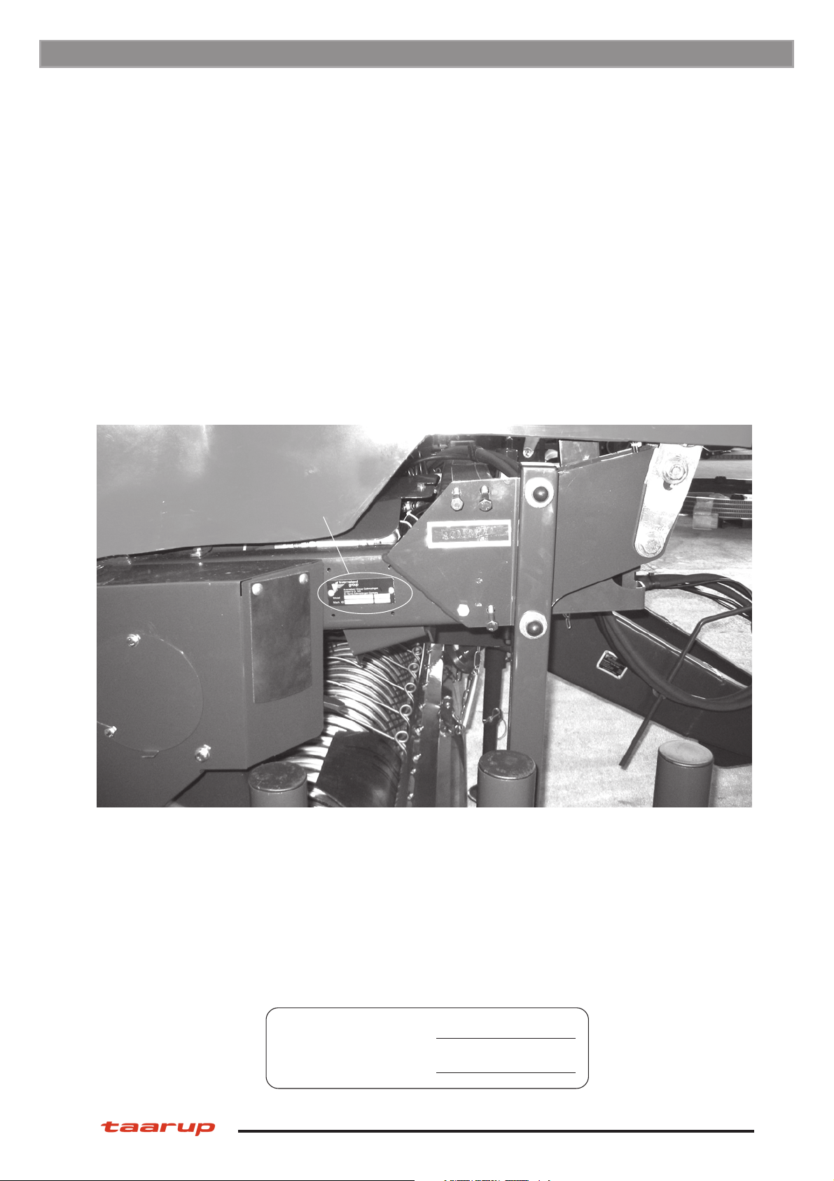
Machine identification ......................................... 7
Technical specifications ..................................... 8
Dimensions ........................................................ 9
Model descriptions ........................................... 10
Summary of operator’s instructions .................. 11
Safety ............................................................... 14
1 Preparing a new machine ...................... 21
1.1 Packing .................................................. 21
1.2 Final assembly ....................................... 21
1.3 Hydraulics .............................................. 21
1.4 Electronics ............................................. 21
2 Tractor requirements .............................. 21
3 Stretch film ............................................. 21
4 Operating the machine ........................... 22
4.1 Connecting machine .............................. 22
4.2 Use clean hydraulic oil! .......................... 25
4.3 Set-up of pick-up .................................... 26
4.4 Crop cutting system ............................... 27
4.5 Net binding ............................................. 31
4.7 Shear bolts on roller drive ...................... 33
4.8 Prestretcher positioning ......................... 33
4.9 Film cutter .............................................. 33
4.10 Processing bales .................................... 35
4.11 Parking ................................................... 44
4.12 Out of season storage ............................ 44
5 The computerised control system .......... 45
5.0 Mode of operation - sensors and valves 45
5.1 The command panel .............................. 45
5.2 Symbols ................................................. 46
5.3 Display information regarding
panel connection .................................... 50
5.4 Idle mode ............................................... 50
5.5 User functions screen displays .............. 51
5.6 Process mode screen displays .............. 54
5.7 Dealer functions ..................................... 58
5.8 Service functions .................................... 61
6 Maintenance .......................................... 63
6.1 Maintenance of mechanic
components ........................................... 63
6.2 Maintenance hydraulics ......................... 66
6.3 Maintenance electrics & electronics ....... 66
7 Troubleshooting ..................................... 67
7.1 Troubleshooting hydraulics .................... 68
7.2 Troubleshooting electrics ....................... 69
Notes ............................................................... 71

6
Operator´s manual BIO bale processor B4000
The future of farming™
Introduction
We congratulate you on the purchase of your new Taarup product. You
have chosen a product which will give you satisfaction through a network
of efficient dealers where function, finish, after sales service and spare
parts are always at hand.
All Taarup products are designed and tested in close co-operation with
farmers and contractors to ensure optimal function and reliability.
Please read this manual before using your new machine.
We wish you all the best with your Taarup product.
Yours faithfully
Kverneland Group
Introduction
Kverneland Gottmadingen GmbH & Co.KG
Haupstrasse 99
D-78244 Gottmadingen
Germany

7
Machine identification
The machine’s serial number and the manufacturer’s address are found on the number plate of
the machine. See illustration below.
The serial number and year of manufacture for this machine is given below. This number is im-
portant with regard to service and the correct supply of spare parts.
This marking, together with the enclosed CE certificate of conformity, means that the machine
complies with all substantial health and safety requirements and is in accordance with directive
98/37/EU.
Serial number :
Year of manufacture :
Serial number
Machine identification

8
Operator´s manual BIO bale processor B4000
Technical specifications
Valid for standard equipped machine with wheel size 500/50-17"
Description Data
Dimensions
Total length ........................................................................... 4500 mm
Width .................................................................................... 2800 mm
Height ................................................................................... 2300 mm
Weight ......................................................................................... 3250 kg
Wheel dimension
Regular................................................................................. 500/50-17"
Optional ................................................................................ 500/45-22.5"
Optional ................................................................................ 600/40-22.5"
Tractor requirements
Hydraulic hitch/tractor drawbar ............................................ Ø52/Ø
Oil flow required (free return) ............................................... 35 l/min
Oil pressure for ring speed 50 rpm....................................... min. 190 bar
PTO connection ................................................................... 6 splines/540 rpm
Electric power supply ........................................................... 12V
Pick-up
Working width ....................................................................... 2100 mm
Number of tine rows ............................................................. 5
Support wheels .................................................................... adjustable 12 positions
Cutter unit
Number of knives ................................................................. 14
Knife distance ....................................................................... 70 mm
Foreign body protection ....................................................... Spring on every blade
Bale chamber
Diameter............................................................................... 1250 mm
Width .................................................................................... 1220 mm
Number of rollers.................................................................. 18
Roller diameter ..................................................................... 190 mm
Low friction plates ................................................................ Option
Chamber lock ....................................................................... Hooks
Chain lubrication .................................................................. Automatic
Roller bearing lubrication, standard ..................................... 5 nipple banks
Roller bearing lubrication, optional ....................................... 6 nipple banks
Binding ........................................................................................ Net
Prestretcher
Film width ............................................................................. 750mm
Nominal pre-stretch .............................................................. approx. 70%
Max. pre-stretcher ring speed .............................................. approx. 50 revs/min
No. of film layers .................................................................. 2+2+...
Operating system ........................................................................ Programmable controls
Technical specifications

9
2300
4500
2800
Dimensions
Valid for machine with wheel size 500/50-17"
All measures are in mm (1" = 25.4mm)
Dimensions

10
Operator´s manual BIO bale processor B4000
Model descriptions
Regular specifications
Fixed chamber bale processor provided with hydraulic operated pick-up. Mechanic drive of pick-
up, cutting unit and roller chamber during baling. Hydraulic drive of baling chamber and pre-
stretcher ring during stretch film wrapping. Computerised control of all hydraulic functions via
solenoid valve bank. Lighting equipment.
Options
Road lights
Low friction lining of roller chamber side panels
Drop mat
Bale turner
Extra set of knives
Knife grinding kit
Hydraulic rotor engagement
Film break sensor
½ speed of bale rotation
Kit for wrapping in sloping terrain
Ask your Dealer for further optional equipment.
Model descriptions

11
Summary of operator’s instructions
a) Connect bale processor’s drawbar to trac-
tor’s drawbar. Lift and secure the parking leg.
b) Connect hydraulic hoses to the single act-
ing outlet with free return to tank, or to a dou-
ble acting outlet.
The pump capacity should be set to maxi-
mum 35 litres/min at an engine speed offer-
ing PTO speed of 540 revs/min.
When connected to tractor featuring con-
stant-pressure hydraulics (like John Deere
30-, 40- and 50-series), the centre line of the
spool valve should be closed.
c) The electric/electronic controls require a
steady 12V power supply. The battery cable
included with the bale processor offers a
steady supply when connected to the battery
terminals. The brown wire shall be connected
to the battery’s positive terminal, the blue
wire to the battery’s negative terminal. The
power supply should under no circumstances
come from the lighter socket!
d) Connect machine to tractor’s PTO shaft
using 540 rpm gear.
e) Connect command panel and power sup-
ply.
f) Check the oil flow from the tractor at a PTO
speed of 540 revs/min. At correct flow pre-
stretcher speed on a new machine should be
max. 50 revs/min and max. 50-53 revs/min on
a machine being used for some time (corre-
sponding to oil flow of 35 litres/min). Too high
ring speed may cause inaccuratepositioning
of ring when approaching film cutting posi-
tion. Too large oil flow may cause harmful oil
heating.
g) Select desired mode (Manual or Auto).
h) Start baling. When chamber has reached
90% filling, a short alarm sounds. When
chamber has reached 100% filling, a continu-
ous alarm sounds. Stop baling to proceed
with net and film wrapping (automatic or man-
ual, depending on the selected operation
mode).
i) If bale processor is operated in Manual
mode, confirm by OK the required sequences
to proceed.
j) When the bale is completely wrapped and
unloaded continue baling.
k) The reacting speed of the cylinders can be
adjusted by means of the set screws of the
lever housings of the valve bank.
Remember that the operator is obliged to ensure that the product is
baled & wrapped properly.
Summary of operator’s instructions
This summary is intended to give a survey only. Before operation
you must make yourself familiar with the safety advice and detailed
descriptions as contained in the complete Operator’s Manual.

12
Operator´s manual BIO bale processor B4000
Safety
Before operating, adjusting or servicing the
machine it is important that the safety in-
structions in this manual are carefully read
and understood by those, which are directly
concerned. (Fig. 1)
Whilst all care and attention has been taken
in the design and production of this machine,
as with all machinery there remains a certain
amount of risk to personnel whilst the machi-
ne is in use. It is strongly recommended that
users and operators take all possible precau-
tions to ensure both their own safety and that
of the others that may be in the vicinity.
Read and observe the safety instructions in
this manual. Safety is your responsibility!
Pay particular attention to this symbol.
It means that there could be a serious ha-
zard. It emphasises precautions, which have
to be complied with in order to prevent acci-
dents.
This symbol can be found throughout this
manual and on the warning signs of the
machine. They are for your safety and should
be observed at all time.
Be careful when other people or animals
are close by!
Never start the machine when people or
animals are close by tractor or machine.
Never stand between the tractor wheels and
machine. (Fig. 2)
Bear in mind regulations regarding the lower
age of operators of this kind of machines.
Use of the machine
The machine should be used only for the
purpose it has been designed for.
Use personal protection devices
Do not wear loose clothing, which might
catch in any of the moving parts. In dusty
conditions an approved mask must be used.
(Fig. 3)
Take care of excessive noise level. Some
tractor/implement combinations, depending
on conditions, may cause noise level beyond
85dB at the operator’s ears, even in a “Q”
cab. In these conditions ear defenders must
be worn. Keep cab windows and doors clos-
ed to reduce noise level.
The machine must be connected to a
correctly sized tractor
The weight of the tractor must correspond to
the maximum weight of the machine when
operated. Follow domestic law and regula-
tions. (Fig. 4)
Make sure that the tractor has the correct
PTO gear engaged. A machine designed for
an input speed of 540 rpm. should never be
connected to a tractor with 1000 rpm. output
speed engaged. The normal PTO speed is
given on a label close to the PTO input shaft.
Connecting machine to tractor
must always be carried out as described in
this manual. If connection should be carried
out with drawbar, one of the parts (tractor or
machine’s drawbar) must have a clevis. The
drawbar pin must be secured with a lock pin.
(Fig. 5)
Observe national regulations regarding road
transport. Some countries require the use of
safety chain when a trailed machine is towed
along public roads.
Think of safety while operating the machi-
ne
Stop the tractor engine and remove the
ignition key prior to carrying out repairs,
cleaning, lubrication or maintaining the mac-
hine. (Fig. 6)
Safety guards
Make sure all guards are in good order and
fitted correctly. Do not attempt to start the
machine before ensuring this. (Fig. 7)
Pay particular attention to the plastic guards
of the PTO shaft. If damaged they must be
replaced. The chain locks of the guards must
always be fitted on a suitable place on the
tractor and the machine to prevent the outer
plastic guards turning.
Hydraulics
Be very careful when dealing with hydraulics.
Use eye protection and gloves. Escaping
hydraulic oil under pressure might penetrate
into the skin and cause serious infection. See
a doctor if you have been exposed to injury.
(Fig. 8)
Take care that nobody is close to the machi-
ne when the hydraulic functions are being
operated.
Safety

13
Fig. 2Fig. 1
Fig. 3 Fig. 4
Fig. 6Fig. 5
Fig. 7 Fig. 8
Safety

14
Operator´s manual BIO bale processor B4000
When uncoupling machine and when
leaving tractor/machine
When uncoupling, all hydraulic functions
must be in neutral position. The machine
must be lowered to the ground and be safely
secured. If the machine has parking chocks
they should be used at the wheels. Never
allow children to play or stay near agricultural
machinery. (Fig. 9)
Drive safely
Beware of your responsibility, - carelessness
or negligence may cause serious injury or
even death. (Fig. 10)
Prior to transporting the machine along public
roads, check wheel bolts and couplings.
Disconnect or lock the hydraulic system.
Drive carefully. Reduce speed when turning
and driving on uneven ground. Take care that
trailed machine does not start swinging or
become unstable.
Please be aware of the danger of overturning
when working on slopes and in soft ground.
Reduce load.
Lights
The owner and operator is responsible of
providing correct lamps and reflectors on the
machine when transported on public roads.
Comply with public regulations. (Fig. 11)
Safety equipment
Always carry first aid equipment on the trac-
tor. Also observe the regulations concerning
fire extinguisher. When working with burning
materials like hay and straw a fire extinguis-
her must be available at all times. (Fig. 12)
Spare parts
For safety reasons use only original spare
parts. The use of spurious spare parts will
cause the Taarup product guarantee to be
invalid. (Fig. 13)
Maintenance
Take care that the machine is properly
maintained and kept in good safe working
condition. Never change the basic technical
construction of the machine.
Safety

15
Fig. 10Fig. 9
Fig. 11 Fig. 12
Fig. 13
Safety

16
Operator´s manual BIO bale processor B4000
Supplementary safety instructions for the
BIO bale processor
This machine is designed for the purpose
of baling & stretch film wrapping of grass or
other straw material in the form of round
bales.
The machine is equipped with warn-
ing signs. If any of the decals are damaged,
they must be replaced. Ordering numbers
are shown on the illustrations in this para-
graph.
Warning sign UH220532. Be careful!
Read and understand the instructions in the
manual before the machine is put into serv-
ice and before attempting adjustment/main-
tenance.
Warning sign UH220534. Disconnect all
electronics before welding commences.
Warning sign UH220548. Disconnect
machine from tractor hydraulics ahead of
any service on machine.
Warning sign UH220900. Stay away from
the danger area while machine is working.
Warning sign UH220524. Danger of
squeezing. Keep distance to machine when
bale is tipped off.
Warning sign UH220538. Keep distance to
the moving cutter arm. Hand or foot can be
trapped and cut.
Warning sign UH220543. Squeeze risk.
Keep away from rotating rollers.
Warning sign UH220903. Keep away from
the pick-up zone when PTO shaft is rotating.
Warning sign UH220902. Keep away from
the raised chamber top section if unless it is
secured.
Warning sign UH220901. Before performing
any work under the chamber top section or in
the bale chamber, the hydraulic shut-off valve
should be closed (valve is positioned at the
front of the machine close to the hydraulic
filter.
Warning sign UH220528. Danger of squeez-
ing. Keep distance to rotating prestretcher
ring.
Warning sign UH220530. Noise level near
the pre-stretcher may exceed 90 dB. Ear
defenders must be worn in this area.
Lifting machine with crane
Safety
Only use approved lifting device. The weight
of the machine is given in paragraph “Techni-
cal specifications”.
Be careful! Make sure that nobody stands
under or near the machine when it is being
lifted.
Fit the lifting straps supplied to the respective
supports (see Assembly Instructions). Use
only a crane-type lifting gear to prevent
supports from deforming.
Attach the lifting straps by the "sling here"
signs. A new machine includes a lifting sprea-
der on top of the machine.
Check that the locking hooks of the baling
chamber are engaged before lifting.
Make sure that straps are securely fastened
before lifting. Use a guide wire to keep ma-
chine in position.

17
UH220534
UH220524
UH220543
UH220538
UH220548
UH220532
UH220528
UH220530
UH220900
UH220901
UH220902UH220903
Safety

18
Operator´s manual BIO bale processor B4000
New machine - be careful
Read the operator’s manual. Great care must
be taken when starting a brand new machine
for the first time. Incorrect assembly, faulty
operations etc. may cause expensive repairs
and loss of profit. The Taarups product guar-
antee does not cover damage occurring
when the instructions given in this book are
not followed.
Pay particular attention to this symbol, -
it emphasises operations where great care
must be taken in order to avoid incorrect as-
sembly, faulty operations etc.
Carefully do as described below when start-
ing a new machine.
Check that the machine is mounted correctly
and that it is not damaged. Assure that elec-
tric wirings have length and position that al-
low machine to move without causing any
damage to the wirings.
Check the connections between tractor and
machine.
Lubricate the machine according to lubrica-
tion chart.
Check wheel bolts torque setting - to be
210Nm (155lb ft).
Cleaning
General
We recommend the use of pressured air
when cleaning the machine. Thus there is
less risk of damaging the bearings of the
machine. If high pressure water is used, keep
clear of bearings and electric components.
Pre-stretch rollers
It is important to keep the pre-stretcher’s roll-
er free from particles, dust, straw and tack.
Use gasoline or similar. Dirty rollers may
cause incorrect stretch of the film and incor-
rect coverage of the bale.
Cylinders
Assure that piston rods are kept free from
aggressive chemicals in order to avoid corro-
sion.
Remember that the operator is obliged to ensure that the product is
baled & wrapped properly.
Safety

19
1 Preparing a new machine
1.1 Packing
Remove all kind of packing. Any equipment
stored in the machine should be removed.
Remove the lifting spreader from the top of
the machine prior to any kind of operation of
the top section of the baler chamber.
1.2 Final assembly
Note! Make sure that the machine is
stable during assembly.
1) Check wheel bolts, tension torque 210Nm
(155 lb.ft).
2) Check that any options are correctly fitted.
1.3 Hydraulics
The hydraulics is ready for use.
The working speed of the hydraulic circuits
can be adjusted by means of the set screws
of the lever housings of the valve bank. See
chapter 4.1.3.
1.4 Electronics
Connect system to tractor’s power supply.
Observe! Assure that power supply has
sufficient capacity with stable connections.
Any risk of short breaks in power supply will
cause system to failure. The battery cable
included with the bale processor offers a
steady supply when connected to the battery
terminals. The brown wire shall be connected
to the battery’s positive terminal, the blue
wire to the battery’s negative terminal. The
power supply should under no circumstances
come from the lighter socket!
Fit control panel in tractor cab.
Connect panel to machine’s driver module.
Switch on the screen. The current time is dis-
played.
2 Tractor require-
ments
The machine is connected to the tractor’s
drawbar/hitch.
One single-acting hydraulic outlet with free
return to tank is required. A double-acting
outlet with max 10 bar back pressure can al-
so be used.
The pump capacity required is 35 litres/min at
a pressure of 190bar with engine speed cor-
responding to PTO speed of 540 rpm.
The electronic controls require a steady 12V
power supply. Use the power supply cable
included with the machine connected to the
battery. The solenoids can be operated at
11V power (measured at the solenoid), while
the electronics require min. 11V input power
(measured at the driver module (black box).
Road lights require a standard 7 pin light
plug.
3 Stretch film
Film width: 750mm only
Tackiness: Good, on inner side only
Strength: High flexibility for proper
enclosure at corners and
edges
Film thickness: Must be at least 25 mi-
crometers due to less
thickness when stretched
Max. roller diameter:
235 mm
Preparing a new machine

20
Operator´s manual BIO bale processor B4000
Caution:
Adjusting, maintenance and repair
work is only to be carried out when
the motor is switched off and the
machine is at a standstill. Remove
ignition key.
4.1.1 Connecting to tractor
4.1.1.1 Connecting & adapting the
drawbar
Connect drawbar to tractor’s drawbar/hitch.
Use the drawbar eye bushing when connect-
ing to tractor drawbar. Fit with ring and circlip
on the upper side in order to avoid damage to
bushing.
The drawbar is to be adjusted in such a way
that the bale processor frame is slanting ap-
prox. 5° to the rear when hooked up. The
posts of the film roll magazines should be
vertical when machine is correct adjusted
standing on horizontal surface.
The drawbar height is set by loosening the
fastening bolt and adjusting the toothed
disks.
Bring the bale processor into correct posi-
tion using the support leg - adjustable
crank. Locate towards the protective cov-
er.
Loosen the right and left drawbar fastening
bolts (on the device) and tilt the drawbar to
hitch height (centre of the ring-hitch fas-
tening bolt to centre of drawbar coupling/
upper edge of pending attachment)
The ring hitch is to be brought into hori-
zontal position by loosening the ring-hitch
fastening bolt.
Ensure that the three fastening bolts are
tight = 1000 Nm
Caution:
When adjusting the drawbar, prevent
the bale processor from rolling away
by placing parking blocks at the heels.
4 Operating the machine
4.1 Connecting machine
A single wide-angle joint universal drive shaft
with integrated ratchet clutch is supplied with
the bale processor. If the bale processor is
overloaded, it switches the driving torque to
zero causing machine to stop. Coupling re-
engages automatically when PTO speed
drops below 200 rpm.
Torque of 1900 Nm ± 10% (for a PTO speed
of 540 rpm) are preset by the universal drive
shaft manufacturer.
Interference of any kind to the coupling
mechanism shall nullify all guarantees for
damage caused by such interference.
The safety guard at the gearbox input shaft
includes mounting openings so that the safe-
ty clutch end of the universal drive shaft can
be pushed onto the central-gear drive shaft
and clamped. The torque moment of the bolts
is 85 Nm. Both mounting openings are then
to be properly closed with the covers.
Operating the machine
4.1.1.2 Adapting & connecting PTO shaft
Table of contents
Other Taarup Farm Equipment manuals
Popular Farm Equipment manuals by other brands

sitrex
sitrex HM 360 Assembly, use and maintenance

MacDon
MacDon CA20 Service manual

Pottinger Landsberg
Pottinger Landsberg Eurotop 421A Operator's manual

Hupfer
Hupfer CTW/O operating instructions

AGROWPLOW
AGROWPLOW AP05 Series owner's manual

Rain-Flo Irrigation
Rain-Flo Irrigation CHALLENGER 1800 Assembly instructions

GrainPro
GrainPro TRANSAFELINER BULK instruction manual

Bush Hog
Bush Hog HDSS Series parts manual

360 YIELD CENTER
360 YIELD CENTER 360 Series installation instructions

Rauch
Rauch MDS 8.2 Operator's manual

Dhollandia
Dhollandia DH-RPL 22 installation manual

Trejon
Trejon Multiforest MF650 Instruction Manual and Maintenance Directions