Tabi Aura User manual

installation instructions
tabi aura
Doc # 100121 | Rev A
Page 1 of 8

Page 2 of 8 | Doc # 100121 | Rev A
safety requirements
Tabi aura - Wall Mounted Frameless Dry Erase
Board, Non-Seismic Applications
The building’s Engineer of Record must be
consulted to determine if there are any seismic
requirements.
Minimum Required Wall Construction
Drywall with metal studs:
• Must be at least 25 ga. (0.018” thick) 33 ksi steel studs
(1.5” x 3.5”)
• Studs on maximum 24” centers
• Must be at least 5/8” thick Type X gypsum drywall
• #6 x 1-1/4” drywall screws on 12” centers
Verify Wall Construction
• CAUTION! Adequate wall construction is required
to support the weight of the board. Minimum wall
construction must be capable of supporting weight
amounts listed in Table 1.
Drywall with wood studs:
• Stud grade SPF, DF-L or Hem-Fir (1.5” x 3.5”)
• Studs on 24” centers
• Must be at least 5/8” thick Type X gypsum drywall
• #6 x 1-1/4” drywall screws on 12” centers
Read all assembly direction before beginning installation.
Building construction varies greatly. The Building’s Engineer
of Record is responsible for the design of building walls which
the boards are attached to and must verify the adequacy of the
mounting hardware, even if provided by the manufacturer.
The building owner or designated agent is responsible for
verifying that the installation is in compliance with all local codes
and regulations.
Lisez l’ensemble des instructions d’assemblage avant de
démarrer l’installation.
La construction des bâtiment varie grandement. L’ingénieur
d’enregistrement du bâtiment est responsable de la conception
des murs sur lesquels sont attachées les planches et doit vérifier
que le matériel de montage est adéquat, même si ce dernier est
fourni par le fabricant.
Le propiétaire du bâtiment ou l’agent désigné a la responsabilité
de vérifier que l’installation est comforme a l’ensemble des codes
et réglementations locaux.
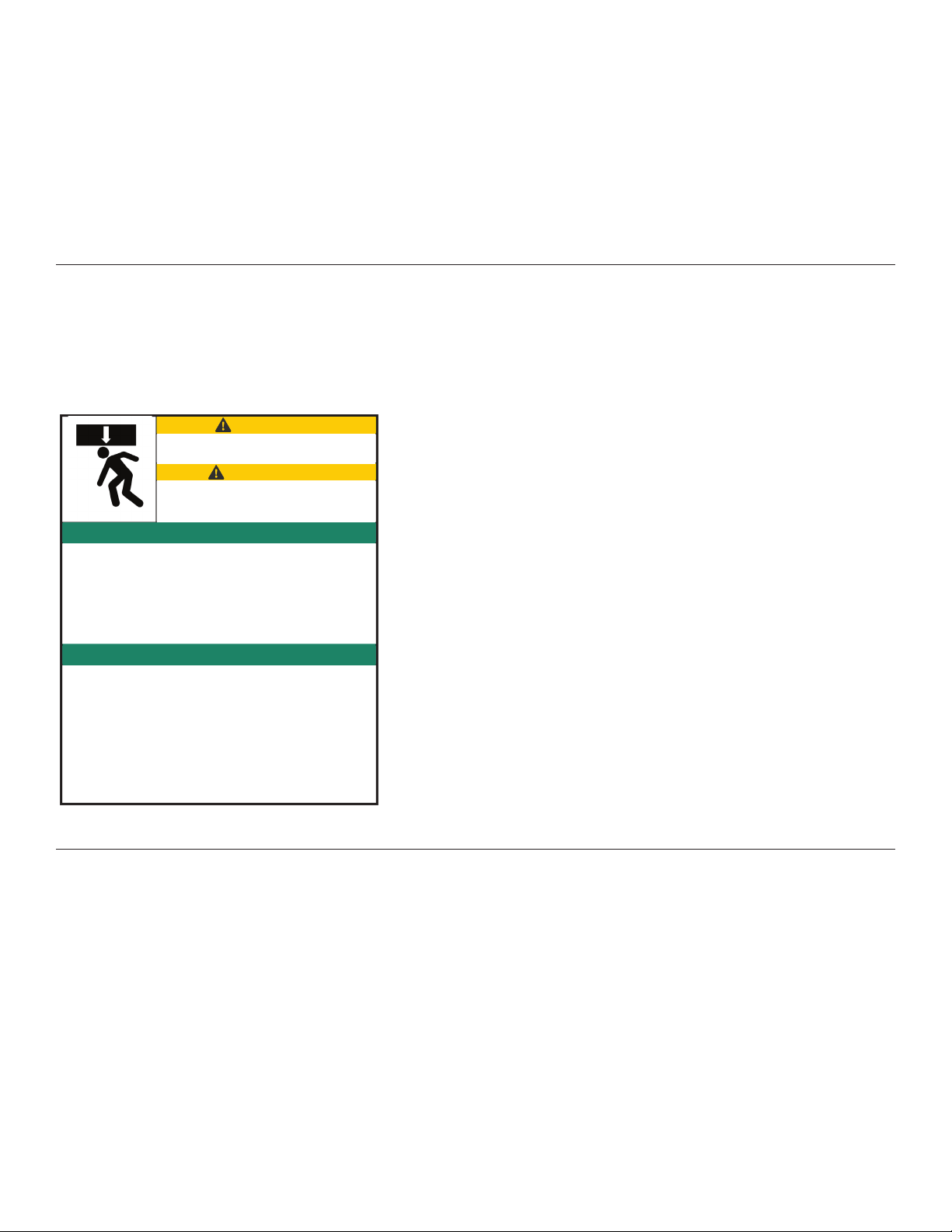
CRUSH HAZARD. Failure to properly
secure board could result in personal injury.
RISQUE D’ÉCRASEMENT. Ne pas attacher
la planche de manière sûre pourrait
entrainer des blessures personnelles.
CAUTION!
ATTENTION!
SAFETY INSTRUCTIONS
INSTRUCTIONS DE SÉCURITÉ

Page 3 of 8 | Doc # 100121 | Rev A
required materials &
equipment
10
15
14
15
18
Anchors/
Screws
47” x 48”
47” x 72”
47” x 72”
47” x 96”
47” x 96”
Size / Orientation
2
2
3
2
3
Brackets
*Table 1
Required Equipment Materials Provided
NOTE: Items are not drawn to size. Quantity of wall anchors and screws will
vary per product due to the various widths. Board size determines the quantity
of anchors and screws.*
brackets*
aura panel(s)
wall anchors*
1-1/4” self drilling screws*
• Drill
• #2 Bit
• Glass suction
cup lifters (2)
• Pliers
• Pencil
• Level
• 2 or 3-step
ladder
• Tape
measure
Before starting the installation of Aura, verify that the
required equipment is available and material provided is
accurate.
1. Provide adequate protection for finished floor
surfaces.
2. All Aura installations should be carried out by two or
more individuals. horizontal
vertical
horizontal
vertical

Page 4 of 8 | Doc # 100121 | Rev A
installation instructions
step one
Use appropriate mounting specification based on the size
and the orientation of your Aura board
NOTE: You may drill holes in the support bracket to
install into the wall stud for strongest support. Anchor
into wall studs as often as possible. Mounting heights are
recommendations only.
34 lbs
50 lbs
66 lbs
Weight
47” x 48”
47” x 72”
47” x 96”
Size
2
3
4
# of studs
Recommended Mounting Heights
A = 75-9/16” B = 46-5/8”
Horizontal Orientation
Vertical Orientation
Recommended Mounting Heights
C = 91 15/16”
D = 41 15/16”
E = 41”
F = 68 11/16”
G = 29-9/16”
H = 30 1/8”
aura 47” x 96” aura 47” x 72” aura 47” x 48”
A
B
A
B
A
B
C
D
E
F
G
H
A
B
A
B
A
B
C
D
E
F
G
H
aura 47” x 96” aura 47” x 72”
50 lbs
66 lbs
Weight
47” x 72”
47” x 96”
Size
2
2
# of studs

Page 5 of 8 | Doc # 100121 | Rev A
installation instructions
step two
A
B
A
B
A
B
C
D
E
F
G
H
Level brackets and mark holes onto wall.
Refer to recommended mounting heights
noted on page 4.
step three
Remove brackets from wall and install wall
anchors in all hole locations that are not over
a stud. Anchor may not be needed for stud.
brackets
anchors
marked hole

Page 6 of 8 | Doc # 100121 | Rev A
installation instructions
step four
Re-align brackets with holes and secure
using screws.
screws
step five
Lower brackets on back of the Aura board
onto brackets on wall.
IMPORTANT: Always check to insure both
top and bottom panel brackets are resting
on the wall brackets.
NOTE: The top and bottom of the board can
be easily identified by locating the branded
logo. The logo is applied to the bottom right
hand side of the panel.

Page 7 of 8 | Doc # 100121 | Rev A
installation instructions
step five continued
NOTE: Consider using glass suction cups
when mounting panel.
Installation of Aura is now complete.

Doc # 100121 | Rev A
Page 8 of 8
©2020 PolyVision Corporation. All rights reserved. Trademarks used herein
are the trademarks of PolyVision Corporation or their respective owner.
PolyVision Corporation reserves the right to make changes in product design,
construction or detail, and to discontinue any product or material without
notice. Tabi products are manufactured by PolyVision Corporation.
1 888 325 6351
info@tabiforteams.com
tabiforteams.com
Table of contents