Taco iWorx SMZ1 User guide

© 2015 Taco Electronic Solutions, Inc. 1
Application Guide 505-048-2
SMZ1 Hydronic Snow Melt Controller
Self-Contained Interoperable Controller Model UCP-1
SUPERSEDES: November 19, 2013 EFFECTIVE: March 10, 2015
Plant ID: 001-4165
Table of Contents
SMZ1 . . . . . . . . . . . . . . . . . . . . . . . . . . . . . . . . . . . . . . 3
Overview . . . . . . . . . . . . . . . . . . . . . . . . . . . . . . . . . 3
Features. . . . . . . . . . . . . . . . . . . . . . . . . . . . . . . . . . 3
. . . . . . . . . . . . . . . . . . . . . . . . . . . . . . . . . . . . . . . . . . . 3
Purpose of This Guide . . . . . . . . . . . . . . . . . . . . . . . . . 3
Representations and Warranties . . . . . . . . . . . . . . . . . 3
Applicable Documentation . . . . . . . . . . . . . . . . . . . . . . 4
Installation Guide . . . . . . . . . . . . . . . . . . . . . . . . . . . . . 4
General . . . . . . . . . . . . . . . . . . . . . . . . . . . . . . . . . . 4
Static Electricity . . . . . . . . . . . . . . . . . . . . . . . . . . . . 5
FCC Compliance . . . . . . . . . . . . . . . . . . . . . . . . . . . 5
Before Installing . . . . . . . . . . . . . . . . . . . . . . . . . . . . . . 5
About this Document . . . . . . . . . . . . . . . . . . . . . . . . 5
Inspecting the Equipment . . . . . . . . . . . . . . . . . . . . 5
What is Not Included with this Equipment . . . . . . . . 5
Equipment Location . . . . . . . . . . . . . . . . . . . . . . . . . 5
Selecting a Power Source . . . . . . . . . . . . . . . . . . . . 6
Installation . . . . . . . . . . . . . . . . . . . . . . . . . . . . . . . . . . 6
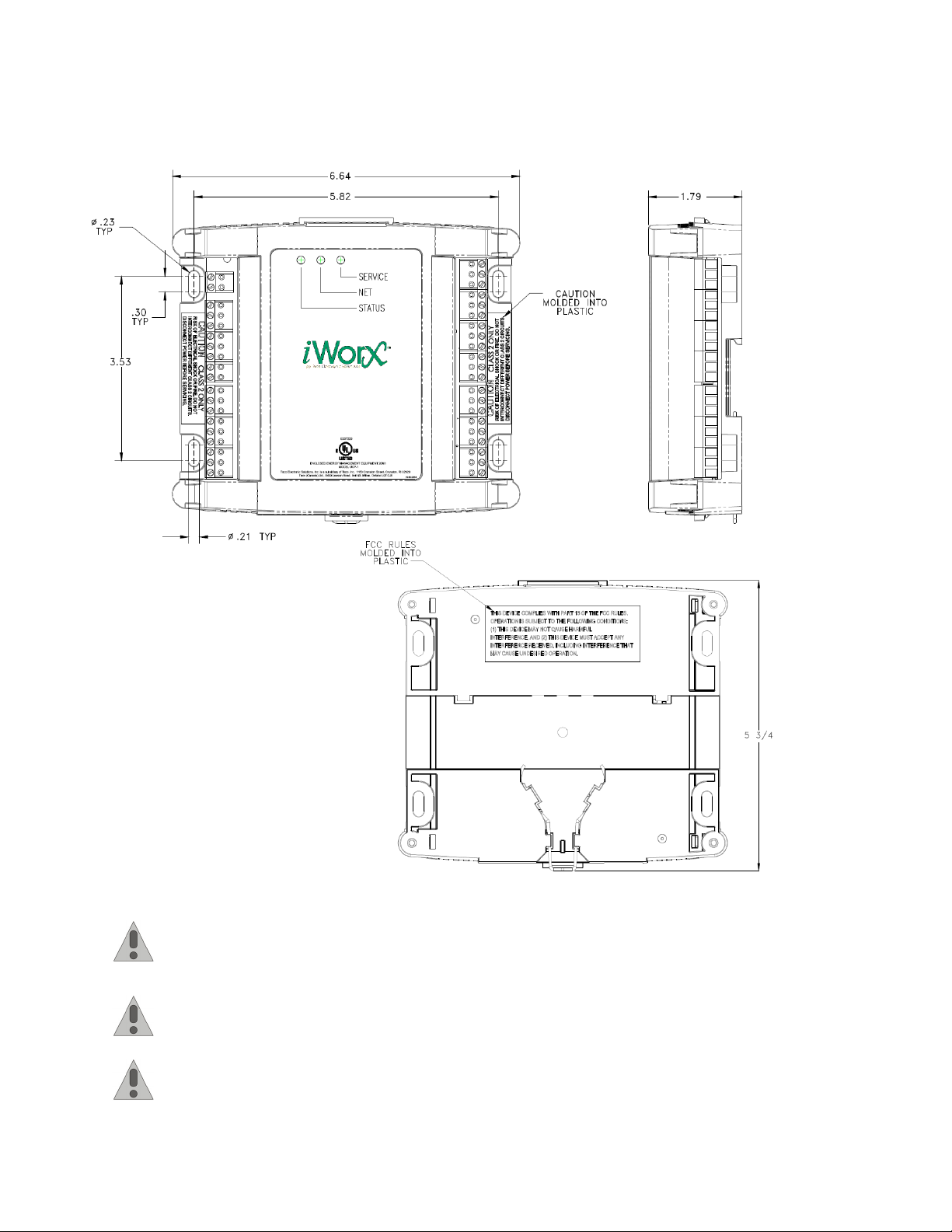
Mounting the Device . . . . . . . . . . . . . . . . . . . . . . . . 6
Routing Cabling to the Device . . . . . . . . . . . . . . . . . 7
Grounding the Device . . . . . . . . . . . . . . . . . . . . . . . 7
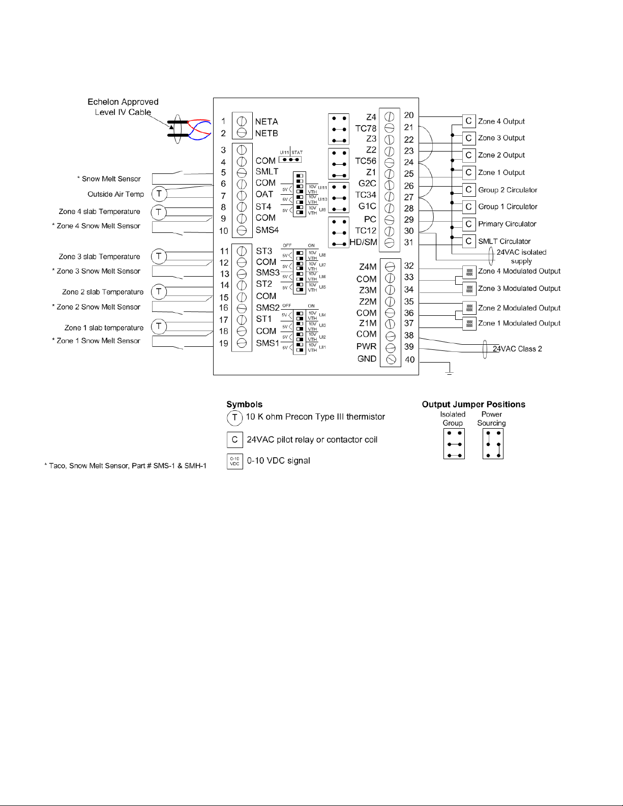
Wiring Information . . . . . . . . . . . . . . . . . . . . . . . . . . . . 8
Connecting Input Devices . . . . . . . . . . . . . . . . . . . 13
Connecting Output Devices. . . . . . . . . . . . . . . . . . 14
Other Connections. . . . . . . . . . . . . . . . . . . . . . . . . 15
Specifications . . . . . . . . . . . . . . . . . . . . . . . . . . . . . . . 15
Electrical . . . . . . . . . . . . . . . . . . . . . . . . . . . . . . . . 15
Mechanical. . . . . . . . . . . . . . . . . . . . . . . . . . . . . . . 16
Application Description. . . . . . . . . . . . . . . . . . . . . . . . 17
Sequence of Operation . . . . . . . . . . . . . . . . . . . . . . . 17
Operational Modes . . . . . . . . . . . . . . . . . . . . . . . . 17
Additional Features . . . . . . . . . . . . . . . . . . . . . . . . 18
Communication with Associated Devices . . . . . . . 19
Automatic Configuration . . . . . . . . . . . . . . . . . . . . 19
Controller Identification . . . . . . . . . . . . . . . . . . . . . . . 20
Network Inputs. . . . . . . . . . . . . . . . . . . . . . . . . . . . 20
Inputs. . . . . . . . . . . . . . . . . . . . . . . . . . . . . . . . . . . 20
Outputs . . . . . . . . . . . . . . . . . . . . . . . . . . . . . . . . . 21
Configuration . . . . . . . . . . . . . . . . . . . . . . . . . . . . . 22
Alarms . . . . . . . . . . . . . . . . . . . . . . . . . . . . . . . . . . 24
Troubleshooting . . . . . . . . . . . . . . . . . . . . . . . . . . . . . 25
Diagnostic LEDs . . . . . . . . . . . . . . . . . . . . . . . . . . 25
Troubleshooting Tips . . . . . . . . . . . . . . . . . . . . . . . 26

iWorx® SMZ1
2 505-048-2, Effective: March 10, 2015
© 2015 Taco Electronic Solutions, Inc.
THIS PAGE LEFT BLANK INTENTIONALLY

iWorx® SMZ1
505-048-2, Effective: March 10, 2015 3
© 2015 Taco Electronic Solutions, Inc.
SMZ1
The SMZ1 is a self-contained microprocessor-based controller for up to 4 snow melt zones.
Overview
The SMZ1 is a hydronic snow melt zone controller capable of regulating up to four zones. Each zone has two inputs:
one for slab temperature and one for a snow sensor. Temperature inputs are standard Precon III thermistors. The snow
sense inputs use standard dry-contact snow sensors, available from Taco. There are also Global Snow melt Enable
and Outside Air Temperature inputs. Each zone has a digital output and a modulating output suitable for valves or cir-
culators. There are also digital outputs for two Group Circulators, one Primary Circulator and Heat Demand.
The controller is based on LONWORKS® networking technology. The controller communicates with the BLM and HPM
series controllers over the network. The controller can also be networked to a higher-level control system for monitoring
and control applications.
Features
• Control of up to four snow melt zones with individual sensor inputs and isolated outputs
• Supports one 5-wire snow melt sensor
• Separate setpoints for idling and active snow melting
• Proportional plus integral (P+I) control
• Primary Pump output for a common pump or non-networked heat source
• Snow Melt Demand communicated to a BLM series boiler controller or HPM heat pump master controller
• Outdoor Air Cutoff temperature
• Configurable group circulators for assigning different heat sources to different groups of zones
• Automatic configuration with a Local Control Interface (LCI) touchscreen
• Alarm/Event Reporting
PURPOSE OF THIS GUIDE
The iWorx® SMZ1 Application Guide provides application information for the SMZ1 Controller.
The reader should understand basic HVAC concepts, intelligent environmental control automation, and basic LON-
WORKS networking and communications. This Application Manual is written for:
• Users who engineer control logic
• Users who set up hardware configuration
• Users who change hardware or control logic
• Technicians and field engineers
REPRESENTATIONS AND WARRANTIES
This Document is subject to change from time to time at the sole discretion of Taco Electronic Solutions, Inc. All
updates to the Document are available at www.taco-hvac.com. When installing this product, it is the reader’s responsi-
bility to ensure that the latest version of the Document is being used.
iWorx® products shall only be used for the applications identified in the product specifications and for no other pur-
poses. For example, iWorx® products are not intended for use to support fire suppression systems, life support sys-
tems, critical care applications, commercial aviation, nuclear facilities or any other applications where product failure
could lead to injury to person, loss of life, or catastrophic property damage and should not be used for such purposes.

iWorx® SMZ1
4 505-048-2, Effective: March 10, 2015
© 2015 Taco Electronic Solutions, Inc.
Taco Electronic Solutions, Inc. will not be responsible for any product or part not installed or operated in conformity with
the Document and instructions or which has been subject to accident, disaster, neglect, misuse, misapplication, inade-
quate operating environment, repair, attempted repair, modification or alteration, or other abuse. For further informa-
tion, please refer to the last page of this Document for the company’s Limited Warranty Statement, which is also issued
with the product or available at www.taco-hvac.com.
APPLICABLE DOCUMENTATION
INSTALLATION GUIDE
General
CAUTION: This symbol is intended to alert the user to the presence of important installation and mainte-
nance (servicing) instructions in the literature accompanying the equipment.
CAUTION: Risk of explosion if battery is replaced by an incorrect type. Contains lithium type battery; dis-
pose of properly.
WARNING: Electrical shock hazard. Disconnect ALL power sources when installing or servicing this
equipment to prevent electrical shock or equipment damage.
Make all wiring connections in accordance with these instructions and in accordance with pertinent national and local
electrical codes. Use only copper conductors that are suitable for 167 °F (75 °C).
Part Number Audience Purpose
iWorx® SMZ1 Application Guide,
Document No. 505-048-2 (this doc-
ument)
– Application Engineers
– Wholesalers
– Contractors
Provides specific application information about the
BLM series, including sequence of operation and
configuration information.
iWorx® LCI Application Guide,
Document No. 505-002
– Application Engineers
– Installers
– Service Personnel
– Start-up Technicians
– End user
Provides instructions for setting up and using the
iWorx® Local Control Interface.
iWorX BLMC Application Guide,
Document No. 505-001
– Application Engineers
– Installers
– Service Personnel
– Start-up Technicians
– End user
Provides specific application information about the
BLMC series, including sequence of operation and
configuration information.
iWorX HPM1 Application Guide,
Document No. 505-004
– Application Engineers
– Installers
– Service Personnel
– Start-up Technicians
– End user
Provides specific application information about the
DXU series, including sequence of operation and
configuration information.
http://www.iWorxWizard.com – Application Engineers
– Wholesalers
– Contractors
An on-line configuration and submittal package gen-
erator based on user input. Automatically generates
bill of materials, sequence of operations, flow dia-
grams, wiring diagrams, points and specifications.
Additional
Documentation
LonWorks FTT-10A Free Topology Transceiver User’s Guide, published by Echelon Corpora-
tion. It provides specifications and user instructions for the FTT-10A Free Topology Trans-
ceiver.

iWorx® SMZ1
505-048-2, Effective: March 10, 2015 5
© 2015 Taco Electronic Solutions, Inc.
Static Electricity
Static charges produce voltages that can damage this equipment. Follow these static electricity precautions when han-
dling this equipment.
• Work in a static free area.
• Touch a known, securely grounded object to discharge any charge you may have accumulated.
• Use a wrist strap when handling printed circuit boards. The strap must be secured to earth ground.
FCC Compliance
This equipment has been tested and found to comply with the limits for a Class A digital device, pursuant to Part 15 of
the FCC rules. These limits are designed to provide reasonable protection against harmful interference. This equip-
ment can radiate radio frequency energy and, if not installed and used in accordance with the instructions, may cause
harmful interference to radio communications. However, there is no guarantee that interference will not occur in a par-
ticular installation. If this equipment does cause harmful interference to radio or television reception, which can be
determined by turning the equipment off and on, the user is encouraged to try to correct the interference by one or
more of the following measures:
• Reorient or relocate the receiving antenna.
• Increase the separation between the equipment and the receiver.
• Connect the equipment to a power source different from that to which the receiver is connected.
• Consult the equipment supplier or an experienced radio/TV technician for help.
You are cautioned that any changes or modifications to this equipment not expressly approved in these instructions
could void your authority to operate this equipment in the United States.
BEFORE INSTALLING
About this Document
The instructions in this manual are for the SML1 module, which supports up to four snow melt zones.
Inspecting the Equipment
Inspect the shipping carton for damage. If damaged, notify the carrier immediately. Inspect the equipment for damage.
Return damaged equipment to the supplier.
What is Not Included with this Equipment
• A power source for the equipment electronics and peripheral devices.
• Tools necessary to install, troubleshoot and service the equipment.
• The screws or DIN rail needed to mount the device.
• Peripheral devices, such as sensors, actuators, etc.
• Cabling, cabling raceway, and fittings necessary to connect this equipment to the power source, FTT-10A network
and peripheral devices.
Equipment Location
Abide by all warnings regarding equipment location provided earlier in this document.
Optimally, the equipment should be installed within a secure enclosure.
The equipment must be installed indoors unless contained within a protective enclosure. The enclosure must maintain
internal temperature and humidity within the ranges specified for this equipment.

iWorx® SMZ1
6 505-048-2, Effective: March 10, 2015
© 2015 Taco Electronic Solutions, Inc.
The equipment must be installed within 500 feet of all input peripherals (smoke detectors, sensors, etc.) that will be
connected to the equipment. It must be within 200 feet of any connected thermostats.
Selecting a Power Source
This equipment requires a UL recognized external power source (not supplied) to operate. The controller power input
requires a voltage of 24 Volts AC.
To calculate power source current requirements, add the power consumption of all peripheral devices to that of the
controller.
The controller and triac output loads can use the same power source. If both are using the same power source, the
loads must have EMF protection. This protection can be integral to the load, or installed in the 24 VAC wiring across the
load’s coil.
To provide necessary RFI and transient protection, the controller’s ground (GND) pin (T40) must be connected to earth
ground or the earth ground of the packaged unit’s enclosure ground. Failure to properly ground the controller may
cause it to exceed FCC limits. Excessive noise could also produce inaccurate sensor data. The power source must be
capable of operating with this connection to ground.
INSTALLATION
Warning: Electrical shock hazard. To prevent electrical shock or equipment damage, disconnect ALL
power sources to controllers and loads before installing or servicing this equipment or modifying any wir-
ing.
Mounting the Device
1.Select a mounting location. Enclosure mounting is recommended.
2.Hold the controller on the panel you wish to mount it on. With a marker or pencil mark the mounting locations on
the panel.
3.Using a small drill bit pre-drill the mounting holes.
4.Using two #6 pan head screws, mount the controller to the panel.
5.Wire the controller (See Routing Cabling to the Device).

iWorx® SMZ1
505-048-2, Effective: March 10, 2015 7
© 2015 Taco Electronic Solutions, Inc.
Figure 1: Mounting Dimensions
Routing Cabling to the Device
Cabling used to connect the power source and cabling used to connect the FTT-10A network must remain
separated within the control enclosure and wiring conduit.
Grounding the Device
The ground terminal (T40) must be securely connected to earth ground. Failure to properly ground this
equipment will result in improper operation. Improper grounding may also increase the risk of electrical
shock and may increase the possibility of interference with radio/TV reception.
For best performance, connect the power supply common terminal (T38) to the same external point as the
ground terminal (T40).

iWorx® SMZ1
8 505-048-2, Effective: March 10, 2015
© 2015 Taco Electronic Solutions, Inc.
WIRING INFORMATION
WARNING: Terminals 12, 15, 18 and 38 are connected internally on all SMZ1 controllers. Disconnect ALL
power sources when installing or servicing this equipment to prevent electrical shock or equipment dam-
age.

iWorx® SMZ1
505-048-2, Effective: March 10, 2015 9
© 2015 Taco Electronic Solutions, Inc.
Figure 2: SMZ1 - Power Sourcing

iWorx® SMZ1
10 505-048-2, Effective: March 10, 2015
© 2015 Taco Electronic Solutions, Inc.
Figure 3: SMZ1 Power Isolated

iWorx® SMZ1
505-048-2, Effective: March 10, 2015 11
© 2015 Taco Electronic Solutions, Inc.
Figure 4: SMZ1 Global Snow Melt - Four Zones - Power Sourcing

iWorx® SMZ1
12 505-048-2, Effective: March 10, 2015
© 2015 Taco Electronic Solutions, Inc.
Figure 5: SMZ1 - Global Snow Melt - Four Zones - 5 Wire Sensor - Power Sourcing

iWorx® SMZ1
505-048-2, Effective: March 10, 2015 13
© 2015 Taco Electronic Solutions, Inc.
Figure 6: SMZ1 - Two Global Zones and Two Independent Zones - 5 Wire Sensor - Power Isolated
Connecting Input Devices
Snow Melt Sensor 1 (SMS1)
This input uses a snowmelt sensor (individual zone snowmelt mode set as “Zone Sense” or “Zone Sense With Idle”). To
connect the snowmelt sensor, attach one wire to the SMS1 (T19) and the other to the associated COM (T18).
Slab 1 Temperature (ST1)
This input uses a Precon III thermistor in the slab. To connect a thermistor, attach one wire to the ST1 (T17) input and
the other the adjacent COM (T18).
Snow Melt Sensor 2 (SMS2)
This input uses a snowmelt sensor (individual zone snowmelt mode set as “Zone Sense” or “Zone Sense With Idle”). To
connect the snowmelt sensor, attach one wire to the SMS2 (T16) and the other to the associated COM (T15).

iWorx® SMZ1
14 505-048-2, Effective: March 10, 2015
© 2015 Taco Electronic Solutions, Inc.
Slab 2 Temperature (ST2)
This input uses a Precon III thermistor in the slab. To connect a thermistor, attach one wire to the ST2 (T14) input and
the other the adjacent COM (T15).
Snow Melt Sensor 3 (SMS3)
This input uses a snowmelt sensor (individual zone snowmelt mode set as “Zone Sense” or “Zone Sense With Idle”). To
connect the snowmelt sensor, attach one wire to the SMS3 (T13) and the other to the associated COM (T12).
Slab 3 Temperature (ST3)
This input uses a Precon III thermistor in the slab. To connect a thermistor, attach one wire to the ST3 (T11) input and
the other the adjacent COM (T12).
Snow Melt Sensor 4 (SMS4)
This input uses a snowmelt sensor (individual zone snowmelt mode set as “Zone Sense” or “Zone Sense With Idle”). To
connect the snowmelt sensor, attach one wire to the SMS4 (T10) and the other to the associated COM (T9).
Slab 4 Temperature (ST4)
This input uses a Precon III thermistor in the slab. To connect a thermistor, attach one wire to the ST4 (T8) input and
the other the adjacent COM (T9).
Global Snow Melt (SMLT)
To connect a snow melt sensor to the digital input, attach one wire of the contact to SMLT (T5) and the other wire to the
adjacent COM (T6). This must be a dry contact, normally open switch.
SMLT Heater Temp (SHT)
This input is used to read the temperature of the heating element in a five-wire SMLT sensor. Connect the yellow wire
from the sensor to SHT (T3). The sensor's black ground wire should already be connected to COM.
Outdoor Air Temperature (OAT)
This input uses a Precon III thermistor. To connect a thermistor, attach one wire to the OAT (T7) input and the other the
adjacent COM (T6). Once connected, remove the controller’s cover and move the jumper W15 from Stat to UI11.
Remember to place the UI11 dip switch in the thermistor positions (Right / Left [from the bottom]). If no ASM2 is present
on the network, the OAT sensor connected to the SMZ1 is used.
Connecting Output Devices
Zone 1 Modulating Output (Z1M)
The modulated Zone 1 output is set to 0-10 V max through the control logic. Connect the positive wire from the valve or
circulator control input to Z1M (T37) and the other wire to COM (T36).
Zone 2 Modulating Output (Z2M)
The modulated Zone 2 output is set to 0-10 V max through the control logic. Connect the positive wire from the valve or
circulator control input to Z2M (T35) and the other wire to COM (T36).
Zone 3 Modulating Output (Z3M)
The modulated Zone 3 output is set to 0-10 V max through the control logic. Connect the positive wire from the valve or
circulator control input to Z3M (T34) and the other wire to COM (T33).
Zone 4 Modulating Output (Z4M)
The modulated Zone 4 output is set to 0-10 V max through the control logic. Connect the positive wire from the valve or
circulator control input to Z4M (T32) and the other wire to COM (T33).
Primary Circulator (PC)
The Primary Circulator output must be connected to a 24 VAC pilot relay if the load is greater than 1 Amp. See preced-
ing figures for details. If the load is less than 1 Amp, connect it to PC (T29) and TC12 (T30).

iWorx® SMZ1
505-048-2, Effective: March 10, 2015 15
© 2015 Taco Electronic Solutions, Inc.
Group 1 Circulator (G1C)
The Group 1 Circulator output must be connected to a 24 VAC pilot relay if the load is greater than 1 Amp. See preced-
ing figures for details. If the load is less than 1 Amp, connect it to G1C (T28) and TC34 (T27).
Group 2 Circulator (G2C)
The Group 2 Circulator output must be connected to a 24 VAC pilot relay if the load is greater than 1 Amp. See preced-
ing figures for details. If the load is less than 1 Amp, connect it to G2C (T26) and TC34 (T27).
Zone 1 Out (Z1)
The Zone 1 output must be connected to a 24 VAC pilot relay if the load is greater than 1 Amp. See preceding figures
for details. If the load is less than 1 Amp, connect it to Z1 (T25) and TC56 (T24).
Zone 2 Out (Z2)
The Zone 2 output must be connected to a 24 VAC pilot relay if the load is greater than 1 Amp. See preceding figures
for details. If the load is less than 1 Amp, connect it to Z2 (T23) and TC56 (T24).
Zone 3 Out (Z3)
The Zone 3 output must be connected to a 24 VAC pilot relay if the load is greater than 1 Amp. See preceding figures
for details. If the load is less than 1 Amp, connect it to Z3 (T22) and TC78 (T21).
Zone 4 Out (Z4)
The Zone 4 output must be connected to a 24 VAC pilot relay if the load is greater than 1 Amp. See preceding figures
for details. If the load is less than 1 Amp, connect it to Z4 (T20) and TC78 (T21).
SMLT Heater (SH)
This output is used to regulate the temperature of the heating element in a five-wire SMLT sensor. Connect the Red
wire from that sensor to SH (T3). The sensor's black ground wire should already be connected to COM.
Other Connections
Network (LON)
Network wiring must be twisted pair. One network wire must be connected to terminal NETA (T1) and the other network
wire must be connected to terminal NETB (T2). Polarity is not an issue since an FTT-10A network is used for commu-
nications.
Power (PWR)
Connect one output wire from a 24 VAC power supply to PWR (T39) and the other output wire from the power supply to
the adjacent common terminal (T38). T38 must be connected to earth ground.
Ground (GND)
Terminal GND (T40) must be connected to earth ground. Failure to properly ground this equipment will
result in improper operation. Improper grounding may also increase the risk of electrical shock, and may
increase the possibility of interference with radio and TV reception.
SPECIFICATIONS
Electrical
Inputs
• Cabling: twisted shielded pair, 18 AWG recommended—500 feet max. (152 meters)
• Resolution: 10 bit
ZoneSlab 1/2/3/4 Temperature
• Precon Type III 10K thermistor

iWorx® SMZ1
16 505-048-2, Effective: March 10, 2015
© 2015 Taco Electronic Solutions, Inc.
Global or Zone Snow Melt
• Dry Contact
• Nomally open
Outdoor Air Temperature
• Precon Type III 10K thermistor
Outputs
Zone 1/2/3/4 Modulating Output
• 0-10 VDC
Primary/Group 1/Group 2 Circulator, Zone 1/2/3/4 Out
•24VAC
• 1A @ 50C, 0.5A @ 60C, limited by the Class 2 supply rating
Power
Power Requirements
• 24VAC (20VAC to 28VAC), requires an external Class 2 supply
Power Consumption
• 7.2W with no external loads, maximum limited by the class 2 supply rating
Recommended Sensor Wire
FTT-10A Network
• Speed: 78KBPS
• 42.4 Volts DC max
• Cabling: Maximum node-to-node distance: 1312 feet (400 meters)
• Maximum total distance: 1640 feet (500 meters)
For detailed specifications, refer to the FTT-10A Free-Topology Transceiver User’s Guide published by Echelon Corpo-
ration (www.echelon.com/support/documentation/manuals/transceivers).
Mechanical
Housing
• Dimensions: 5.55” (141mm) high, 6.54” (166 mm) wide, 1.75” deep (44 mm)
• ABS
Weight
• Controller Weight: 0.70 pounds (0.32 kilograms)
• Shipping Weight: 1.0 pounds (0.46 kilograms)
Electronics
• Processor: 3150 Neuron 10 MHz
• Flash: 48 Kilobytes
• SRAM: 8 Kilobytes
Cable Type Pairs Details Taco Catalog No.
18AWG 1 Stranded Twisted Shielded Pair, Plenum WIR-018
Cable Type Pairs Details Taco Catalog No.
Level 4 22AWG (0.65mm) 1 Unshielded, Plenum, U.L. Type CMP WIR-022

iWorx® SMZ1
505-048-2, Effective: March 10, 2015 17
© 2015 Taco Electronic Solutions, Inc.
• Termination: 0.197” (5.0 mm) Pluggable Terminal Blocks, 14-22 AWG
Environmental
• Temperature: 32 °F to 140 °F (0 °C to 60 °C)
• Humidity: 0 to 90%, non-condensing
Agency Listings
• UL Listed for US and Canada, Energy Management Equipment PAZX and PAZX7.
Agency Compliances
• FCC Part 15 Class A
APPLICATION DESCRIPTION
The iWorx® SML1 is a self-contained interoperable controller for snow melting in a hydronic system. The SML1 main-
tains the temperature of up to four snow melt zones by operating valves and circulators in cooperation with a BLM
boiler controller or HPM heat pump controller. It may also be used as a stand-alone zone controller with a non-net-
worked heat source.
The temperature of each zone’s slab is controlled independently. Separate idle and melting temperature setpoints are
set for each zone.
The analog outputs for each zone are operated based on a proportional plus integral (P+I) control loop. The primary
output is turned on when any zone demand output is on. Group circulators are activated when a zone that they are
associated with has heat demand.
The SML1 may be set to communicate its heat demand to the BLM or HPM, which provides the appropriate supply
temperatures. The SML1 may be configured for a secondary loop supply, which uses the injection functions of the
BLM, or it may be set to use only the primary loop as a supply.
The commissioning switch displayed on the LCI can be set to turn on all outputs simultaneously for test purposes.
The zone valve outputs are capable of actuating 2-wire zone valves with up to 1.0 A current draw.
0-10V modulating outputs are provided for each zone to support modulating valves or circulators.
SEQUENCE OF OPERATION
This section describes the detailed sequence of operation for the SMZ1 control strategy. The italicized terms refer to
the settings available on the LCI. (See “Controller Identification” on page 20.)
Operational Modes
The SMZ1 has four distinct modes of operation.
Global Sense without Idle
When operating in Global Sense mode, the SMZ1 activates any zone when the Global Snowmelt Sensor input is active
and the zone's local slab temperature is below the slab melt setpoint temperature.
Global Sense with Idle
This mode operates similar to the Global Sense mode except it also activates when the zone slab temperature drops
below the idle temperature setpoint regardless of the state of the Global Snow Sensor.
Zone Sense without Idle
When operating in Zone Sense mode, the SMZ1 activates any zone when that zone's local Snowmelt Sensor input is
active and the zone's slab temperature is below the slab melt setpoint temperature.

iWorx® SMZ1
18 505-048-2, Effective: March 10, 2015
© 2015 Taco Electronic Solutions, Inc.
Zone Sense with Idle
This mode operates similar to the Zone Sense mode except it also activates when the zone slab temperature drops
below the idle temperature setpoint regardless of the state of the Local Snow Sensor.
Zone Output Operation
The four zone outputs may be used for zone valves or other 24 VAC-actuated heat sources. If not disabled by the out-
door limits, the outputs for each zone are operated to maintain the zone setpoints established above. The outputs are
hysteretically controlled by comparing each zone temperature (Zone 1/2/3/4 Temperature) with the respective setpoints
(Zone 1/2/3/4 Setpoint), or by a PI loop modulated output.
The status of each output is displayed on the LCI (Zone 1/2/3/4 Output).
Primary and Group Circulators
The primary circulator output is an on/off output that energizes whenever any of the four zone outputs are turned on.
Group Circulator outputs turn on whenever their associated zones are active. See Zone X Configuration for more info.
Gain Control
The analog outputs are modulated by a Proportional + Integral (P+I) control loop based on the heating loop setpoint
and the space temperature. The P+I control loop modulates the valve to maintain a constant slab temperature. As the
temperature decreases below the heating loop setpoint, the heating valve is modulated open. The heating valve is
modulated closed as the temperature increases above the heating loop setpoint.
To prevent the integral component from becoming too large, there is anti-wind up reset protection. This protection
clamps the integral value when all of the components add up to more than 100% or less than 0%.
Demand Outputs & BLM Communication
When any of the zone outputs are turned on, the Primary output is turned on. This may be used to operate a supply
pump for the zone circuits or to signal a heat demand to a non-networked boiler control or other heat source. If the
SMZ1 Heat Demand setting is on, then the status of this output is communicated to the BLM as a primary loop
demand.
The greatest of the four zone demands is displayed as the Maximum Zone Demand. If the SMZ1 Zone Demand setting
is on, this maximum value is communicated to the BLM as a sub-zone demand for the secondary loop. If the outdoor
temperature is below the OAT heating cutoff of the BLM, the BLM zone pump is operated and the injection output is
controlled to provide the appropriate outdoor reset temperature in the secondary loop. The boilers and primary pump
are operated as needed to meet the injection demand.
If the SMZ1 zones are on the secondary loop of the BLM, only the SMZ1 Zone Demand setting needs to be on, since
the demand for the boiler is dictated by the injection requirements. This method fires the boiler only as needed. How-
ever, both BLM settings, the Heat Demand and the Zone Demand may be turned on. The effect of this is to create a
demand for the boiler whenever a SMZ1 zone is calling. This serves to keep the boiler in a standby mode that could
reduce cycling as the demand from the secondary loop varies.
Additional Features
Commissioning Switch
In addition to the individual zone commissioning switches, a single switch setting can be adjusted at the LCI. By setting
Commissioning to "On,” all eight digital outputs are turned on simultaneously.
Alarm Monitoring
The controller detects certain conditions and sends them to the LCI as alarms. These alarms are displayed and
recorded for later access, but do not alter the system operation.
Temperature Sensor Alarm
If the analog input from a thermistor is outside of the expected range of the thermistor (-60 °F to 230 °F [-51 °C to 110
°C]), this alarm is sent to the LCI. An alarm of this type is most likely due to a wiring fault causing the input to be shorted
or open. An open sensor results in a reading of -60 °F (-51 °C), while a short appears as 230 °F (110 °C).

iWorx® SMZ1
505-048-2, Effective: March 10, 2015 19
© 2015 Taco Electronic Solutions, Inc.
Communication with Associated Devices
The controller is capable of communicating and sharing information with other controllers on the network.
Communication with BLM
When associated with the BLM series controllers, the SMZ1 communicates a demand for hot water. For a demand to
be received at the BLM series controller, the SMZ1 must be associated with the BLM and have the Heat Demand or
Zone Demand configuration parameter enabled.
Communication With HPM
When associated with the HPM1 water to water heat pump controller, the SMZ1 communicates a demand for hot
water. For a demand to be received at the HPM1 controller, the SMZ1 must be associated with the HPM1.
Automatic Configuration
The SMZ1 and iWorx® Local Control Interface (LCI) use a self-configuring network management scheme requiring no
external tools, binding, or LONWORKS knowledge. The LCI recognizes and configures the SMZ1 when the controller’s
service pin is pressed. The controller’s status light flashes green until the controller is configured, and is solid green
after the controller is configured. Once the service pin has been pressed, no further action is required by the user; the
controller is fully accessible to the LCI. Users may bind to SNVTs on the SMZ1 with LNS or other LONWORKS tools after
the SMZ1 has been inserted into the LCI2 network.
The LCI also provides network supervision of the SMZ1. The LCI periodically sends a "ping" message to the SMZ1,
which elicits a response. If the response fails, an alarm is displayed on the LCI. The LCI also uses the "ping" message
to refresh the occupancy mode and other system wide data.

iWorx® SMZ1
20 505-048-2, Effective: March 10, 2015
© 2015 Taco Electronic Solutions, Inc.
CONTROLLER IDENTIFICATION
Once the SMZ1 is properly installed and recognized by the LCI, the LCI touchscreen is used to configure the settings of
the controller and to monitor the Inputs, Outputs and Alarms. This section describes the commands available on the
LCI for monitoring/configuration of the SMZ1, and the meanings and suggested values for controller parameters. For
more information on using the LCI, see the iWorX LCI User’s Guide.
Network Inputs
The SMZ1 allows a network manager to write to Network Input Variables for the purpose of overriding the configuration,
operation and outputs of the SMZ1. The variables are listed below and in Table 1 on page 20.
Values written to NVIs have absolute priority over any other controller operation.
•nviOccCmd overrides the occupancy as obtained from the thermostat. Writing to this variable will also be reflected
in the controller’s output of the occupancy mode. Note that this is NOT the occupancy sensor. The occupancy sen-
sor hardware input (OCC) will still be displayed on the LCI based on its configuration.
•nviResetRuntime is a command to reset the fan, heating and cooling runtimes. If the value sent is 0, then no reset
occurs; if the value sent is 1, then the runtimes are reset.
•nviSysTime is a time stamp to set the date and time. Writing to this variable will change the time on the device and
will affect all time-related functions such as schedules.
Table 1: Network Variable Inputs (NVIs)
Inputs
This screen list all the inputs on the SMZ1. These values cannot be changed.
Internal Variable
Name Format Range Description
nviOccCmd SNVT_occupancy 0=Occupied
1=Unoccupied
2=Bypass
3=Standby
-1=Nul
Occupancy Command
NOT APPLICABLE
nviResetRuntime SNVT_lev_disc 0=no reset
1=reset runtimes
Resets fan, heating, and
cooling runtimes
nviSysTime SNVT_time_stamp Date/Time System time
Setting Range Description
Outside Temp -29 to 230 °F (-33 to 110 °C) OAT as reported from the ASM2 controller on the net-
work
Snow Melt Sensor 1
Off,
On
Status of the snow melt sensor
Snow Melt Sensor 2
Snow Melt Sensor 3
Snow Melt Sensor 4
Slab 1 Temp
-60 to 230 °F (-51 to 110 °C)
Measured temperature of each slab zone.
-60°F relates to an open sensor
230°F relates to a shorted sensor
Slab 2 Temp
Slab 3 Temp
Slab 4 Temp
Table of contents
Other Taco Controllers manuals

Taco
Taco TS-1P Original operating instructions

Taco
Taco PC705-2 User manual

Taco
Taco PC702–1 User manual

Taco
Taco 0034ePlus User manual

Taco
Taco iWorx UCP-1 User guide

Taco
Taco ZVC404-EXP-4 User manual

Taco
Taco 0034e User manual

Taco
Taco iWorX HPU2 User manual

Taco
Taco iWorx UCP-1 User guide

Taco
Taco iWorX HPU3 User manual