Tadiran Telecom EMERALD ICE User manual

TM
Emerald ICE
Digital Key
Telephone System
Hardware Installation Manual

Theinformationcontainedinthisdocumentisproprietaryandissubjecttoallrelevant
copyright,patentandotherlawsprotectingintellectualproperty,aswellasanyspecific
agreementprotectingTADIRANTELECOM,INC.(hereinreferredtoasthe“Manufacturer”)
rightsintheaforesaidinformation.Neitherthisdocumentnortheinformationcontained
hereinmaybepublished,reproducedordisclosedtothirdparties,inwholeorinpart,without
theexpress,prior,writtenpermissionoftheManufacturer.Inaddition,anyuseofthis
documentortheinformationcontainedhereinforanypurposesotherthanthoseforwhichit
wasdisclosedisstrictlyforbidden.
TheManufacturerreservestheright,withoutpriornoticeorliability,tomakechangesin
equipmentdesignorspecifications.
InformationsuppliedbytheManufacturerisbelievedtobeaccurateandreliable.However,no
responsibilityisassumedbytheManufacturerfortheusethereofnorfortherightsofthird
partieswhichmaybeaffectedinanywaybytheusethereof.
Anyrepresentation(s)inthisdocumentconcerningperformanceoftheManufacturerʹs
product(s)areforinformationalpurposesonlyandarenotwarrantiesoffutureperformance
eitherexpressorimplied.TheManufacturerʹsstandardlimitedwarranty,statedinitssales
contractororderconfirmationform,istheonlywarrantyofferedbytheManufacturerin
relationthereto.
Thisdocumentmaycontainflaws,omissionsortypesettingerrors;nowarrantyisgrantednor
liabilityassumedinrelationtheretounlessspecificallyundertakenintheManufacturerʹssales
contractororderconfirmation.Informationcontainedhereinisperiodicallyupdatedand
changeswillbeincorporatedintosubsequenteditions.Ifyouhaveencounteredanerror,
pleasenotifytheManufacturer.Allspecificationsaresubjecttochangewithoutpriornotice.
©CopyrightbyTADIRANTELECOM,INC.,2005.
Allrightsreservedworldwide.

Record of Revisions
Revision Date of Issue Supercedes Major Changes - Brief Description
initial Release March 6, 2006N/A


FEDERAL COMMUNICATIONS COMMISSION RULES
PART 68 COMPLIANCE STATEMENT
ThisequipmentcomplieswithPart68oftheFCCrules.Ontheleftsideoftheinteriorcardframe
(CoralI‐S,CoralI,andCoralIIsystems);orinsidethereardoorsontheleftsideofthecabinet
frame(CoralIIIcabinets)ofthisequipmentisalabelthatcontains,amongotherinformation,the
FCCregistrationnumberandringerequivalencenumber(REN)forthisequipment.Ifrequested,
thisinformationmustbeprovidedtothetelephonecompany.
TheRENisusedtodeterminethequantityofdeviceswhichmaybeconnectedtothetelephone
line.ExcessiveREN’sonthetelephonelinemayresultinthedevicesnotringinginresponsetoan
incomingcall.Inmost,butnotallareas,thesumoftheREN’sshouldnotexceedfive(5.0).Tobe
certainofthenumberofdevicesthatmaybeconnectedtotheline,asdeterminedbythetotal
REN’scontactthetelephonecompanytodeterminethemaximumRENforthecallingarea.
AnFCCcomplianttelephonecordandmodularplugisprovidedwiththisequipment.This
equipmentisdesignedtobeconnectedtothetelephonenetworkorpremiseswiringusinga
compatiblemodularjackwhichisPart68compliant.
Thisequipmentcannotbeusedontelephonecompany‐providedcoinservice.ConnectiontoParty
LineServiceissubjecttostatetariffs.
Ifthisequipmentcausesharmtothetelephonenetwork,thetelephonecompanywillnotifyyouin
advancethattemporarydiscontinuanceofservicemayberequired.Ifadvancenoticeisnot
practical,thetelephonecompanywillnotifythecustomerassoonaspossible.Also,youwillbe
advisedofyourrighttofileacomplaintwiththeFCCifyoubelieveitisnecessary.
Thetelephonecompanymaymakechangesinitsfacilities,equipment,operations,orprocedures
thatcouldaffecttheoperationoftheequipment.Ifthishappens,thetelephonecompanywill
provideadvancenoticeinorderforyoutomakethenecessarymodificationsinordertomaintain
uninterruptedservice.
If trouble is experienced with this equipment, please ContactTadiranTelecomat:(813)523‐0000for
repairand/orwarrantyinformation.Ifthetroubleiscausingharmtothetelephonenetwork,the
telephonecompanymayrequestyouremovetheequipmentfromthenetworkuntiltheproblemis
resolved.
Thefollowingrepairscanbedonebythecustomer:Norepairsallowed.
Thisequipmentishearing‐aidcompatible.
ItisrecommendedthatthecustomerinstallanACsurgearrestorintheACoutlettowhichthis
deviceisconnected.Thisistoavoiddamagingtheequipmentcausedbylocallightningstrikesand
otherelectricalsurges.
Thisequipmentiscapableofprovidinguser’saccesstointerstateprovidersofoperatorservices
throughtheuseofequalaccesscodes.Modificationsbyaggregatorstoalterthesecapabilitiesmay
beaviolationofthetelephoneoperatorconsumerservicesimprovementactof1990andpart68of
theFCCRules.

FEDERAL COMMUNICATIONS COMMISSION
RADIO FREQUENCY INTERFERENCE STATEMENT
TheCoralsystemgenerates,uses,andcanradiateradioenergy;and,ifnotinstalledinstrict
accordancewiththisinstallationmanual,maycauseharmfulinterferencetoradio
communications.
ThisequipmenthasbeentestedandfoundtocomplywiththelimitsforaClassAdigitaldevice,
pursuanttoSubpartJofPart15ofFCCRules,whicharedesignedtoprovidereasonable
protectionagainstsuchinterferencewhenthisequipmentisoperatedinacommercial
environment.Operationofthisequipmentinaresidentialareaislikelytocauseunacceptable
interferencetoradioandTVreception,inwhichcasetheoperatorathisownexpensewillbe
requiredtotakewhatevermeasuresmaybenecessarytocorrecttheinterference.
ToensurecontinuedcompliancewithspecifiedradioenergyemissionslimitsofFCCRules,the
followingprecautionsmustbeobservedwhileinstallingandoperatingtheequipment:
1.Installtheequipmentinstrictaccordancewiththemanufacturer’sinstructions.
2.VerifythatthepowersupplyandassociatedA.C.poweredequipmentareconnectedtoa
properlygroundedelectricalsupply,andthatpowercords,ifused,areunmodified.
3.Verifythatthesystemgrounding,includingMasterGround,D.C.powersystem,and
equipmentcabinets,isinaccordancewiththemanufacturer’sinstructionsandconnectedto
anapprovedearthgroundsource.
4.Alwaysreplacethefactory‐suppliedcoverorkeepthecabinetdoorsclosedwhennot
servicingtheequipment.
5.Makenomodificationtotheequipmentthatwouldaffectitscompliancewiththespecified
limitsofFCCRules.
6.Maintaintheequipmentinasatisfactorystateofrepair.
7.Verifythatemissionslimitingdevices,suchasferriteblocksandradiofrequency
interferencemodules,areproperlyinstalledandfunctional.
If necessary the operator should consult their Supplier,TadiranTelecom,Inc.oranexperienced
radio/televisionengineerforadditionalsuggestions.Thefollowingbookletpreparedbythe
FederalCommunicationsCommissionmaybeofassistance:“HowtoIdentifyandResolve
Radio‐TVInterferenceProblems.”ThisbookletisavailablefromtheU.S.Government
PrintingOffice,Washington,D.C.20402,StockNo.004‐000‐00345‐4.

Emerald ICE Feature Programming Manual i
TC
1 Introduction .................................................................................................... 1-1
2 System Design.................................................................................................. 2-1
2.1 Key Service Unit (KSU). . . . . . . . . . . . . . . . . . . . . . . . . . . . . . . . . . . . . . . . . . . . . . . . . . . . . . .2-1
2.2 Power Supply . . . . . . . . . . . . . . . . . . . . . . . . . . . . . . . . . . . . . . . . . . . . . . . . . . . . . . . . . . . . .2-2
2.3 Battery Charger Board (Optional). . . . . . . . . . . . . . . . . . . . . . . . . . . . . . . . . . . . . . . . . . . . . . . .2-3
2.4 CCB (Common Control Board) . . . . . . . . . . . . . . . . . . . . . . . . . . . . . . . . . . . . . . . . . . . . . . . . . .2-4
2.5 610+2 (KSU3 Component) . . . . . . . . . . . . . . . . . . . . . . . . . . . . . . . . . . . . . . . . . . . . . . . . . . . . .2-6
2.6 Base Board . . . . . . . . . . . . . . . . . . . . . . . . . . . . . . . . . . . . . . . . . . . . . . . . . . . . . . . . . . . . . .2-8
2.7 4SLT Board (Analog Port Module-4 Circuits) . . . . . . . . . . . . . . . . . . . . . . . . . . . . . . . . . . . . . . . . .2-9
2.8 12EKT (Digital Port Module - 12 Circuits) . . . . . . . . . . . . . . . . . . . . . . . . . . . . . . . . . . . . . . . . . .2-10
2.9 6CO Board (Central Office Module - 6 Circuits). . . . . . . . . . . . . . . . . . . . . . . . . . . . . . . . . . . . . . 2-11
2.10 Modem Module . . . . . . . . . . . . . . . . . . . . . . . . . . . . . . . . . . . . . . . . . . . . . . . . . . . . . . . . . .2-12
2.11 4VAA Board (4-Port Voice Automated Attendant). . . . . . . . . . . . . . . . . . . . . . . . . . . . . . . . . . . . 2-13
2.12 T1/PRI Card . . . . . . . . . . . . . . . . . . . . . . . . . . . . . . . . . . . . . . . . . . . . . . . . . . . . . . . . . . . . 2-14
2.13 Battery Charger . . . . . . . . . . . . . . . . . . . . . . . . . . . . . . . . . . . . . . . . . . . . . . . . . . . . . . . . . 2-16
2.14 Deluxe Model Telephone. . . . . . . . . . . . . . . . . . . . . . . . . . . . . . . . . . . . . . . . . . . . . . . . . . . . 2-17
2.15 Standard Model Telephone . . . . . . . . . . . . . . . . . . . . . . . . . . . . . . . . . . . . . . . . . . . . . . . . . .2-19
2.16 DSS (Direct Station Selection Terminal) . . . . . . . . . . . . . . . . . . . . . . . . . . . . . . . . . . . . . . . . . . 2-20
2.17 Expansion Boards . . . . . . . . . . . . . . . . . . . . . . . . . . . . . . . . . . . . . . . . . . . . . . . . . . . . . . . . 2-21
2.18 System Limits/Capacities . . . . . . . . . . . . . . . . . . . . . . . . . . . . . . . . . . . . . . . . . . . . . . . . . . . 2-22
2.19 Configuration Flexibility. . . . . . . . . . . . . . . . . . . . . . . . . . . . . . . . . . . . . . . . . . . . . . . . . . . . 2-28
2.20 Power Consumption Table. . . . . . . . . . . . . . . . . . . . . . . . . . . . . . . . . . . . . . . . . . . . . . . . . . .2-33
3 Installation. . . . . . . . . . . . . . . . . . . . . . . . . . . . . . . . . . . . . . . . . . . . . . . . . . . . . . . . 3-1
3.1 Installation Outline . . . . . . . . . . . . . . . . . . . . . . . . . . . . . . . . . . . . . . . . . . . . . . . . . . . . . . . . .3-1
3.2 Site Planning . . . . . . . . . . . . . . . . . . . . . . . . . . . . . . . . . . . . . . . . . . . . . . . . . . . . . . . . . . . . .3-3
4 Door Phone Installation . . . . . . . . . . . . . . . . . . . . . . . . . . . . . . . . . . . . . . . . . . . . . . . 4-1
4.1 General . . . . . . . . . . . . . . . . . . . . . . . . . . . . . . . . . . . . . . . . . . . . . . . . . . . . . . . . . . . . . . .4-1
4.2 Hardware Installation . . . . . . . . . . . . . . . . . . . . . . . . . . . . . . . . . . . . . . . . . . . . . . . . . . . . . . .4-2
4.3 Programming . . . . . . . . . . . . . . . . . . . . . . . . . . . . . . . . . . . . . . . . . . . . . . . . . . . . . . . . . . . . .4-6
5 RMP Setup . . . . . . . . . . . . . . . . . . . . . . . . . . . . . . . . . . . . . . . . . . . . . . . . . . . . . . . . 5-1
5.1 General . . . . . . . . . . . . . . . . . . . . . . . . . . . . . . . . . . . . . . . . . . . . . . . . . . . . . . . . . . . . . . .5-1
5.2 Using the RMP Setup Wizard . . . . . . . . . . . . . . . . . . . . . . . . . . . . . . . . . . . . . . . . . . . . . . . . . . .5-4
6 System Initialization . . . . . . . . . . . . . . . . . . . . . . . . . . . . . . . . . . . . . . . . . . . . . . . . . 6-1
7 T1/PRI Card Installation and Setup ........................................................................ 7-1
7.1 Description . . . . . . . . . . . . . . . . . . . . . . . . . . . . . . . . . . . . . . . . . . . . . . . . . . . . . . . . . . . . . .7-1
7.2 Installation . . . . . . . . . . . . . . . . . . . . . . . . . . . . . . . . . . . . . . . . . . . . . . . . . . . . . . . . . . . . . .7-4
7.1 RMP Setup. . . . . . . . . . . . . . . . . . . . . . . . . . . . . . . . . . . . . . . . . . . . . . . . . . . . . . . . . . . . . . .7-6
7.2 Deluxe Telephone Setup. . . . . . . . . . . . . . . . . . . . . . . . . . . . . . . . . . . . . . . . . . . . . . . . . . . . . 7-13
Emerald ICE Installation & Hardware Reference Manual 1-1
Introduction
1
1Introduction
TheTadiranEmeraldIntegratedCommunicationExchange,(ICE)isaversatile,Digital
HybridKeyTelephoneSystemthatincludesmanyadvancedfeatures.Itis
designedtomeetthetelecommunicationsneedsofsmalltomediumbusiness
offices.
TheEmeraldICEisafullydigitalhybridkeytelephonesystem.Utilizing“Loop
Start”centraloffice(TELCO)lineinterfacesinconjunctionwithanaloganddigital
extensionports,itprovidesofficecommunicationsandconnectivitytothePublic
SwitchedTelephoneNetwork(PSTN).
TheEmeraldICEoffersaplethoraofofficeproductivityfeaturesandtelephone
enhancingfeaturesthatincludeCallerIdentification(requiredTelephone
Companysubscription)inthestandardpackage.Unlikemostsystemsthatsupport
CallerID,theEmeraldICEsupportsCallerIDtoEmeraldICEproprietarydigital
extensionsandtothird‐party,CallerIDcapableanalogdevices(cordless
telephones,etc.)
Inadditiontomanystandardfeatures,severaloptionalfeaturesareofferedto
furtherenhanceofficecommunications.Thesebuilt‐invoiceprocessingintegration
packagesare:
•AutomatedAttendant
•BothFlashandHardDriveBasedVoicemail/AutoAttendant
TheEmeraldICEplatformallowstheapplicationofthesevoiceprocessing
platformswithoutlossofvaluablesystemportresources.
TheEmeraldICEiscomprisedofanapplication‐configured,expandableKey
ServiceUnitorKSUplatform.Whenusedwiththefull‐featuredDeluxeTelephone
anditsdisplay,itprovidesaccesstoallsystemfunctions.
TheEmeraldICEsystemarchitectureprovidesanexpandableinterfacefordigital
portgrowthandanalogportgrowth.Thebasicconfigurationsupportsbothdevice
types.(Analogportsmightbeusedforplainoldtelephones,faxmachines,
modems,etc.)

1-2 Emerald ICE Installation & Hardware Reference Manual
Introduction
1
AnillustrationoftheICEcabinetand2KeyTelephoneSetsareshownbelowin
Figure1.
Figure 1-1 ICE Digital
Hybrid Key Telephone
System
TheEmeraldICEincorporatesstate‐of‐the‐artdigitaltechnologyforvoiceswitching
andcallprocessingutilizingPulseCodeModulationandTimeDivision
Multiplexing(PCM/TDM).
Emerald ICE KSU Emerald ICE Deluxe Model Telephone
Emerald ICE Standard Model Telephone

Emerald ICE Installation & Hardware Reference Manual 1-3
Introduction
1
TheEmeraldICEisanon‐blockingswitchfeaturingnodegradationofvoice
signals.Thesystemutilizesa16‐bit,20MHzmainmicroprocessorandperipheral
device(extensionsandCOlines)processorsinadistributedprocessing
configuration.Memoryconsistsof640KbytesofROMand384KbytesofRAM.
TheEmeraldICEisshippedasfollows:
•1‐KSUwiththefollowing:
‐Ten(10)digitalextensionports.
‐Two(2)analogdeviceports.
‐Six(6)CIDreadyCOLineports.
‐Twomusicsourceenters(canbeassignedasdesiredtoCOlinesforhold
music/messages.
‐Onepowerfailureport(COLine1).
‐Onecontrolcontact(LBC,Gate,ExternalPageControl).
‐Oneexternalpagingequipmentinterface.
‐Twoserialports.
‐PC‐RMPProgrammingInterface.
‐SMDR(StationMessageDetailedRecording).

1-4 Emerald ICE Installation & Hardware Reference Manual
Introduction
1
About this Manual
TheEmeraldICEHardwareInstallationManualisdividedintothefollowing
sections:
•Section1‐Introduction‐thissectionprovidesageneraldescriptionofthe
EmeraldICEsystemaswellasadescriptionofthemanualcontents,associ‐
ateddocumentation,andalistingofthedocumentconventions.
•Section2‐SystemDesign‐Thissectionprovidesdescriptionsoftheindivid‐
ualcomponentsoftheEmeraldICEsystem.
•Section3‐Installation‐Thissectionprovidesinstructionsfortheinstalla‐
tionoftheKSUcabinetsandpinoutinformation.IncludesDoorPhone
Installationprocedures.
•Section4‐RMPSetup‐Thissectionprovidesinstructionsfortheinstallation
andsetupoftheEmeraldICERemoteMaintenanceandProgrammingapplica‐
tion.
•Section5‐SystemInitialization‐ThissectionprovidesDeluxeandRMP
programminginstructionsfortheinitilizationofaneworreconfigured
EmeraldICEKSU.
•Section6‐T1/PRIInstallation&Setup‐Thissectionprovidesdescriptions
oftheinstallationandsetupoftheEmeraldICET1/PRICard.

Emerald ICE Installation & Hardware Reference Manual 1-5
Introduction
1
Document Conventions
Thefollowingconventionsareusedthroughoutthismanual.
Table 1-1 Conventions
Convention Description
Normal Usedinbodytextthroughoutthismanual.
Normal,Italic Usedinreferencingsections,telephonefeatures
andvoicerecordingsorprompts.
Bold,Italic UsedindescribingthefieldsinRMPscreens
andotherformnamesoritems.
Normal,Bold Usedtodescribefilenames,devicenamesand
specificareasofRMPmenus.
Press Meanstopressaspecifickey.(e.g.pressESC
meanstopressandreleasetheEscapekey.)
Enter Meanstotypeorpushabuttononthe
telephonekeypad.
123
(TelephoneKeys)
Indicatesthekeystrokesthatarerequiredtobe
enteredonatelephone.
DISPLAY FONT IndicatesadisplayonaDeluxeModel
Telephone.

1-6 Emerald ICE Installation & Hardware Reference Manual
Introduction
1
Related Documents
Thefollowingdocumentsshouldbeusedinconjunctionwiththismanual:
• EmeraldICEProgrammingManual
• EmeraldICEDeluxeModelTelephoneUserGuide
• EmeraldICEStandardModelTelephoneUserGuide
• EmeraldICEFlashVoic emailInstallation&MaintenanceManual
• EmeraldICEHDVoicemailInstallation&MaintenanceManual

Emerald ICE Installation & Hardware Reference Manual 2-1
SystemDesign
2
2System Design
TheEmeraldICEKeyServiceUnit(KSU)isdesignedasamodularized,flat‐pack.
TwoKSU’s(KSU3andKSU4)maybeequippedtoattainthetotalsystemcapacity
of24COlines,58Extensions(46digitaland18analog)and8VoiceProcessing
Channels.EachKSUisdesignedtobemountedonthewallandisshippedwitha
wallmountingtemplate.ThecompactKSUweighslessthan20poundsandisUL
Listed.
Ifusing2KSU’s,thefirstKSU,orKSU3isfactoryequippedwithone610+2Board,
oneCCB(CommonControlBoard).ThesecondKSUorKSU4isfactoryequipped
withoneBaseBoardmodule.EachKSUisaself‐containedcabinetcontainingan
internalpowersupplyforeither117vacor230vacoperation.Atthetimeof
shippingitissetfor117vacoperation.Fromtheexterior,withcoversinplace,
KSU3andKSU4lookidentical,however,KSU3containstheCommonControl
Board(CCB).
Figure 2-1 EmeraldICE
KSU
2.1 Key Service Unit (KSU)

2-2 Emerald ICE Installation & Hardware Reference Manual
SystemDesign
2
ThepowersupplycircuitryoftheEmeraldICEincorporatesalineardesignAC
transformerwithachoiceofentervoltagetaps.Thetransformerprimarywindings
areshippedwiredfor117vacapplications.Afactoryprovidedswitchalternates
between230vacand117vacapplications.Theoutputvoltageisdeliveredtothe
610+2Board(inKSU3,BaseBoardinKSU4)forvoltageregulation.Allsystem
operationandlogicvoltagesareproducedattheseboards.
Twofusesareprovidedonthepowersupplyboard;oneforacenterover‐voltage
protectionandoneforDCoutputover‐currentprotection.Amainpowerswitchis
accessibleonthesideofeachKSU.Intheeventbatterybackupoperationis
desiredtheKSUpowercordcanbeconnectedwithanexternal(ancillary)UPS
(UninterruptiblePowerSupply).Itistheresponsibilityoftheinstallertomatchthe
batteryrequirements/UPSrequirementtothespecificneedsoftheequipment
owner.
Figure 2-2 Power
Supply
2.2 Power Supply
115V/230V Switch
KSU
2 Fuses
Main Power Switch
(Side of Cabinet)

Emerald ICE Installation & Hardware Reference Manual 2-3
SystemDesign
2
Anoptionalbatterychargercardisavailableforconnectionwiththepower
supply.Thiscardismountedonthepowersupplyvoltageregulatorusing3
suppliedstandoffs.Itprovidesathird‐party24volt,lead‐acidbatterywith.4
ampsofconstantcurrent.
Relaysonthebatterychargercarddetectvoltagesover24voltstodeactivate
charging,whileactivatingchargingforvoltageslessthan24volts.
Figure 2-3 Battery
Charger
2.3 Battery Charger Board (Optional)
To Battery
To Power Supply
Manual Shutoff

2-4 Emerald ICE Installation & Hardware Reference Manual
SystemDesign
2
TheCCBmoduleisequippedstandardinKSU3.Thisboardcontainsallcircuitry
requiredtocontrolthefullyequippedEmeraldICE.Alldigitalvoiceswitchingand
callprocessingdataswitchingisaccomplishedviatheCCB.
TheCCBhasoneribboncableconnectorforconnectiontotheKSU3610+2board
andfive(5)connectorsocketsforconnectionofthesystembuilt‐inmodem,voice
processorand2ndCabinet(KSU4).SincetheCCBcomesinstalledinsideofKSU3
theCCBribboncableisalreadyinplaceandconnectedtotheKSU3‐610+2.
AssumingtheorientationoftheKSU3cabinetisinstalledonthewall;thetwo
horizontalconnectorsocketsinthelowerleftcorneroftheCCBarefortheModem
Module.Theconnectorsocketlabeled“2ndCabinet”isforconnectiontothe
KSU4‐BaseBoardifthatexpansionisrequired.Theremainingtwoconnector
socketsontheCCB,oneattheleftside,theotherattherightsideareforthevoice
processorsolution.(Thevoiceprocessorsolutioncanbeanyofthreepossible
choices;4VAA,FlashVoicemailorHDVoicemail.)
Figure 2-4 CCB Board
2.4 CCB (Common Control Board)

Emerald ICE Installation & Hardware Reference Manual 2-5
SystemDesign
2
TheCCBalsoprovidesthefollowingstandardconnectors:
•MusicChannel1‐OnHold/BackgroundMusicInterface
•MusicChannel2‐OnHold/BackgroundMusicInterface
•ControlContact(LoudBellorExternalPageRelay)
•ExternalPagingEquipmentInterface
•RMPSerialPort‐foron‐sitedatabaseprogramming
•SMDRSerialPort‐forconnectiontoancillarySMDR/CallAccountingequip‐
ment
TheCCBhastwoOptionStrapjumpersonefordatabasestart‐up(J7)andonefor
MusicChannelOnesource(internal/external)selection(JP81).
•JP7ColdStart/Normal:JP7isusedtoforceloaddatabasedefaultfactory
settings.Thisjumperwillnormallyneverrequireoperationaftertheinitial
powerupsequenceiscompleted.Howevershouldtheneedarisetoreturn
thesitedatabasetothefactorysettingsthisjumperisusedtoaccomplishthe
task.
•JP81Internal/External:J81isusedtoselecttheMusicChannel1source.The
EmeraldICEprovidesasynthesizedmusicsourceformusiconholdinappli‐
cationswherenomusicsourceisavailable.Thesynthesizedtuneisrepeated.
JP81isinthe“External”positionwhenitshipsfromthefactory.
TheCCBisequippedwithaHeart‐beatLEDthatindicatesprocessingactivityon
thePCB.(The610+2peripheralprocessorisoperatingwhentheHeartbeatLEDis
flashing.)TheKSU3operationLED(locatednexttothepowerswitch)istiedtothe
CCBHeartbeatLED.Therefore,whentheLEDnexttothepowerswitchis
flashing,theCCBisactive..

2-6 Emerald ICE Installation & Hardware Reference Manual
SystemDesign
2
The610+2isthelargecircuitboardthatispackagedinsideofKSU3.It610+2
providesinterfaceforupto6loop‐startCOLines,10DigitalExtensionPortsand2
analogports.Additionallythe610+2regulatesthe24voltDCpowerfromthe
sourcetoproduceallrequiredlogicvoltagesandoperationsvoltages.Thereisalso
aPowerFailurePortlocatedonthe610+2thatisconnectedtothefirstCOLine
circuit.WheneverpowerfailsthisportbecomesactivewithdialtonefromtheCO
lineconnectedtothefirstCOlineport.
Figure 2-5 610+2 Board
EachCOlinecircuitonthe610+2boardincorporatesover‐voltageprotection,ring
detector,loopdetector,loop/pulse‐dialrelay,currentsinkcircuit,
coupling/isolationtransformer(impedance600:600),hybridcircuit,CODEC&
filter,polarityguardcircuitandRadioFrequencynoisefilter.
ThesixthCOLineportisequippedwithCNGFaxToneDetectioncircuitry.IfFAX
toneisdetected,thecallisroutedtotheanalogportdesignatedasthedestination
forfaxcalls.
Eachdigitalport(connectstoDeluxe&StandardTelephonesandDSSConsoles)is
comprisedofaproprietaryoctalASIC(ApplicationSpecificIntegratedCircuit)
transceiver.Therearethreedatachannelsinoperationateachdigitalportviathe
octaltransceiver.Onechannelisusedforcallprocessingcontrolofdigitalterminal
2.5 610+2 (KSU3 Component)
Other manuals for EMERALD ICE
12
Table of contents
Other Tadiran Telecom Telephone Accessories manuals

Tadiran Telecom
Tadiran Telecom EMERALD ICE Instruction Manual

Tadiran Telecom
Tadiran Telecom EMERALD ICE User manual

Tadiran Telecom
Tadiran Telecom EMERALD ICE User manual

Tadiran Telecom
Tadiran Telecom EMERALD ICE User manual

Tadiran Telecom
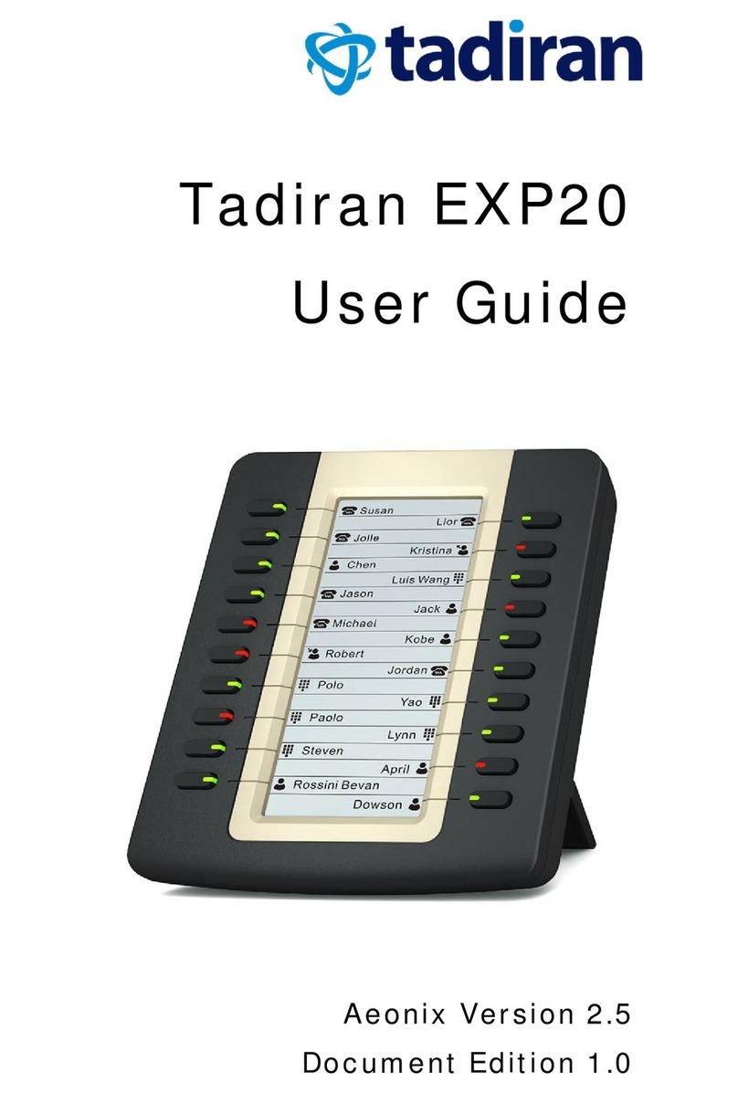
Tadiran Telecom EXP20 User manual

Tadiran Telecom
Tadiran Telecom EMERALD ICE User manual

Tadiran Telecom
Tadiran Telecom EMERALD ICE User manual