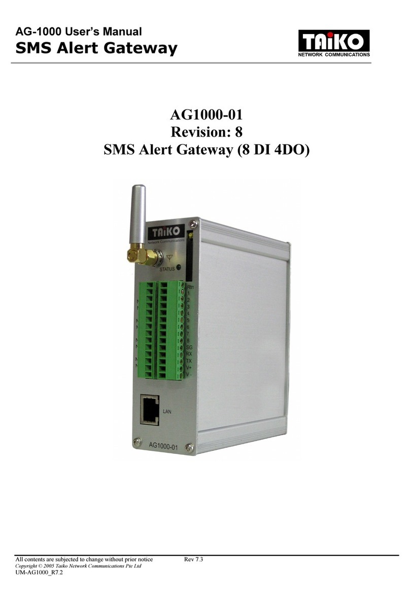
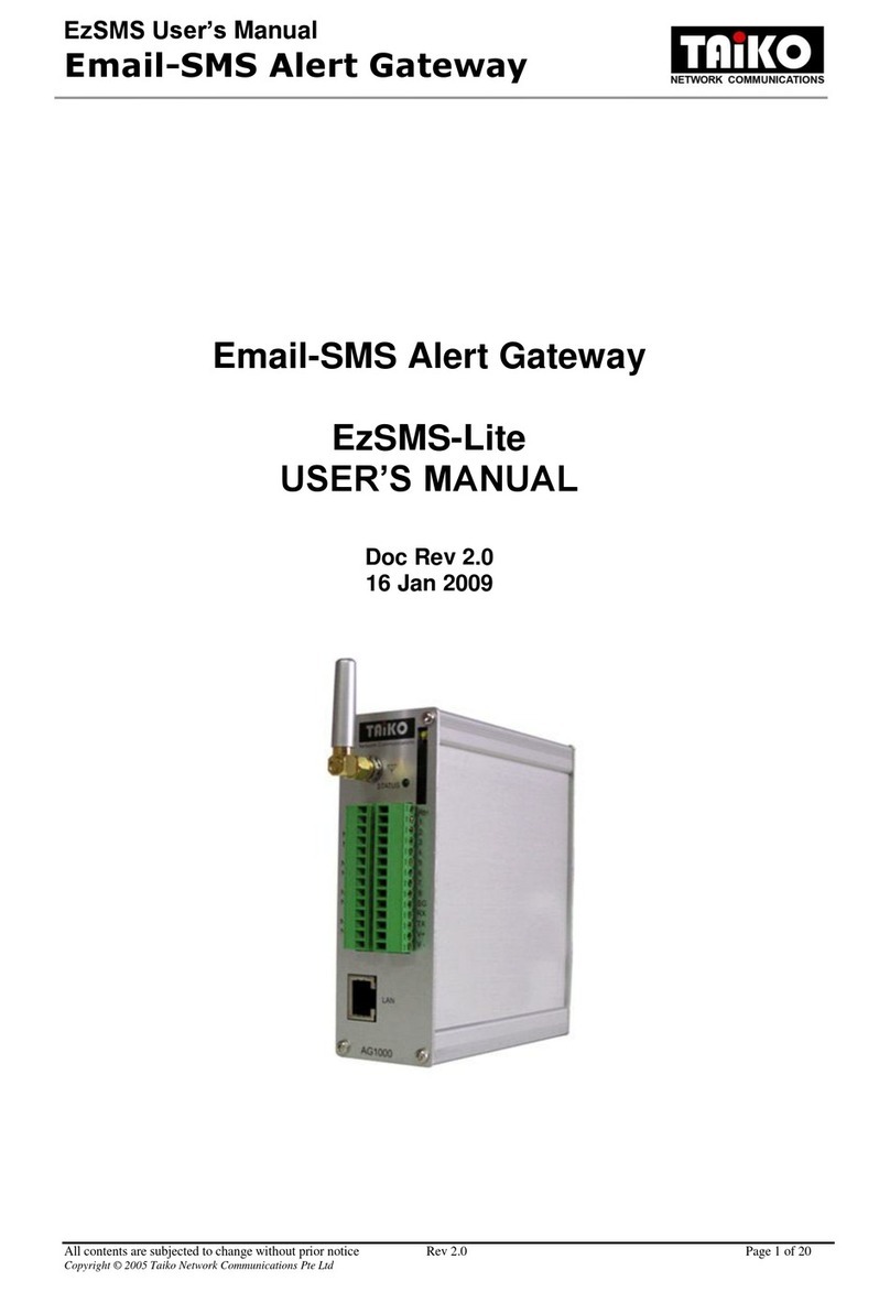
TAIKO AG-1000 User manual

AG-1000 User’s Manual
SMS Alert Gateway
All contents are subjected to change without prior notice Rev 5.0
Copyright © 2005 Taiko Network Communications Pte Ltd
UM-AG1000_R5
AG1000-01
Revision: 5.0
IO Alert SMS Gateway (8 DI 4DO)

AG-1000 User’s Manual
SMS Alert Gateway
All contents are subjected to change without prior notice Rev 5.0
Copyright © 2005 Taiko Network Communications Pte Ltd
UM-AG1000_R5
Content Page
Guidance for the manual 1
Section 1
Introduction 2
1.1
Product Overview
2
Section 2
Hardware Reference 4
2.1
Connector Description
5
2.2
Hardware Setup
6
Section 3
Software Reference 7
3.1
Installation Procedure
7
3.2
Accessing “SMS ALERT CONFIGURATION EDITOR”
7
3.3
“Handphone List” Tab
8
3.4
“Group List” Tab
9
3.5
“Point List” Tab
10
3.6
“Communication” Tab
11
3.7
File saving and retrieving
11
Section 4
Function Description 12
4.1
SMS alarming
12
4.2
Remote SMS requests
15

AG-1000 User’s Manual
SMS Alert Gateway
All contents are subjected to change without prior notice Rev 5.0
Copyright © 2005 Taiko Network Communications Pte Ltd
UM-AG1000_R5
Content Page
Appendi A
Product Specifications 17
Appendi B
SMS format list (alarm message and SMS request) 18
Appendi C
Recommended procedure for first time user 21

AG-1000 User’s Manual
SMS Alert Gateway
All contents are subjected to change without prior notice Rev 1.0 Page 1 of 22
Copyright © 2005 Taiko Network Communications Pte Ltd
Guidance for the manual
Section 1 introduces the basic feature of SMS alert gateway;
Section 2 covers the information for setting up SMS alert gateway;
Section 3 describes the functions available in configuration software, “SMS ALERT DRIVER V1.5.0”.
It includes definition for some common terms in the manual, such as alarm group, alarm setting, and
others;
Section 4 focuses on how to configure the SMS alert gateway for different requirements of alarm
condition. There are two basic alarming structures, namely broadcasting and escalating. Reminder is an
optional function for both alarming structures;
Appendix A includes all hardware specification of SMS alert gateway;
Appendix B provides a reference on the format of all recognized SMS message to SMS alert gateway.
User should refer to the format list so as to execute any desired SMS request function correctly;
Appendix C is designed for first time user in configuring SMS alert gateway. First time user is
encouraged to follow it step by step;

AG-1000 User’s Manual
SMS Alert Gateway
All contents are subjected to change without prior notice Rev 1.0 Page 2 of 22
Copyright © 2005 Taiko Network Communications Pte Ltd
Section 1 Introduction
1.1 Product Overview
SMS alert gateway is designed as a cost effective remote system alert device. It monitors up to 8 dry
contacts and 4 relay outputs. User-defined SMS is sent to pre-configured hand phone numbers when pre-
defined alarm condition happens. These pre-configured hand phone users can be any technicians or
engineers who are responsible to handle corresponding alarm. With the aid of this gateway, the alarm
condition brings attention to responsible personnel immediately. Besides it allows those hand phone
users to trigger any relay output by using SMS. The relay output can be connected with alarm indication
device, such as alarm siren, and others.
There is a built-in microprocessor chip running on a real-time operating system. It takes immediate
response to any change in both inputs and outputs condition. A GSM modem is embedded in the
gateway, user has to subscribe a SIM card for the gateway. The gateway can be installed in any location
under GSM coverage.
A software program, “SMS Alert Driver” is provided for configuring the gateway. Alert settings,
such as hand phone numbers, alert SMS message, and alarm condition is configurable through the
program. The program utilizes Ethernet connection therefore user can configure the gateway through
any computer connected within LAN. The detailed functions provided and operation conditions were
covered in the following sections of the manual.

AG-1000 User’s Manual
SMS Alert Gateway
All contents are subjected to change without prior notice Rev 1.0 Page 3 of 22
Copyright © 2005 Taiko Network Communications Pte Ltd
Functions highlight:
1. To monitor 8 dry contacts and trigger 4 relay outputs, so total 12 alarm points available;
2. User-defined alarm condition (normally close or open), alarm and recovery SMS message for each
point;
3. Maximum 10 hand phone numbers can be assigned for each point;
4. Flexible grouping of alarming level (first, second and subsequent group of hand phone number to
be notified once alarm happens) with adjustable interval delay;
5. 1 optional reminder of alarm SMS applies for all alarming level under each point;
6. User-friendly SMS service, such as requesting current status, acknowledging alarm condition of
any points and triggering relay outputs;
7. User-defined name is assigned for each point so as to implement functions in (6);
8. Administrative right can be assigned for a particular group of hand phone users. It includes remote
adding, deleting, and exchanging of hand phone numbers, activating alarming of particular point;
9. Configuration can be done remotely through LAN connection.
10. Option to extend the IO points up to 24IN and 12DO with the use of AG1000-10.

AG-1000 User’s Manual
SMS Alert Gateway
All contents are subjected to change without prior notice Rev 1.0 Page 4 of 22
Copyright © 2005 Taiko Network Communications Pte Ltd
Section 2 Hardware Reference
2.1 Connector Description
The following figure shows the front view of SMS alert gateway. All the items are marked with a unique
number followed by further description as below.
(1) Antenna
The antenna detects GSM signal for internal modem. User should tighten the antenna by turning
the bottom part marked as (1b), but not the antenna stick which is marked as (1a) in gateway figure
in previous page.
(2) IO Connector
The connector consists of voltage supply terminals, relay outputs and digital inputs connection. The
wording besides connector indicates corresponding connection:
(6)
(2)
(3)
(1a)
(4)
(1b)
(5)

AG-1000 User’s Manual
SMS Alert Gateway
All contents are subjected to change without prior notice Rev 1.0 Page 5 of 22
Copyright © 2005 Taiko Network Communications Pte Ltd
V+ 24VDC
V- GND
NC1, NC2, … , NC4
Normally open contact for relay out 1 to 4
C1, C2, …, C4 Common for relay output 1 to 4
NO1, NO2, … , NO4
Normally close contact for relay out 1 to 4
SG Common point for all digital inputs
DI1, DI2, …, DI8 Digital input 1 to 8
D+, D-, Rtn, RX. TX Unused ports
(3) SIM Card Slot
A SIM card is required for SMS alert gateway. The SIM card tray is taken out by pressing a small
button beside.
(4) Signal LED, “STATUS”
The Signal LED, “STATUS” indicates the GSM signal coverage of the SIM card. It does not light
up at all when SIM card is not detected. If SIM card is detected under GSM coverage, the LED is
flashing.
(5) DIN-rail
A DIN-rail click behind the gateway allows user to mount it on 35mm din-rail.
(6) Ethernet Port (RJ45), “ETH”
This is for Ethernet connection. The pin layout is shown as follow:
1: E_TX+
2: E_TX-
3: E_RX+
6: E_RX-
To connect with any LAN switch or hub, a UTP straight cable is required. A UTP cross cable is
used to connect with a computer Ethernet port directly.
1 8

AG-1000 User’s Manual
SMS Alert Gateway
All contents are subjected to change without prior notice Rev 1.0 Page 6 of 22
Copyright © 2005 Taiko Network Communications Pte Ltd
2.2 Hardware Setup
Connect the SMS alert gateway as the following diagram:
Insert SIM card into SIM card tray, then turn on power supply to the gateway. The Signal LED,
“STATUS” does not light up since power cycle. About 10 seconds later, it becomes flashings if the SIM
card is detected within GSM coverage. Otherwise, it remains light off. Ensure the SIM card without
locked by any PIN.
Connect Ethernet (RJ45) port, “LAN” with computer for configuration. After configuring the
gateway, unplug the cable from Ethernet port. The gateway can be installed in existing TCP network, so
it can be configured in remote area through LAN connection. For such application, the Ethernet port is
connected with ethernet switch or hub during operation period.

AG-1000 User’s Manual
SMS Alert Gateway
All contents are subjected to change without prior notice Rev 1.0 Page 7 of 22
Copyright © 2005 Taiko Network Communications Pte Ltd
Section 3 Software Reference
3.1 Installation Procedure
To install and run the “SMS ALERT DRIVER V1.5.0”, a computer has to be equipped with both
CD_ROM Drive and Ethernet Connection Port (RJ45). Insert the CD provided to the CD_ROM Drive
and choose the following directory: AG1000_800_CE. .Double click on the “Setup.exe” within the
folder. Follow the installation instruction.
3.2 Accessing “SMS ALERT CONFIGURATION EDITOR”
After finishing the installation, run the application. The following popup should appear. Please
select “AG1000-01 (8/4)”
After selecting “OK”, the configuration GUI should appear. On the GUI, mainly there are a few
main items user will need to be familiar about. Namely:
- “File” option ----- For saving and loading the configuration file.
- “Handphone List” ----- For keying in of commonly used hand phone number.
- “Group List” ----- For putting the hand phone number to the group as desired.
- “Point List” ----- To define the logic control for each of the points and which contact
group should the SMS be sent to.
- “Communication” ----- For connecting to and disconnecting from the device, uploading and
downloading of the settings, IP changing, password changing, and status
loading.

AG-1000 User’s Manual
SMS Alert Gateway
All contents are subjected to change without prior notice Rev 1.0 Page 8 of 22
Copyright © 2005 Taiko Network Communications Pte Ltd
3.3 “Handphone List” Tab
1. Key in the hand phone number including the country code into the box labeled as “HP Number”.
2. Click on insert to put the number keyed in into the list.
This list is required for later stages to be used at the grouping configuration.
“File” option
for saving and
loading
Key in user
number here
Number
will
appear
here
Click to
insert
number
to list

AG-1000 User’s Manual
SMS Alert Gateway
All contents are subjected to change without prior notice Rev 1.0 Page 9 of 22
Copyright © 2005 Taiko Network Communications Pte Ltd
3.4 “Group List” Tab
1. Select the hand phone number to be added from the list by highlighting it.
2. Check the group you want to add the number to.
3. Click on the “Insert to Group” to insert the number with the appropriate delay to the list of hand
phone settings.
4. Use the slider bar labeled “Delay to Next” to dictate any delay you might want before it sends to
the next user.
5. To delete any hand phone number, just highlight the column and press delete.
6. Group 8 is for hand phone numbers of the administrator.
Settings for the particular group of hand phone number can be configured here.
Delay to next
number settings
Settings will be
shown here
Hand phone
Number in the list
to be inserted.
Groups available
for configuration
Click on this to
insert to the group

AG-1000 User’s Manual
SMS Alert Gateway
All contents are subjected to change without prior notice Rev 1.0 Page 10 of 22
Copyright © 2005 Taiko Network Communications Pte Ltd
3.5 “Point List” Tab
1. Select the point to configure.
2. Enable - To enable a point before it can monitor the point’s status.
Alarm Logic - Select the point whether to trigger on open/close contact.
Contact Group - Select which contact group to inform if alarm is triggered.
Reminder Delay - To send a reminder SMS if alarm is triggered and not
acknowledged.
Device Name - The name user wish to assign to the point
Alarm Message - The message user wish to receive upon triggering alarm.
Normal Message - The message user wish to receive upon recovering alarm.
3. For expansion selection.
Settings for each of the points are configured here.
Settings for each
of the individual
points

AG-1000 User’s Manual
SMS Alert Gateway
All contents are subjected to change without prior notice Rev 1.0 Page 11 of 22
Copyright © 2005 Taiko Network Communications Pte Ltd
3.6 “Communication” Tab
1. Connect to the gateway (device) by an IP Address & Port.
2. Write/Read - Either to send the setting to the device or to read the setting from the
device.
Change Password - Change the password used for the connecting authentication. A pop-up
screen will be used for the input of old & new passwords. Up to 11
characters are allowed.
Change IP - Change IP Address, Netmask, & Port of the device. A disconnecting
will take place after the change.
Load Status - Load last reboot & current RTC time, modem status, number of sms,
and points status.
3. Disconnect from the device if it’s still connected.
4. Note that the device will be unable to monitor the alarm points while connected.
3.7 File saving and retrieving
To save a copy of the configuration file, select “Save” under “File” option in menu bar. The “Open”
under “File” option is for opening any pre-saved configuration file. It is good practice to save a copy
after filling up any configuration setting.
Connecting to/
disconnecting
from Gateway
IP & Port to
connect to, and
for changing to
Upload or
download
setting
Progress or
status box &
bar
Change IP
& Port.
Change
connecting
Password
Load
Gateway
status

AG-1000 User’s Manual
SMS Alert Gateway
All contents are subjected to change without prior notice Rev 1.0 Page 12 of 22
Copyright © 2005 Taiko Network Communications Pte Ltd
Section 4 Function Description
4.1 SMS alarming
In “Alarm Group” setting, the interval delay among each hand phone number is configurable. The
numbers without any delay in between is considered as one level. User can define a number of levels of
numbers according to different application consideration. If there are multiple levels of hand phone
numbers assigned to attend an alarm condition, then it is considered as escalation alarming. The delay in
between is escalation delay. Alarm SMS message is sent to first level of users immediately, but
subsequent levels in pre-defined delay. Either when alarm condition is not longer valid or some one has
acknowledged the alarm, the SMS alarming stops from further escalating. When the alarm condition is
recovered, a recovery SMS message is sent to all the hand phone users who have received the alarm
SMS message by then.
If there is only one level of hand phone numbers assigned, then it is considered as broadcasting
alarming. There is not significant delay among the SMS sending to all the numbers. The following two
examples illustrate further about these two different alarming structures:
~~~~~~~~~~~~~~~~~~~~~~~~~~~~~~~~~~~~~~~~~~~~~~~~~~~~~~~~~~~~~~~~~~~~~~~~~~~~~
Example #1: Immediate broadcasting of alarm SMS
When dry contact no.1 is closed, it will be treated as an alarm condition. Alert gateway will
then inform engineer 1 to 3 with a pre-defined alarm SMS immediately. Provided such alarm
condition is neither recovered nor acknowledged, the alert gateway will send the alarm SMS to
these three engineers in 10 minutes later as reminder.
In this example, there is only one alarming level, which consists of three engineers to attend
alarm condition of dry contact no.1, since the delay intervals among them are 0. The SMS alarming
terminates after engineer 3 receives second alarm SMS (reminder). If the reminder delay is zero,
then these engineers will only receive the first alarm SMS without any reminder. The alarming
sequence is as follow:
Point: 1
Alarm Logic: Close
Reminder: 10 (min)
Hand phone Delay
Engineer 1 0
Engineer 2 0
Engineer 3 1

AG-1000 User’s Manual
SMS Alert Gateway
All contents are subjected to change without prior notice Rev 1.0 Page 13 of 22
Copyright © 2005 Taiko Network Communications Pte Ltd
~~~~~~~~~~~~~~~~~~~~~~~~~~~~~~~~~~~~~~~~~~~~~~~~~~~~~~~~~~~~~~~~~~~~~~~~~~~~~
Example #2: Sending alarm SMS in escalating sequence
When dry contact no.1 is closed, it will be treated as an alarm condition. Alert gateway will
then inform engineer 1 to 3 with pre-defined alarm SMS immediately. Provided such alarm
condition is neither recovered nor acknowledged, the alert gateway will send the alarm SMS to
these three engineers in 10 minutes later as reminder. Unlike Example #1, SMS alarming does not
terminate after reminding these three engineers. In the next 5 minutes delay, the alert gateway
escalates its SMS alarming to supervisor 1 to 3. After 10 minutes again, similar reminder routine
applies to these three supervisors as well.
In this example, the alert gateway treats these six identities as two alarming levels because a
delay is selected between engineer 3 and supervisor 1. Therefore engineer 1 to 3 belongs to first
level, but supervisor 1 to 3 belongs to second. The alert gateway terminates SMS alarming after
Point: 1
Alarm Logic: Close
Reminder: 10 (min)
Hand phone Delay
Engineer 1 0
Engineer 2 0
1st level
Engineer 3 5
Supervisor 1 0
Supervisor 2 0
2nd
level
Supervisor 3 1

AG-1000 User’s Manual
SMS Alert Gateway
All contents are subjected to change without prior notice Rev 1.0 Page 14 of 22
Copyright © 2005 Taiko Network Communications Pte Ltd
sending second alarming SMS to supervisor 3. If the reminder delay is zero, then alert gateway will
escalate SMS alarming to second level 5 minutes after dry contact no.1 is closed. The alarming
sequence is as follow:
~~~~~~~~~~~~~~~~~~~~~~~~~~~~~~~~~~~~~~~~~~~~~~~~~~~~~~~~~~~~~~~~~~~~~~~~~~~~~
Comparing these two examples given above, there is one similarity that 1 minute is put as delay
after the last identity, such as the engineer 3 in example #1 and supervisor 3 in example #2. Any none
zero delay after the last identity is needed to enable alarming reminder for the alarming level to which
the last identity belongs. Without such 1 minutes delay, the 10 minutes reminder delay will be ignored in
example #1. Therefore, engineers 1 to 3 only receive alarming SMS once. For example #2, the alarming
reminder still applies for engineer 1 to 3 but not longer for supervisor 1 to 3. The alarming terminates
after sending one alarming SMS to supervisor 1 to 3.

AG-1000 User’s Manual
SMS Alert Gateway
All contents are subjected to change without prior notice Rev 1.0 Page 15 of 22
Copyright © 2005 Taiko Network Communications Pte Ltd
4.2 Remote SMS requests
Besides receiving alarm message in remote area, there are others useful SMS functions available for
pre-configured hand phone users.
(1) Alarm Acknowledgement:
To stop SMS alarming from further escalating or reminding, send the acknowledgement SMS to the
gateway. The format is as such: ack xxx. where xxx is the point name given to the alarm point. Upon
receiving the acknowledgement SMS, the gateway makes an announcement to all the hand phone users
who have received corresponding alarm message. These hand phone users will then receive SMS in such
format : <pt#x><xxx>acknowledged by yyy. where xindicates the point number, xxx indicates point
name and yyy is the hand phone number which sent the acknowledgement SMS.
(2) Request the current status of a contact point:
To know the current status of a contact point, send the status request SMS to the gateway. The
format is as such: get xxx. where xxx is the point name given to the contact point. The reply is in such
format: <pt#x><xxx> is open/close <normal/alarm/alarm acknowledged><yhrzmin>. where x
indicates the point number, xxx indicates point name. In the last bracket, <yhrzmin> indicates how long
the contact point has been staying on that state, either open or close.
(3) Trigger the relay output:
SMS alert gateway provides two relay outputs, which are triggered through SMS message. To
trigger one output, send SMS in such format: set xxx 1/0. where xxx indicates the point name, 1for
triggering output into alarm state, and 0to recover that output. If the relay output is connected with
normally open circuitry, then SMS message, set xxx 1 closes the output. Vice versa, the same SMS
opens the output for normally close circuitry. Upon receiving relay triggering message, SMS alert
gateway generates the following reply, <DO#x><xxx> is open/close. where xindicates the point
number, xxx indicates the point name. Power reset will take place if during receiving SMS, the gateway
has its appropriate (xxx) relay output (NC when closing or NO when opening) connecting to power.
(4) Activate\Deactivate a contact point:
Only the hand phone numbers configured as administrators is allowed to either activate or
deactivate a contact point through SMS. The SMS format is as such: act xxx 1/0. where xxx indicates
the point name, 1for activation and 0for deactivation. After deactivating a contact point, SMS alert
gateway does not send any alarm SMS whenever the point is under alarm condition.
(5) Correct the internal clock:
The internal clock of gateway can be corrected by sending SMS in such format: tim. After receiving
the SMS, gateway will synchronize its own internal clock with the actual real time clock according to

AG-1000 User’s Manual
SMS Alert Gateway
All contents are subjected to change without prior notice Rev 1.0 Page 16 of 22
Copyright © 2005 Taiko Network Communications Pte Ltd
the service provider of the SIM card inserted. Therefore, the alarm condition time is reported correctly.
This SMS function is normally used during first installation of the SMS alert gateway.
All the SMS functions provided by SMS alert gateway can be referred to Appendix B. It lists down
all the format of SMS request and corresponding reply from gateway. With the aid of such SMS
functions, user is allowed to control and monitor a equipment remotely.

AG-1000 User’s Manual
SMS Alert Gateway
All contents are subjected to change without prior notice Rev 1.0 Page 17 of 22
Copyright © 2005 Taiko Network Communications Pte Ltd
Appendix A: Product Specifications
Physical Dimension
Size 130mm x 40mm x 120mm (D X W X H)
Weight 460g
Diagnostic LEDs GSM signal, TX and RX of serial signal
Installation Method 35mm Din-Rail, desk mounts.
Environmental
Operating Temperature 10°C – 50°C
Operation Humidity 5 – 90% non-condensing
Power
Supply Voltage 7V to 30VDC
Current drawn 180mA (max)
Power consumption 1.2Wdc at 12 VDC
Connection Screw terminal
Relay Outputs (Electrical Endurance)
at 230Vac/0.5A typical 3.0x10
5
operations
at 6Vdc/0.1A typical 2.0x10
6
operations
at 30Vdc/1A typical 5.0x10
5
operations
at 30Vdc/2A typical 1.0x10
5
operations
contact rating 30Vdc/1.0A
100Vdc/0.3A
125Vac/0.5A
Ethernet Connectivity
Speed 10Base-T (RJ45 port)
GSM Standard
Antenna gain 2.15dBi (JW-X-003) / 3dBi (JW-X-010)
Bandwidth Tri-band GSM 900/1800/1900 MHz
This manual suits for next models
1
Table of contents
Other TAIKO Gateway manuals
Popular Gateway manuals by other brands

logika
logika WG-ZGWMDPB-G100-02 product manual

Crestron
Crestron Zum ZUMNET-GATEWAY quick start

Alpha Technologies
Alpha Technologies BlueGate ISDN Installation and Programming Instruction Manual

Ursalink
Ursalink LoRa manual

Pace
Pace HomePortal 5168NV Technical specifications

Viola Systems
Viola Systems arctic c-1230 quick start guide