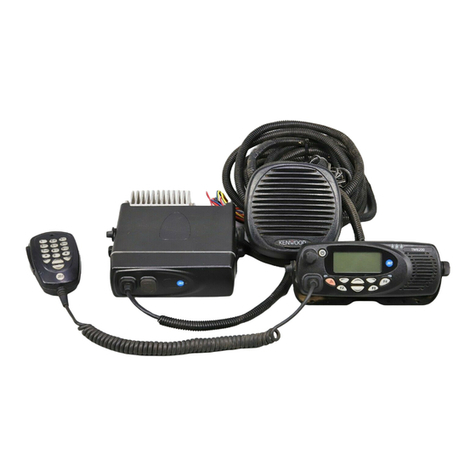
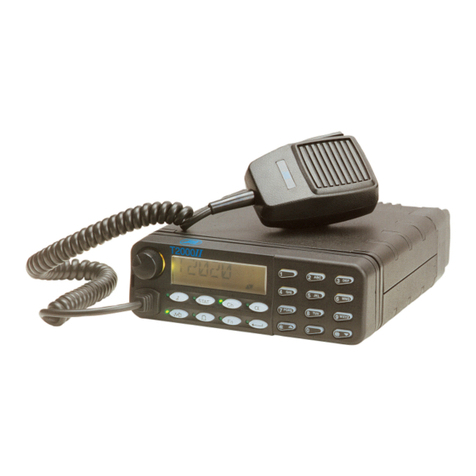
Tait TM9100 User manual

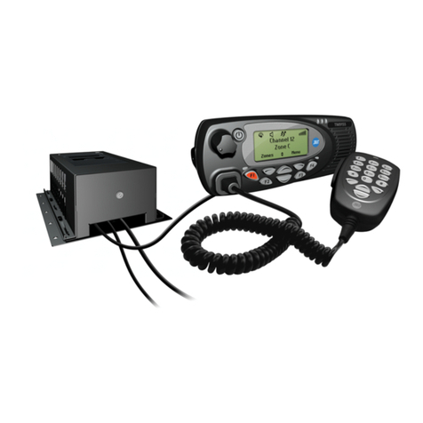
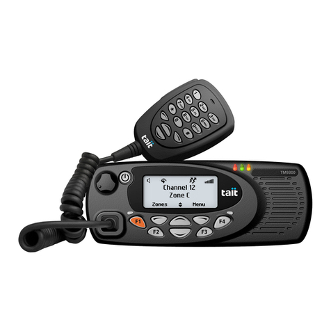
TM9100 mobiles
Service Manual
MMA-00017-01
Issue 1
August 2005

2TM9100 Service Manual
© Tait Electronics Limited August 2005
Tait Contact Information
Tait Radio Communications
Corporate Head Office
Tait Electronics Ltd
P.O. Box 1645
Christchurch
New Zealand
For the address and telephone number of
regional offices, refer to the TaitWorld
website:
Website: http://www.taitworld.com
Technical Support
For assistance with specific technical issues,
contact Technical Support:
E-mail: support@taitworld.com
Website: http://support.taitworld.com
To our European customers:
Tait Electronics Limited is an environmentally responsible company which
supports waste minimization and material recovery. The European Union’s
Waste Electrical and Electronic Equipment Directive requires that this
product be disposed of separately from the general waste stream when its
service life is over. Please be environmentally responsible and dispose
through the original supplier, your local municipal waste “separate
collection” service, or contact Tait Electronics Limited.

TM9100 Service Manual 3
© Tait Electronics Limited August 2005
Contents
Preface . . . . . . . . . . . . . . . . . . . . . . . . . . . . . . . . . . . . . . . . . . . . . . . . . 5
Scope of Manual. . . . . . . . . . . . . . . . . . . . . . . . . . . . . . . . . . . . . . . . . . . .5
Hardware and Software Versions . . . . . . . . . . . . . . . . . . . . . . . . . . . . . . . .5
Enquiries and Comments. . . . . . . . . . . . . . . . . . . . . . . . . . . . . . . . . . . . . .5
Updates of Manual and Equipment . . . . . . . . . . . . . . . . . . . . . . . . . . . . . .5
Copyright. . . . . . . . . . . . . . . . . . . . . . . . . . . . . . . . . . . . . . . . . . . . . . . . .6
Disclaimer. . . . . . . . . . . . . . . . . . . . . . . . . . . . . . . . . . . . . . . . . . . . . . . . .6
Associated Documentation. . . . . . . . . . . . . . . . . . . . . . . . . . . . . . . . . . . . .6
Publication Record. . . . . . . . . . . . . . . . . . . . . . . . . . . . . . . . . . . . . . . . . .7
Alert Notices . . . . . . . . . . . . . . . . . . . . . . . . . . . . . . . . . . . . . . . . . . . . . .7
Abbreviations . . . . . . . . . . . . . . . . . . . . . . . . . . . . . . . . . . . . . . . . . . . . . .7
Chapter 1 Description of the Radio . . . . . . . . . . . . . . . . . . . . . . . . . . . . 11
1 Introduction. . . . . . . . . . . . . . . . . . . . . . . . . . . . . . . . . . . . . . . . . . . 13
2 Description . . . . . . . . . . . . . . . . . . . . . . . . . . . . . . . . . . . . . . . . . . . 23
3 Circuit Descriptions . . . . . . . . . . . . . . . . . . . . . . . . . . . . . . . . . . . . . 63
Chapter 2 Servicing the Radio. . . . . . . . . . . . . . . . . . . . . . . . . . . . . . . . 93
4 General Information. . . . . . . . . . . . . . . . . . . . . . . . . . . . . . . . . . . . . 97
5 Disassembly and Reassembly. . . . . . . . . . . . . . . . . . . . . . . . . . . . . . 123
6 Servicing Procedures . . . . . . . . . . . . . . . . . . . . . . . . . . . . . . . . . . . 139
7 Power Supply Fault Finding . . . . . . . . . . . . . . . . . . . . . . . . . . . . . . 153
8 Interface Fault Finding . . . . . . . . . . . . . . . . . . . . . . . . . . . . . . . . . . 163
9 Frequency Synthesizer Fault Finding . . . . . . . . . . . . . . . . . . . . . . . . 169
10 Receiver Fault Finding. . . . . . . . . . . . . . . . . . . . . . . . . . . . . . . . . . 227
11 Transmitter Fault Finding (50W/40W Radios) . . . . . . . . . . . . . . . . 245
12 Transmitter Fault Finding (25W Radios). . . . . . . . . . . . . . . . . . . . . 315
13 CODEC and Audio Fault Finding. . . . . . . . . . . . . . . . . . . . . . . . . . 371
14 Fault Finding of Control Head . . . . . . . . . . . . . . . . . . . . . . . . . . . . 397
15 Spare Parts . . . . . . . . . . . . . . . . . . . . . . . . . . . . . . . . . . . . . . . . . . . 421
Chapter 3 Accessories. . . . . . . . . . . . . . . . . . . . . . . . . . . . . . . . . . . . . .427
16 TMAA02-08 Keypad Microphone . . . . . . . . . . . . . . . . . . . . . . . . . 431
17 TMAA03-02 Security Bracket . . . . . . . . . . . . . . . . . . . . . . . . . . . . 439
18 TMAA04-05 Ignition Sense Kit . . . . . . . . . . . . . . . . . . . . . . . . . . . 443
19 TMAA10-01 Desktop Microphone. . . . . . . . . . . . . . . . . . . . . . . . . 445
20 TMAA10-02 Handset. . . . . . . . . . . . . . . . . . . . . . . . . . . . . . . . . . . 449
21 TMAA10-03 and TMAA10-06 High-Power Remote Speakers . . . . 453
22 TMAA10-04 Remote PTT Kit. . . . . . . . . . . . . . . . . . . . . . . . . . . . 455
23 Installing an Enhanced Remote Kit. . . . . . . . . . . . . . . . . . . . . . . . . 461
24 TOPA-SV-024 Test Unit. . . . . . . . . . . . . . . . . . . . . . . . . . . . . . . . 477
4TM9100 Service Manual
© Tait Electronics Limited August 2005

TM9100 Service Manual 5
© Tait Electronics Limited August 2005
Preface
Scope of Manual
This manual contains information to service technicians for carrying out
level-1 and level-2 repairs of TM9100 radios and accessories.
Level-1 repairs entail the replacement of faulty parts and circuit boards;
level-2 repairs entail the repair of circuit boards, with the exception of
certain special items on the boards. The manual does not cover level-3
repairs, which entail the repair of the special items.
Hardware and Software Versions
This manual describes the following hardware and software versions.
The IPNs (internal part numbers) of theboards arelisted below; the lasttwo
digits in the IPN represent the issue of the board.
■Main board (B1 band) 50W : 220-01723-02
■Main board (H5 and H7 bands) 50W/40W : 220-01722-02
■Main board (B1 band) 25W : 220-01700-10
■Main board (H5 and H6 bands) 25W : 220-01697-10
■Control-head board : 220-01718-01
■Programming application : version 1.1.0.1
■Calibration application : version 1.0.0.0
Enquiries and Comments
If you have any enquiries regarding this manual, or any comments,
suggestions and notifications of errors, please contact Technical Support
(refer to “Tait Contact Information” on page 2).
Updates of Manual and Equipment
In the interests of improving the performance, reliability or servicing of the
equipment, Tait Electronics Ltd reserves the right to update the equipment
or this manual or both without prior notice.

6TM9100 Service Manual
© Tait Electronics Limited August 2005
Copyright
All information contained in this manual is the property of
Tait Electronics Ltd. All rights are reserved. This manual may not, in whole
or in part, be copied, photocopied, reproduced, translated, stored, or
reducedtoanyelectronic medium or machine-readableform, withoutprior
written permission from Tait Electronics Ltd.
All trade names referenced are the service mark, trademark or registered
trademark of the respective manufacturers.
Disclaimer
There are no warranties extended or granted by this manual.
Tait Electronics Ltd accepts no responsibility for damage arising from use of
the information contained in the manual or of the equipment and software
it describes. It is the responsibility of the user to ensure that use of such
information, equipment and software complies with the laws, rules and
regulations of the applicable jurisdictions.
Associated Documentation
The following associated documentation is available for this product:
■MMA-00009-xx TM9100 Product Safety and Compliance
Information
■MMA-00007-xx TM9100 User’s Guide
■MMA-00018-xx TM9100 Installation Guide
■MMA-00022-xx TM9100 Main Board (H5/H6) 25W
PCB Information
■MMA-00023-xx TM9100 Main Board (B1) 25W
PCB Information
■MMA-00024-xx TM9100 Main Board (H5/H6) 50W/40W
PCB Information
■MMA-00025-xx TM9100 Main Board (B1) 50W PCB Information
■MMA-00029-xx TM9100 Control-Head Board (Graphical Display)
PCB Information
■MMA-00026-xx TM9100 PCB Information
(printed, pre-punched and shrink wrapped;
comprises MMA-00022-xx to MMA-00025-xx and
MMA-00029-xx)
The characters xx represent the issue number of the documentation.
All available documentation is provided on the
TM9100/TP9100 Service CD, product code TMAA24-01.
Updates may also be published on the Tait support website.

TM9100 Service Manual 7
© Tait Electronics Limited August 2005
Publication Record
Alert Notices
Within this manual, four types of alerts are given to the reader: warning,
caution, important and note. The following paragraphs illustrate each type
of alert and its associated symbol.
Warning!! This alert is used when there is a potential risk
of death or serious injury.
Caution This alert is used when there is the risk of minor or
moderate injury to people.
Important This alert is used to warn about the risk of equipment dam-
age or malfunction.
Note This alert is used to highlight information that is required to
ensure that procedures are performed correctly.
Abbreviations
Issue Publication Date Description
01 August 2005 first release
Abbreviation Description
ACP Adjacent Channel Power
ADC Analog-to-Digital Converter
AGC Automatic Gain Control
ALC Automatic Level Control
APCO Association of Public Safety Communications Officials
ASC Accredited Service Center
BOM Bill of Materials
C4FM Compatible Four-level Frequency Modulation
CCTM Computer-controlled Test Mode
CODEC Coder-Decoder

8TM9100 Service Manual
© Tait Electronics Limited August 2005
CSO Customer Service Organisation
CTCSS Continuous-tone-controlled Subaudible Signaling
DAC Digital-to-Analog Converter
DC Direct Current
DSP Digital Signal Processor
DTMF Dual-Tone Multi-Frequency
EPTT External PTT (Press-To-Talk)
ESD Electrostatic Discharge
FCL Frequency Control Loop
FE Front-End
FEC Forward Error Correction
FPGA Field-Programmable Gate Array
GPIO General Purpose Input/Output
GPS Global Positioning System
GUI Graphical User Interface
IC Integrated Circuit
IPN Internal Part Number
IF Intermediate Frequency
IQ In-Phase and Quadrature
ISC International Service Center
LCD Liquid-Crystal Display
LED Light-Emitting Diode
LNA Low-Noise Amplifier
LO Local Oscillator
LPF Low-Pass Filter
NPN Negative-Positive-Negative
P25 Project 25
PA Power Amplifier
PCB Printed Circuit Board
PLL Phase-Locked Loop
PNP Positive-Negative-Positive
Abbreviation Description

TM9100 Service Manual 9
© Tait Electronics Limited August 2005
PSU Power Supply Unit
PTT Press-To-Talk
RISC Reduced Instruction Set Computing
RSSI Received Signal Strength Indication
SFE Software Feature Enabler
SMA Sub Miniature Version A
SMD Surface-Mount Device
SMT Surface-Mount Technology
SMPS Switch-Mode Power Supply
SPI Serial Peripheral Interface
TCXO Temperature-compensated Crystal Oscillator
TEL Tait Electronics Limited
VCO Voltage-Controlled Oscillator
VCXO Voltage-Controlled Crystal Oscillator
Abbreviation Description

10 TM9100 Service Manual
© Tait Electronics Limited August 2005

TM9100 Service Manual 11
© Tait Electronics Limited August 2005
TM9100mobiles
Chapter 1
Description of the Radio

12 TM9100 Service Manual
© Tait Electronics Limited August 2005
Chapter 1 – Contents
1 Introduction . . . . . . . . . . . . . . . . . . . . . . . . . . . . . . . . . . . . . . . . . . 13
1.1 Frequency Bands . . . . . . . . . . . . . . . . . . . . . . . . . . . . . . . . . . . . . . . . . . 14
1.2 RF Output Power . . . . . . . . . . . . . . . . . . . . . . . . . . . . . . . . . . . . . . . . . 14
1.3 Accessories. . . . . . . . . . . . . . . . . . . . . . . . . . . . . . . . . . . . . . . . . . . . . . . 15
1.4 Product Codes . . . . . . . . . . . . . . . . . . . . . . . . . . . . . . . . . . . . . . . . . . . . 16
1.5 Labels. . . . . . . . . . . . . . . . . . . . . . . . . . . . . . . . . . . . . . . . . . . . . . . . . . . 17
1.6 Specifications . . . . . . . . . . . . . . . . . . . . . . . . . . . . . . . . . . . . . . . . . . . . . 18
2 Description. . . . . . . . . . . . . . . . . . . . . . . . . . . . . . . . . . . . . . . . . . . 23
2.1 Mechanical Design . . . . . . . . . . . . . . . . . . . . . . . . . . . . . . . . . . . . . . . . . 23
2.3 Connectors. . . . . . . . . . . . . . . . . . . . . . . . . . . . . . . . . . . . . . . . . . . . . . . 34
2.4 Hardware and Software Architecture . . . . . . . . . . . . . . . . . . . . . . . . . . . . 42
2.5 Operation in Receive Mode . . . . . . . . . . . . . . . . . . . . . . . . . . . . . . . . . . 47
2.6 Operation in Transmit Mode . . . . . . . . . . . . . . . . . . . . . . . . . . . . . . . . . 54
3 Circuit Descriptions. . . . . . . . . . . . . . . . . . . . . . . . . . . . . . . . . . . . . 63
3.1 Transmitter Circuitry . . . . . . . . . . . . . . . . . . . . . . . . . . . . . . . . . . . . . . . 65
3.2 Receiver Circuitry . . . . . . . . . . . . . . . . . . . . . . . . . . . . . . . . . . . . . . . . . 68
3.3 Frequency Synthesizer Circuitry . . . . . . . . . . . . . . . . . . . . . . . . . . . . . . . 71
3.4 Frequency Control Loop. . . . . . . . . . . . . . . . . . . . . . . . . . . . . . . . . . . . . 75
3.5 CODEC and Audio Circuitry. . . . . . . . . . . . . . . . . . . . . . . . . . . . . . . . . 76
3.6 Power Supply Circuitry . . . . . . . . . . . . . . . . . . . . . . . . . . . . . . . . . . . . . 80
3.7 Interface Circuitry . . . . . . . . . . . . . . . . . . . . . . . . . . . . . . . . . . . . . . . . . 86
3.8 Digital Board . . . . . . . . . . . . . . . . . . . . . . . . . . . . . . . . . . . . . . . . . . . . . 88
3.9 Control-Head Board. . . . . . . . . . . . . . . . . . . . . . . . . . . . . . . . . . . . . . . . 90

TM9100 Service Manual Introduction 13
© Tait Electronics Limited August 2005
1Introduction
The TM9100 series is a range of high-performance microprocessor-
controlled radios for digital (APCO project 25-compatible), analog and
mixed operationforvoice anddatacommunication. The radios aredesigned
for installation in vehicles but can also be used in desktop, remote-
monitoring and similar applications.
This manual includes the information required for servicing the radio and
its accessories.
This section describes the different options available for:
■frequency bands
■RF output power
■accessories
■product codes
Figure 1.1 TM9155 mobile radio

14 Introduction TM9100 Service Manual
© Tait Electronics Limited August 2005
This section also gives an overview of the labels on the product and the
specifications.
1.1 Frequency Bands
The radios are available in the following frequency bands:
■136 to 174MHz (B1)
■400 to 470MHz (H5)
■450 to 530MHz (H6)
■450 to 510MHz (H7)
The frequency bandsare implementedby different main boards in the radio
body. The control heads are identical for all frequency bands.
1.2 RF Output Power
The radio bodies are available with 50W/40W and 25W RF output power.
The two RF output power options are implemented by different main
boards in the radio body, mechanically different radio bodies, and different
power connectors. The control heads are identical for all RF output power
options.
The 50W/40W radio is available in the following frequency bands:
■B1 (50W)
■H5 (40W)
■H7 (40W)
The 25W radio is available in the following frequency bands:
■B1
■H5
■H6

TM9100 Service Manual Introduction 15
© Tait Electronics Limited August 2005
1.3 Accessories
Tait offers a large variety of audio accessories, installation kits, internal
options boards and other accessories such as a desktop power supply.
For more information on these accessories refer to “Chapter 3 Accessories”
on page 427.
Audio Accessories The radios allow for the connection of a comprehensive range of audio
accessories:
■rugged microphone (standard)
■keypad microphone
■handset
■high-power remote speaker
■remote PTT kit
Installation Kits The radio is delivered with a vehicle installation kit with U-cradle.
Installation of the radio is described in the installation guide.
Optional installation kits are:
■remote control-head kit for remote installation of the control head
■security bracket for secure and quick-release installation
Internal Options
Boards The radio provides space for an internal options board inside the radio body
connecting to an internal options connector. An aperture for an external
options connector is also provided.
Desktop Power
Supply A desktop power supply including the parts for mounting the radio is
available for desktop installations.

16 Introduction TM9100 Service Manual
© Tait Electronics Limited August 2005
1.4 Product Codes
This section describes the product codes used to identify products of the
TM9100 mobile radio product line.
General The product codes of the TM9100 mobile radio product line have the
format:
TMAabc–ddee
where:
■aidentifies the product category:
A=accessory, B=radio body, C=control head, S=software feature
■b, c, dd and ee identify specific product features.
Radio Bodies The product codes of the radio bodies have the format:
TMAB3c–ddee
where:
■3identifies the architecture of the digital board:
3=APCOdigital
1 and 2 identify the digital boards of the analog TM8000 product line.
■cidentifies the RF output power:
2=25W, 4=30 to 59W, 5=30 to 59W (trigger-base)
■dd identifies the frequency band:
B1=136 to 174MHz, H5=400 to 470MHz, H6=450 to 530MHz,
H7=450 to 520MHz
Other characters identify frequency bands of the analog TM8000
product line.
■ee identifies any radio options:
00=BNC RF connector, 01=mini-UHF RF connector
Control Head The product code of the control head has the format:
TMAC41–dd
where:
■4identifies the control-head type (4=graphical-display control head)
Other numbers identify control heads of the analog TM8000 product
line.
■1identifies the control-head configuration (1=APCO digital)
0 identifies the control-head configuration of the analog TM8000
product line.
■dd identifies label and branding options.

TM9100 Service Manual Introduction 17
© Tait Electronics Limited August 2005
1.5 Labels
Four external labels are attached to the bottom of the radio body:
■compliance information
■serial number and product code
■hot surface safety warning
■RF exposure safety warning
Figure 1.2 Labels of the TM9100 product line
S/N 19061964
TMAB32-H600
450-530 MHz
Tait Electronics Ltd, NZ
Contains intellectual property licenced
by Digital Voice Systems Inc, Motorola
Inc and Tait Electronics Ltd.
Details in user documentation.
N46
IC: 737A-TMAH6C
FCC ID: CASTMAH6C
TAIT
Made in
New Zealand
TMAH6C

18 Introduction TM9100 Service Manual
© Tait Electronics Limited August 2005
1.6 Specifications
Introduction Table 1.1 shows the specifications for the TM9100 radios. The parameter
valuesquotedare minimumvalues.These specificationsare validforthedate
of publication only. For up-to-date specifications, refer to the area on the
TaitWorld website reserved for TM9100 products.
Table 1.1 Specifications
Parameter Values
Basic characteristics 50W/40W radio: 25W radio:
Frequency ranges:
•B1band
• H5 band
• H6 band
• H7 band
136 to 174MHz
400 to 470MHz
not available
450 to 520MHz
136 to 174MHz
400 to 470MHz
450 to 530MHz
not available
Channel spacing:
• B1 band
• H5, H6, H7 bands 12.5kHz/25kHz/30kHz
12.5kHz/25kHz
Channels/talkgroups (simplex or semi-duplex) 512
Frequency stability ±1.5ppm
Zones 26
Supply current:
• receive mode squelched
full audio
• transmit mode
100mA
500mA
<10A
110mA
525mA
<5.5A
RF connector 50Ωminiature UHF or BNC (optional)
Power connector:
• Power supply
• External speaker between 10.8 and 16 V DC
maximum power 10 W into 4 Ω
balanced load configuration
Interface connectors:
• microphone connector
• auxiliary connector
• internal options connector
Ports:
1 serial, 1 I/O
1 serial, 3 input, 4 I/O, 1 audio tap in, 1 audio tap out
1 serial, 7 I/O, 1 audio tap in, 1 audio tap out
Physical characteristics 50W/40W radio: 25W radio:
Weight 55.87 oz. (1.60kg) 49.47 oz. (1.40kg)
Dimensions:
•length
•width
• height
8.43 in. (214mm)
7.09 in. (180mm)
2.68 in. (68mm)
7.64 in. (194mm)
7.09 in. (180mm)
2.68 in. (68mm)

TM9100 Service Manual Introduction 19
© Tait Electronics Limited August 2005
Environmental conditions
Operating temperatures −22°F to +140°F (−30°C to +60°C)
Standards
• IP54
• MIL-STD 810C, D, E and F
(for details contact Technical Support)
Meets the requirements for sealing against:
•dust
•rain
Meets the requirements regarding the following aspects:
• low pressure
• high temperature
• low temperature
• temperature shock
•solarradiation
•rain
•humidity
• salt fog
•dust
• vibration
•shock
Receiver
Analog sensitivity (12dB SINAD) <0.25µV (−119dBm)
Digital sensitivity (TIA/EIA) 5% BER# <0.20µV (−121dBm)
Intermodulation rejection >–75dB
Adjacent channel selectivity:
• 20kHz/30kHz channel
• 12.5kHz channel >–75dB
>–65dB
Spurious responses rejection >–75dB
FM hum and noise:
• 20kHz/30kHz channel
• 12.5kHz channel >–43dB
>–40dB
Audio distortion at rated audio <3%
Audio bandwidth 300Hz to3 kHz (flat or with de-emphasis)
Receive detect time
(From the time an RF signal is first present at the
antenna to the time when the BUSY DETECT line
changes state)
< 3ms
Table 1.1 Specifications (continued)
Parameter Values

20 Introduction TM9100 Service Manual
© Tait Electronics Limited August 2005
Transmitter 50W/40W radio: 25W radio:
Output power:
• level 1 (very low)
• level 2 (low)
• level 3 (medium)
• level 4 (high)
10W
15W
25W (VHF), 20W (UHF)
50W (VHF), 40W (UHF)
1W
5W
12W
25W
Modulation limiting:
• 25kHz/30kHzchannel
• 12.5kHz channel <±5kHz
<±2.5kHz
FM hum and noise:
• 25kHz/30kHzchannel
• 12.5kHz channel >–41dB
>–37dB
Conducted and radiated emissions:
•upto1GHz
• between 1 and 4GHz
(for radio operating frequencies below 500 MHz)
• between 1 and 12.75GHz
(for radio operating frequencies above 500MHz)
<−36dBm
<−30dBm
<−30dBm
Audio bandwidth 300Hz to 3kHz (flat or with pre-emphasis)
Audio response +1/–3dB
Audio distortion <3% at 1kHz 60% modulation
Transmit rise time
(from the time the external PTT line is asserted to
the time when the RF output power reaches 90%
of its final value)
<10ms
Table 1.1 Specifications (continued)
Parameter Values
Other manuals for TM9100
8
Table of contents
Other Tait Radio manuals

Tait
Tait TM9456 Installation guide

Tait
Tait T2000 SERIES II User manual

Tait
Tait TM8100 mobiles User manual

Tait
Tait TM8250 User manual

Tait
Tait TM9315 User manual

Tait
Tait TM9100 Installation instructions

Tait
Tait T2000-300 Quick start guide

Tait
Tait TM9400 User manual

Tait
Tait TM9155R User manual

Tait
Tait TM8000 Series User manual