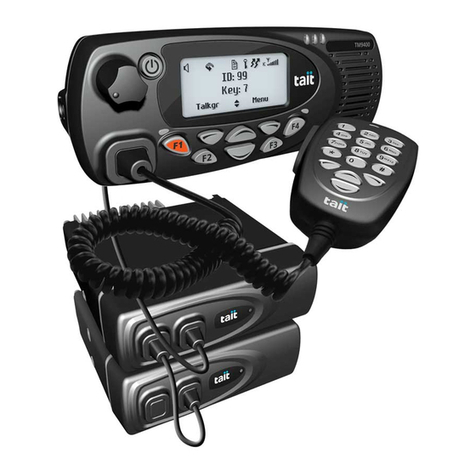
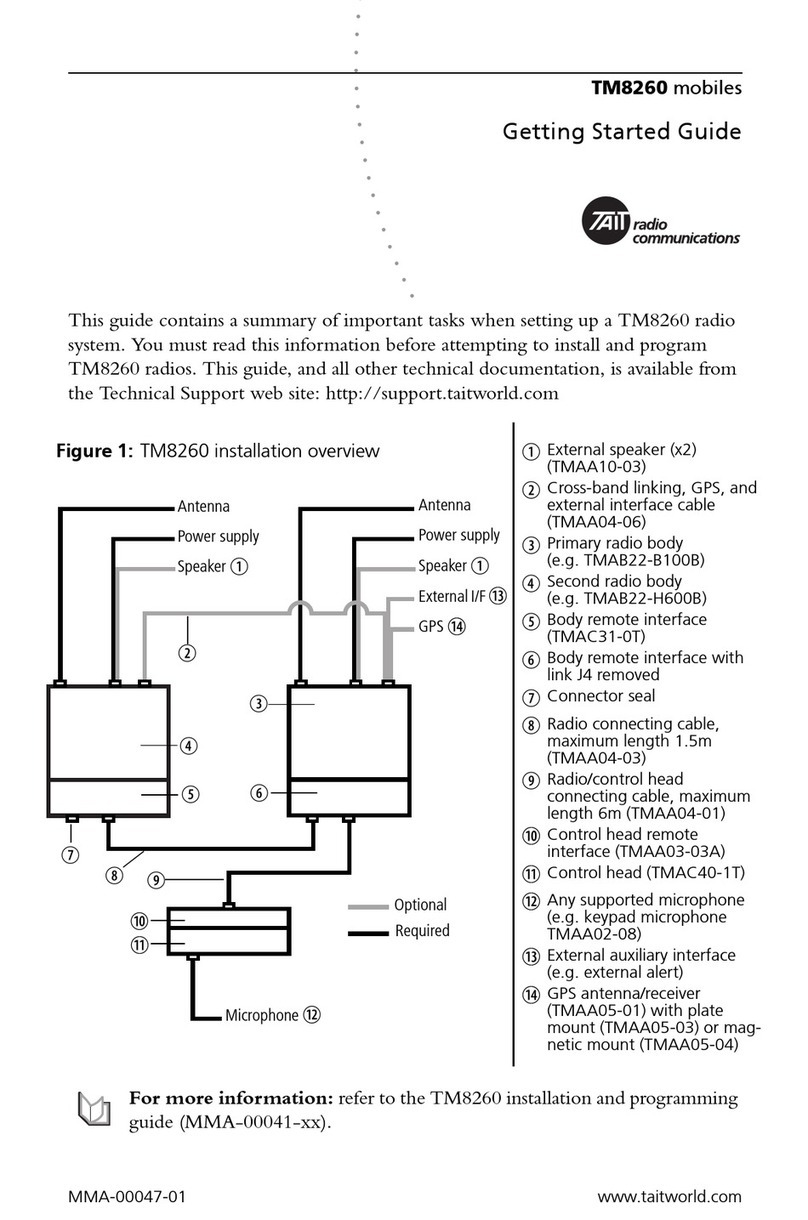
Tait TM9100 User manual

TM9100 110W Mobile Radios
Installation Guide
MMA-00039-03 · Issue 3 · October 2012

2TM9100 110W Mobile Radio Installation Guide
© Tait Limited October 2012
Contact Information
Tait Communications
Corporate Head Office
Tait Limited
P.O. Box 1645
Christchurch
New Zealand
For the address and telephone number of regional
offices, refer to our website: www.taitradio.com
Copyright and Trademarks
All information contained in this document is the
property of Tait Limited. All rights reserved.
This document may not, in whole or in part, be copied,
photocopied, reproduced, translated, stored, or reduced
to any electronic medium or machine-readable form,
without prior written permission from Tait Limited.
The word TAIT and the TAIT logo are trademarks of
Tait Limited.
All trade names referenced are the service mark,
trademark or registered trademark of the respective
manufacturers.
Disclaimer
There are no warranties extended or granted by this
document. Tait Limited accepts no responsibility for
damage arising from use of the information contained
in the document or of the equipment and software it
describes. It is the responsibility of the user to ensure
that use of such information, equipment and software
complies with the laws, rules and regulations of the
applicable jurisdictions.
Enquiries and Comments
If you have any enquiries regarding this document, or
any comments, suggestions and notifications of errors,
please contact your regional Tait office.
Updates of Manual and Equipment
In the interests of improving the performance, reliability
or servicing of the equipment, Tait Limited reserves the
right to update the equipment or this document or both
without prior notice.
Intellectual Property Rights
This product may be protected by one or more patents
or designs of Tait Limited together with their
international equivalents, pending patent or design
applications, and registered trade marks: NZ409837,
NZ409838, NZ508806, NZ508807, NZ509242,
NZ509640, NZ509959, NZ510496, NZ511155,
NZ511421, NZ516280/NZ519742, NZ520650/
NZ537902, NZ521450, NZ522236, NZ524369,
NZ524378, NZ524509, NZ524537, NZ524630,
NZ530819, NZ534475, NZ534692, NZ535471,
NZ537434, NZ546295, NZ547713, NZ569985,
NZ577009, NZ579051, NZ579364, NZ580361,
AU2003281447, AU2004216984, AU2005267973,
AU11677/2008, AU13745/2008,
CN200930004200.4, CN200930009301.0,
CN1031871, CN1070368, EU000915475-0001,
EU000915475-0002, GB2386010, GB 23865476,
GB2413249, GB2413445, US5745840, US7411461,
US7649893, US10/523952, US 10/546696, US10/
546697, US10/547964, US10/597339, US11/572700,
US29/306491, US61/218015, US61/236663, US61/
238769, US61/251372.
This product may also be made under license under one
or more of the following U.S. Patents: 4,590,473
4,636,791 4,716,407 4,972,460 5,146,497 5,148,482
5,164,986 5,185,795 5,185,796 5,271,017 5,377,229
5,502,767.
The IMBE™ voice coding Technology embodied in
this product is protected by intellectual property rights
including patent rights, copyrights and trade secrets of
Digital Voice Systems, Inc. This voice coding
Technology is licensed solely for use within this
Communications Equipment. The user of this
Technology is explicitly prohibited from attempting to
decompile, reverse engineer, or disassemble the Object
Code, or in any other way convert the Object Code
into a human-readable form. Protected by U.S. Patents
5,870,405 5,826,222 5,754,974 5,701,390 5,715,365
5,649,050 5,630,011 5,581,656 5,517,511 5,491,772
5,247,579 5,226,084 and 5,195,166.
Environmental Responsibilities
Tait Limited is an environmentally
responsible company which supports waste
minimization, material recovery and
restrictions in the use of hazardous
materials.
The European Union’s Waste Electrical and Electronic
Equipment (WEEE) Directive requires that this product
be disposed of separately from the general waste stream
when its service life is over. For more information
about how to dispose of your unwanted Tait product,
visit the Tait WEEE website at www.taitradio.com/
weee. Please be environmentally responsible and dispose
through the original supplier, or contact Tait Limited.
Tait Limited also complies with the Restriction of the
Use of Certain Hazardous Substances in Electrical and
Electronic Equipment (RoHS) Directive in the
European Union.
In China, we comply with the Measures for
Administration of the Pollution Control of Electronic
Information Products. We will comply with
environmental requirements in other markets as they are
introduced.

TM9100 110W Mobile Radio Installation Guide 3
© Tait Limited October 2012
Contents
Preface . . . . . . . . . . . . . . . . . . . . . . . . . . . . . . . . . . . . . . . . . . . . . . . . . 4
Scope of Manual. . . . . . . . . . . . . . . . . . . . . . . . . . . . . . . . . . . . . . . . . . . . . . . . . 4
Associated Documentation . . . . . . . . . . . . . . . . . . . . . . . . . . . . . . . . . . . . . . . . . 4
Publication Record. . . . . . . . . . . . . . . . . . . . . . . . . . . . . . . . . . . . . . . . . . . . . . . 4
Document Conventions . . . . . . . . . . . . . . . . . . . . . . . . . . . . . . . . . . . . . . . . . . . 5
Safety Warnings . . . . . . . . . . . . . . . . . . . . . . . . . . . . . . . . . . . . . . . . . . . 6
RF Exposure Hazard . . . . . . . . . . . . . . . . . . . . . . . . . . . . . . . . . . . . . . . . . . . . . 6
Safe Radio Mounting . . . . . . . . . . . . . . . . . . . . . . . . . . . . . . . . . . . . . . . . . . . . . 6
Correct Fuse Rating . . . . . . . . . . . . . . . . . . . . . . . . . . . . . . . . . . . . . . . . . . . . . . 6
Interference with Vehicular Electronics . . . . . . . . . . . . . . . . . . . . . . . . . . . . . . . . 7
Preparation when Drilling Holes . . . . . . . . . . . . . . . . . . . . . . . . . . . . . . . . . . . . . 7
Vehicles Powered by Liquefied Petroleum Gas. . . . . . . . . . . . . . . . . . . . . . . . . . . 7
Radio Installation in Gas or Fuel Tankers. . . . . . . . . . . . . . . . . . . . . . . . . . . . . . . 7
Negative Earth Supply . . . . . . . . . . . . . . . . . . . . . . . . . . . . . . . . . . . . . . . . . . . . 7
1 Introduction . . . . . . . . . . . . . . . . . . . . . . . . . . . . . . . . . . . . . . . . . . . 9
2 Preparing the Installation . . . . . . . . . . . . . . . . . . . . . . . . . . . . . . . . . 10
2.1 Regulations . . . . . . . . . . . . . . . . . . . . . . . . . . . . . . . . . . . . . . . . . . . . . . 10
2.2 Installation Tools. . . . . . . . . . . . . . . . . . . . . . . . . . . . . . . . . . . . . . . . . . . 10
2.3 Checking the Equipment for Completeness . . . . . . . . . . . . . . . . . . . . . . . 10
2.4 Programming Settings . . . . . . . . . . . . . . . . . . . . . . . . . . . . . . . . . . . . . . . 11
3 Installing the Radio . . . . . . . . . . . . . . . . . . . . . . . . . . . . . . . . . . . . . 12
3.1 Selecting the Mounting Position . . . . . . . . . . . . . . . . . . . . . . . . . . . . . . . 12
3.2 Installing the Antenna . . . . . . . . . . . . . . . . . . . . . . . . . . . . . . . . . . . . . . . 13
3.3 Connecting the Power Cable to the Power Source . . . . . . . . . . . . . . . . . . 14
3.4 Installing the Remote Control Head . . . . . . . . . . . . . . . . . . . . . . . . . . . . 15
3.5 Installing the Microphone . . . . . . . . . . . . . . . . . . . . . . . . . . . . . . . . . . . . 16
3.6 Connecting to the Ignition Signal . . . . . . . . . . . . . . . . . . . . . . . . . . . . . . 17
3.7 Connecting a Remote Speaker . . . . . . . . . . . . . . . . . . . . . . . . . . . . . . . . 18
3.8 Connecting to an Emergency Switch and/or External Alert Devices . . . . . 19
3.9 Mounting the Radio . . . . . . . . . . . . . . . . . . . . . . . . . . . . . . . . . . . . . . . . 21
3.10 Checking the Installation . . . . . . . . . . . . . . . . . . . . . . . . . . . . . . . . . . . . . 22
Tait Software License Agreement . . . . . . . . . . . . . . . . . . . . . . . . . . . . . . 23

4Preface TM9100 110W Mobile Radio Installation Guide
© Tait Limited October 2012
Preface
Scope of Manual
This manual describes how to install a TM9100 110W mobile radio,
including microphone, antenna, emergency switch, and external alert
device.
The installation of accessories is described in the installation instructions
provided with the equipment, and the relevant section in the service
manual.
Associated Documentation
The following associated documentation is available for this product:
■MTA-00011-xx Safety and Compliance Information
■MMA-00078-xx TM9135 User’s Guide
■MMA-00007-xx TM9155 User’s Guide
■MMA-00017-xx TM9100 Service Manual
Technical notes are published from time to time to describe applications for
Tait products, to provide technical details not included in manuals, and to
offer solutions for any problems that arise.
All available TM9100 product documentation is provided on the CD
supplied with the service kit1. Updates may also be published on the Tait
support website.
Publication Record
1. Technical notes are only available in PDF format from the Tait support
website. Consult your nearest Tait Dealer or Customer Service Organiza-
tion for more information.
Issue Publication Date Description
1 December 2005 First release
2 November 2006 Installing a remote speaker procedure
amended
3 October 2012 New Tait logo

TM9100 110W Mobile Radio Installation Guide Preface 5
© Tait Limited October 2012
Document Conventions
Please follow exactly any instruction that appears in the text as an ‘alert’.
An alert provides necessary safety information as well as instruction in the
proper use of the product. This manual uses the following types of alert:.
Warning This alert is used when there is a hazardous situa-
tion which, if not avoided, could result in death or serious
injury.
Caution This alert is used when there is a hazardous situation which,
if not avoided, could result in minor or moderate injury.
Notice This alert is used to highlight information that is required to
ensure procedures are performed correctly. Incorrectly performed proce-
dures could result in equipment damage or malfunction.
This icon is used to draw your attention to information that may improve
your understanding of the equipment or procedure.

6 Safety Warnings TM9100 110W Mobile Radio Installation Guide
© Tait Limited October 2012
Safety Warnings
This section contains important information on the safe installation of the
radio. You must read this information before starting the installation.
You must also read and observe the safety information on radio operation
provided in the Safety and Compliance Information and the User’s Guide.
RF Exposure Hazard
Radios produce RF electromagnetic energy when transmitting and this can
be hazardous to human health. The 110 W mobile has a very powerful
transmitter, requiring that particular care is taken to ensure that exposure to
RF energy is kept below the limits defined in FCC guidelines.
Warning RF exposure hazard. To comply with FCC RF
exposure limits, mount the antenna at a location such that no
person or persons can come closer than 44 inches (1.1m) to the
antenna. For VHF radios, mount the antenna centrally on the
vehicle roof, with a gain of 2.15dBi or 5.15dBi.
Warning When installing and testing this radio, DO NOT
allow the antenna to touch or come very close to any part of
your body while the radio is transmitting.
Safe Radio Mounting
Warning Mount the radio securely so that it will not break
loose in the event of a collision. An unsecured radio is dangerous
to the vehicle occupants.
■Do not mount the radio vertically.
Correct Fuse Rating
Warning Danger of fire. The radio’s protection mechanisms
rely on the correct fuses on both the negative and positive power
supply leads being present. Failure to fit the correct fuses may
result in fire or damage to the radio.
Use the following fuse type:
■30A fuse (Tait IPN 265-00012-00)

TM9100 110W Mobile Radio Installation Guide Safety Warnings 7
© Tait Limited October 2012
Interference with Vehicular Electronics
Warning Some vehicular electronic devices may be prone to
malfunction due to the lack of protection from RF energy when
your radio is transmitting.
Examples of vehicular electronic devices that may be affected by RF
energy are:
■electronic fuel injection systems
■electronic anti-skid braking systems
■electronic cruise control systems
■indicators.
If the vehicle contains such equipment, consult the vehicle manufacturer or
dealer to determine whether these electronic circuits will perform normally
when the radio is transmitting.
Preparation when Drilling Holes
Warning When drilling holes in the vehicle, check that drill-
ing at the selected points will not damage existing wiring, fuel
tanks, fuel lines, brake pipes, or battery cables.
Vehicles Powered by Liquefied Petroleum Gas
Warning Radio installation in vehicles powered by LPG
(liquefied petroleum gas) with the LPG container in a sealed-off
space within the interior of the vehicle must conform to the
National Fire Protection Association Standard NFPA 58.
This standard states that the radio equipment installation must
meet the following requirements:
■The space containing the radio equipment shall be
isolated by a seal from the space containing the LPG
container and its fitting.
■Outside filling connections shall be used for the LPG
container and its fittings.
■The LPG container space shall be vented to the outside of
the vehicle.
Radio Installation in Gas or Fuel Tankers
Special conditions must be observed when installing a radio on gas and fuel
tankers. Consult your radio provider or Tait-accredited service center for
more details.
Negative Earth Supply
The radios are designed to operate only in a negative earth system.

8 Safety Warnings TM9100 110W Mobile Radio Installation Guide
© Tait Limited October 2012

TM9100 110W Mobile Radio Installation Guide Introduction 9
© Tait Limited October 2012
1 Introduction
The TM9100 110W mobile radio is a P25-compliant radio in the VHF
(136-174MHz) frequency range with 110W transmit power output.
It consists of a standard TM9100 mobile enclosed in a strong chassis on top
of which is an external RF amplifier. The TM9100 110W mobile radio
comes complete with remote control head, microphone, and install kit.
An optional base plate and cover provide secure ‘quick-release’ mounting
and additional protection against water and physical impact. The TM9100
110W mobile radio is already fitted with an ignition sense kit.
The TM9100 110W mobile radio is designed to be trunk-mounted, with
the remote control head mounted in the vehicle cabin.

10 Preparing the Installation TM9100 110W Mobile Radio Installation Guide
© Tait Limited October 2012
2 Preparing the Installation
This section contains the following information to assist you in preparing for
the actual installation:
■regulations
■installation tools
■checking the equipment for completeness
■programming settings.
2.1 Regulations
MPT 1362 Code of
Practice TM9100 mobile radios should be installed in accordance with the
MPT 1362 Code of Practice.
Vehicle
Manufacturer’s
Installation
Guidelines
Follow your vehicle manufacturer’s guidelines for installing mobile radios.
For more information, contact the vehicle manufacturer’s dealer or refer to
the vehicle manufacturer’s website, for example, http://service.gm.com/
techlineinfo/radio.html (General Motors) or http://www.fordemc.com/
docs/download/Mobile_Radio_Guide.pdf (Ford).
2.2 Installation Tools
The following tools are required to install the radio:
■drill and drill bits
■Pozidriv screwdr iver
■RF connector crimp tool
■fuse crimp tool
■in-line RF power meter capable of measuring forward and reflected
power at the operating frequency of the radio
2.3 Checking the Equipment for Completeness
Unpack the radio and check that you have the following:
■RF amplifier and radio body
■base plate (optional)
■cover (optional)
■control head (with fitting instructions)
■microphone
■remote cable
■installation kit.
Before installing, make sure that cable lengths are sufficient

TM9100 110W Mobile Radio Installation Guide Preparing the Installation 11
© Tait Limited October 2012
2.4 Programming Settings
Make sure that the radio has been correctly programmed before installing it.
The radio can only be programmed via the control head microphone
socket, not via the sockets on the dual RJ-45 head.
In particular, programming must have done the following:
■Selected the B1 band (Specifications form).
■Enabled the check box ‘Configure as 110W radio’ (Specifications form).
This modifies the setting of a number of items, including the power
output to the external RF amplifier.
■Configured the channels that the radio will operate on (Channels form).
■Configured the AUX_GPI3 line for ignition sense (Programmable I/O
form, Digital tab), as follows:
■Pin: AUX_GPI3
■Direction: Input
■Action: Power Sense (Ignition)
■Active: High.
Refer to the online help of the programming application for more
information.
■Configured any inputs and outputs on the auxiliary connector that will
be used for external devices or signals (Programmable I/O form).
Notice Incorrect programming settings can result in damage to the
external RF amplifier.
Refer to the online help of the programming application for more
information.

12 Installing the Radio TM9100 110W Mobile Radio Installation Guide
© Tait Limited October 2012
3 Installing the Radio
This section explains how to install and check the radio and its associated
equipment. It contains the following information:
■selecting the mounting position
■installing the antenna
■connecting the power cable to the power source
■installing the remote control head
■installing the microphone
■connecting to the ignition signal
■connecting a remote speaker
■connecting to an emergency switch and/or external alert devices
■mounting the radio
■checking the installation.
3.1 Selecting the Mounting Position
Inspect the vehicle and determine the safest and most convenient position
for mounting the radio. Tait recommends the use of an equipment
mounting tray designed for the vehicle. These are available from
manufacturers such as Havis-Shields (www.havis.com), Jotto Desk
(www.jottodesk.com), Gamber Johnson (www.gamberjohnson.com), and
Stewart Products (www.stewartproducts.com).
Make sure that there is sufficient clearance for the cables. Check cable
lengths. Make sure that there is a gap of at least 1 inch (2.5cm) for the
heatsink and that air can flow freely around it.
Notice Do not mount the radio in areas where it can be sprayed by a
high-pressure cleaning device or temporarily submerged from an accu-
mulation of water or other liquids.

TM9100 110W Mobile Radio Installation Guide Installing the Radio 13
© Tait Limited October 2012
3.2 Installing the Antenna
This section provides information on installing an external antenna within
the RF exposure limits.
Install the external antenna (not supplied) according to the antenna
manufacturer’s instructions. Good quality 50 Ωcoaxial cable must be used,
such as RG58 or UR76.
Notice Route the cable in a manner that minimizes:
■coupling into the electronic control systems of the vehicle
■coupling of electric vehicle systems, such as alternators, into the
radio.
Avoid sharp bends in the cable. These distort the cable and alter its
electrical characteristics.
Warning RF exposure hazard. To comply with FCC RF
exposure limits, mount the antenna at a location such that no
person or persons can come closer than 44 inches (1.1m) to the
antenna. For VHF radios, mount the antenna centrally on the
vehicle roof, with a gain of 2.15dBi or 5.15dBi.
Terminating the
Antenna Cable 1. Run the antenna cable (not supplied) from the antenna to the radio
mounting location and cut it to length, allowing approximately eight
inches (20 cm) excess at the radio end.
2. Strip the end of the coaxial cable as shown in Figure 3.1. Fit the right
angle N-type antenna connector (supplied) to the antenna cable.
Figure 3.1 Stripping the antenna cable
0.83 in
(21 mm)
0.33 in
(8.3 mm)
0.27 in
(6.8 mm)
0.24 in
(6.0 mm)

14 Installing the Radio TM9100 110W Mobile Radio Installation Guide
© Tait Limited October 2012
3.3 Connecting the Power Cable to the Power Source
Power is supplied to the 110W mobile via a cable with a DB15 connector
(provided). This plugs into the external RF amplifier, which provides power
to the back of the radio body via an internal loom.
Notice This radio is designed to operate from a nominal 12V negative
ground supply and may draw up to 30A of current. The radio will tol-
erate a supply voltage range of 10.8V to 16.6V at the radio.
Selecting the Power
Source In passenger vehicles, the radio is always connected directly to the battery.
In trucks, where direct connection to the battery is often not possible, the
radio can be connected to a suitable terminal inside the fuse box that is
connected directly to the battery.
24V-to-12V
Converter In vehicles with a supply voltage larger than 16.0V, such as many trucks, it
is essential to provide a suitably rated 24V-to-12V converter. This will
isolate the radio from excessive battery voltage and provide the correct DC
operating conditions. Note that most 24V-to-12V converters already fitted
are not rated sufficiently.
Standby Current When using the ignition signal to turn off the radio, the standby current is
reduced to <3mA. Otherwise, the standby current is 50mA.
Connecting the
Power Cable Notice Although it is possible to connect the radio in line with the
vehicle ignition, this is not recommended, as it may draw too much cur-
rent and damage the vehicle wiring and steering column or ignition
switch. This may also cause the supply voltage of the radio to drop below
the specified level.
Notice Disconnecting the vehicle’s battery may cause problems with
some electronic equipment, such as vehicle alarms, engine management
systems, and in-car entertainment systems. Check that the vehicle owner
has the necessary information to make all electronic equipment function
correctly after battery reconnection.
Notice If the battery is not disconnected, exercise extreme caution
during the installation and install the fuses only when the installation is
ready to be checked. For more information, refer to “Checking the
Installation” on page 22.
1. Disconnect the vehicle’s battery unless specifically prohibited from
doing so by the customer, vehicle manufacturer, agent, or supplier.
Notice Route the cable in a manner that minimizes coupling of elec-
tric vehicle systems such as alternators into the radio.
Notice Protect the power cable from engine heat, sharp edges and
from being pinched or crushed.

TM9100 110W Mobile Radio Installation Guide Installing the Radio 15
© Tait Limited October 2012
2. Run the supplied power cable (or one with a higher current rating)
between the radio’s mounting position and the vehicle battery (12V)
and cut it to length, allowing approximately 8 inches (20 cm) excess
at the radio end.
3. Cut the negative (black) and the positive (red) wires where the in-line
fuse holders will be placed (as close to the power source as possible).
Notice Do not install the fuses until the installation is ready to be
checked. For more information, refer to “Checking the Installation” on
page 22.
4. Insert each end of the negative wire into each of the fuse
crimp-terminals and crimp them to force the metal contacts onto
the wires.
5. Push the two crimp-terminals into the clear plastic fuse cover. Close
the cover while the next steps are completed.
6. Repeat steps 4 and 5 for the positive wire.
7. Connect the negative wire to the battery ground terminal.
8. Connect the positive wire to the battery positive terminal.
Notice Do not install the fuses until the installation is ready to be
checked. For more information, refer to “Checking the Installation” on
page 22.
3.4 Installing the Remote Control Head
1. Choose a suitable location for the control head.
2. Mount the control head according to the instructions supplied (IPN
402-00020-xx). Make sure that you follow the warnings and cautions
in these instructions.
The remote control head back (TMAA03-03) has already been fitted to
the control head and the dual RJ-45 torso interface (TMAC34-1T) has
already been fitted to the radio body.)
3. Run the remote head cable (TMAA04-01) from the control head
location to the radio mounting location.

16 Installing the Radio TM9100 110W Mobile Radio Installation Guide
© Tait Limited October 2012
3.5 Installing the Microphone
This section describes the radio’s microphone connector and the information
required to connect the microphone and install the microphone clip.
Notice The microphone grommet must be installed whenever the
microphone is plugged into the microphone socket:
■to prevent damage to the microphone socket when there is
movement of the microphone cord
■to ensure that the control head is sealed against water, dust and
other environmental hazards.
Connecting the
Microphone 1. Plug the microphone into the microphone socket.
2. Slide the grommet along the microphone cord and push two adjacent
corners of the grommet into the microphone socket cavity.
3. Squeeze the grommet and push the remaining corners into position.
4. Check that the grommet is seated correctly in the cavity.
Installing the
Microphone Clip Install the microphone clip in the most convenient location using the screws
provided. The microphone must be within reach of the user but in such a
position that the PTT (press-to-talk) key cannot be inadvertently activated
or jammed.
Warning Safe microphone mounting. Mount the micro-
phone where it will not interfere with:
■the deployment of passenger airbags
■the vehicle operator controls
■the vehicle operator’s view.
Notice Only install the microphone clip provided. If a non-standard
microphone clip is used, the correct operation of the microphone hook-
switch cannot be guaranteed.
Figure 3.2 Correct microphone and remote cable grommet seating
microphone
grommet
control head

TM9100 110W Mobile Radio Installation Guide Installing the Radio 17
© Tait Limited October 2012
3.6 Connecting to the Ignition Signal
Ignition sense allows the radio to be turned on and off with the ignition key
of the vehicle. The TM9100 110W mobile radio is already fitted with an
ignition sense kit, however it must be programmed for ignition sense
operation.
If ignition sense operation is desired:
1. Make sure that the AUX GP13 line has been programmed for igni-
tion sense.
2. Run the yellow wire from the back of the mobile body (underneath
the 110W RF Amplifier) to a 12V signal controlled by the ignition
key.
3. Secure the cable with cable ties using the small holes in the side of the
chassis.
The logic thresholds for AUX GPI3 are based on 3V3 levels. However,
AUX GPI3 can be connected directly to a +13.8V ignition signal.
Figure 3.3 Holes for cable ties
Holes for cable ties

18 Installing the Radio TM9100 110W Mobile Radio Installation Guide
© Tait Limited October 2012
3.7 Connecting a Remote Speaker
If a high-power remote speaker is required, Tait recommends using the
TMAA10-03 high-power remote speaker for 25W radios. Installation
instructions (IPN 402-00010-xx) are provided with the speaker.
If a different speaker is used, it can be connected to the flying-lead connector
already installed in the power connector (b), or connected using the two
spare receptacles that are provided with the installation kit (c).
1. Run the speaker cable to the radio, then (underneath the RF ampli-
fier) alongside the ignition sense cable to the back of the radio body.
2. Secure the speaker cable with cable ties using the small holes in the
side of the chassis (see Figure 3.3 on page 17), as was done for the
ignition sense cable.
3. Connect the remote speaker connector to the flying lead connector
(shown in Figure 3.4 option b).
If connecting the speaker directly to the power connector
(Figure 3.4 option c), connect the speaker to pins 2 (SPK–) and
3 (SPK+) of the radio body’s power connector (see Table 3.1).
Figure 3.4 Connecting a remote speaker
power connector
flying lead connectorremote speaker connector
b
power connector
remote speaker cable
c
Table 3.1 Radio body power connector—pins and signals
Pinout Pin Signal name Description Signal type
1 AGND Earth return for radio body power
source
Ground
2 SPK– External speaker output. Balanced load
configuration
Analog
3 SPK+ External speaker output. Balanced load
configuration
Analog
4 13V8 BATT DC power input for radio body and
control head
Power
1 2 3 4
rear view

TM9100 110W Mobile Radio Installation Guide Installing the Radio 19
© Tait Limited October 2012
3.8 Connecting to an Emergency Switch and/or
External Alert Devices
The auxiliary connector can be used to connect external devices and signals
that are typically connected to a radio. These devices and signals include:
■an emergency switch to power up the radio (if required) and then enter
emergency mode
■external alert devices
■other external devices or signals.
Table 3.2 gives an overview of the connector pins and their possible uses.
Emergency Switch The radio allows for connection of an emergency switch to any input line
to enter the emergency mode. If the switch is connected to the AUX GPI2
input line, the radio can also use ‘emergency power sense’ to power up the
radio to enter the emergency mode.
The selected input line must be programmed to ‘Enter Emergency
Mode’ and active to ‘Low’. To use ‘emergency power sense’, hardware
link LK3 must be fitted (factory default), and AUX GPI2 must be used.
For more information, refer to the service manual and the online help of
the programming application.
Connect a normally open switch between the pin of the input line
(pin 5 for AUX GPI2) and pin 15 (AGND) of the
auxiliary connector.
Table 3.2 Auxiliary connector (radio)—pins and signals
Pinout Pin Signal name Function
12 AUX GPI1 Not available: used internally.
5 AUX GPI2 Emergency +
4 AUX GPI3 Ignition sense
10 AUX GPIO4 External alert –
2 AUX GPIO5 Not available: used internally
9 AUX GPIO6 Not available: used internally
1 AUX GPIO7 Not available: used internally
8 +13V8 SW External alert +
15 AGND Emergency –
rear view
J
B
C
D
E
F
G
H
I
1)
1!
1@
1#
1$
1%

20 Installing the Radio TM9100 110W Mobile Radio Installation Guide
© Tait Limited October 2012
External Alert
Device The radio allows for output to external alert devices using the digital GPIO
lines of the auxiliary connector and the internal options connector.
AUX GPIO4 can be fitted with a power MOSFET (Q707) to directly
connect external alert devices (e.g. flashing light, buzzer, horn relay) to the
radio. Also, resistor R768 must be removed.
Notice While the MOSFET is rated at 12A (with heat sink), the max-
imum allowable current of the connector and radio’s earthing system is
2A. Therefore, a horn must not be connected directly to the radio.
A horn relay must be used.
The selected output line must be programmed to ‘External Alert 1 or 2’,
active to ‘Low’, and signal state to ‘Momentary’.
Connect the external alert device to the pin of the output line (pin 10
for AUX GPIO4) and pin 8 (+13V8 SW) of the auxiliary connector
(or a different positive battery connection).
This means that the negative side of the alert device must be con-
nected to AUX GPIO4 and the positive side to pin 8 (+13V8 SW).
The external alert device must be capable of accepting a voltage of
between 10V and 18V.
Other External
Devices or Signals If you want to connect any other Tait equipment, follow the instructions
supplied with the device.
Check Table 3.2 to make sure that the auxiliary connector pins needed
are not already used by the 110W RF amplifier.
For third party external devices, consult Tait Support or the 3DK Hardware
Developer’s Kit Application Manual for detailed information about the pins
and their signals.
If the signal is available and appropriate, disconnect the loom between the
RF amplifier and the radio body. Open up the auxiliary connector (DB15)
and wire in the desired signal.
Other manuals for TM9100
8
Table of contents
Other Tait Radio manuals

Tait
Tait TM8100 mobiles User manual

Tait
Tait TM9300 User manual

Tait
Tait TM8000 Series User manual

Tait
Tait TM9456 Installation guide

Tait
Tait TM8200 mobiles User manual

Tait
Tait TM8000 Series Instructions for use

Tait
Tait TM2210 User manual

Tait
Tait TM8250 User manual

Tait
Tait TM8250 User manual

Tait
Tait t2020 Installation and operating instructions