Tait Orca 5020 User manual

D
PART
Servicing the radio
This part describes the disassembly and reassembly of Tait Orca
5000 handportables and the servicing of some key mechanical
and ancillary devices.
Information is also provided on ordering spare parts for servicing
handportables.
Contents
Servicing the radio
Servicing the radioServicing the radio
Servicing the radio
.........................................................................................
..................................................................................................................................................................................
.........................................................................................D-3
D-3D-3
D-3
Screw head types ................................................................................................... D-3
Disassembling the radio
Disassembling the radioDisassembling the radio
Disassembling the radio
................................................................................
................................................................................................................................................................
................................................................................D-4
D-4D-4
D-4
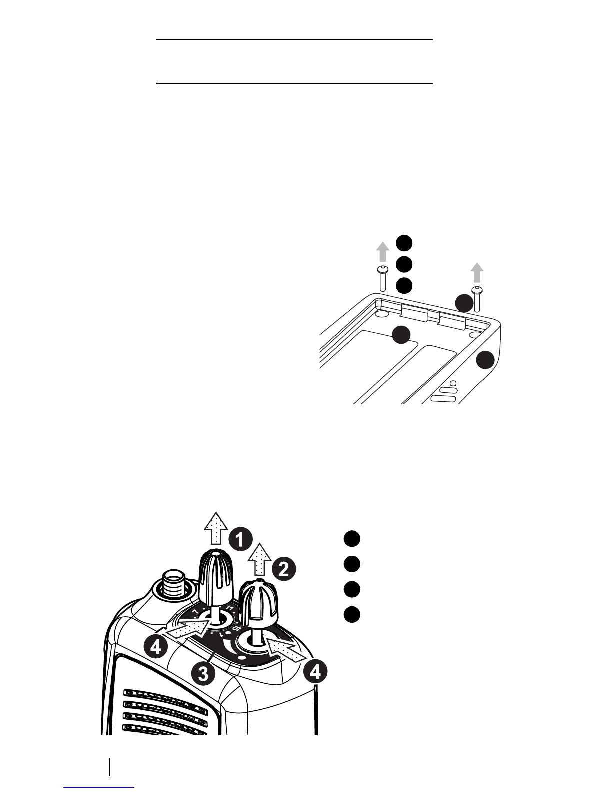
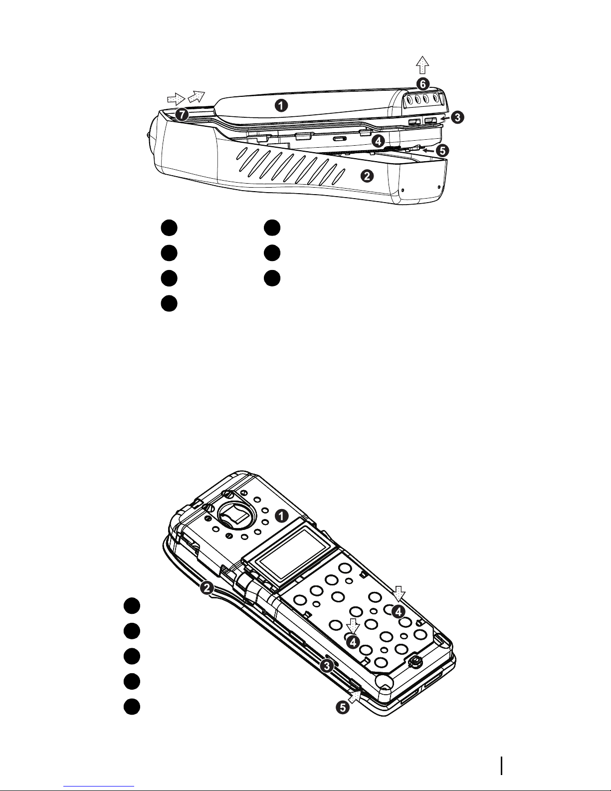
Removing the front panel from the chassis ........................................................... D-4
Removing the shield from the chassis ................................................................... D-5
Removing the PCB from the chassis ...................................................................... D-6
Removing the rear panel ....................................................................................... D-7
Replacing key mechanical and ancillary devices
Replacing key mechanical and ancillary devicesReplacing key mechanical and ancillary devices
Replacing key mechanical and ancillary devices
............................................
........................................................................................
............................................D-8
D-8D-8
D-8
Replacing the lens (Orca 5020, Orca 5035 and Orca 5040) ...................................D-8
Replacing the PTT keypad ..................................................................................... D-8
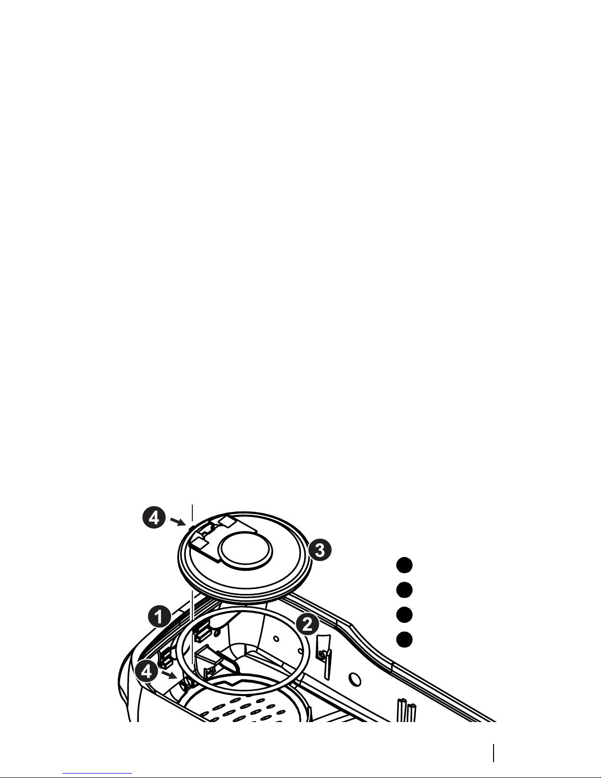
Replacing the speaker ............................................................................................ D-9
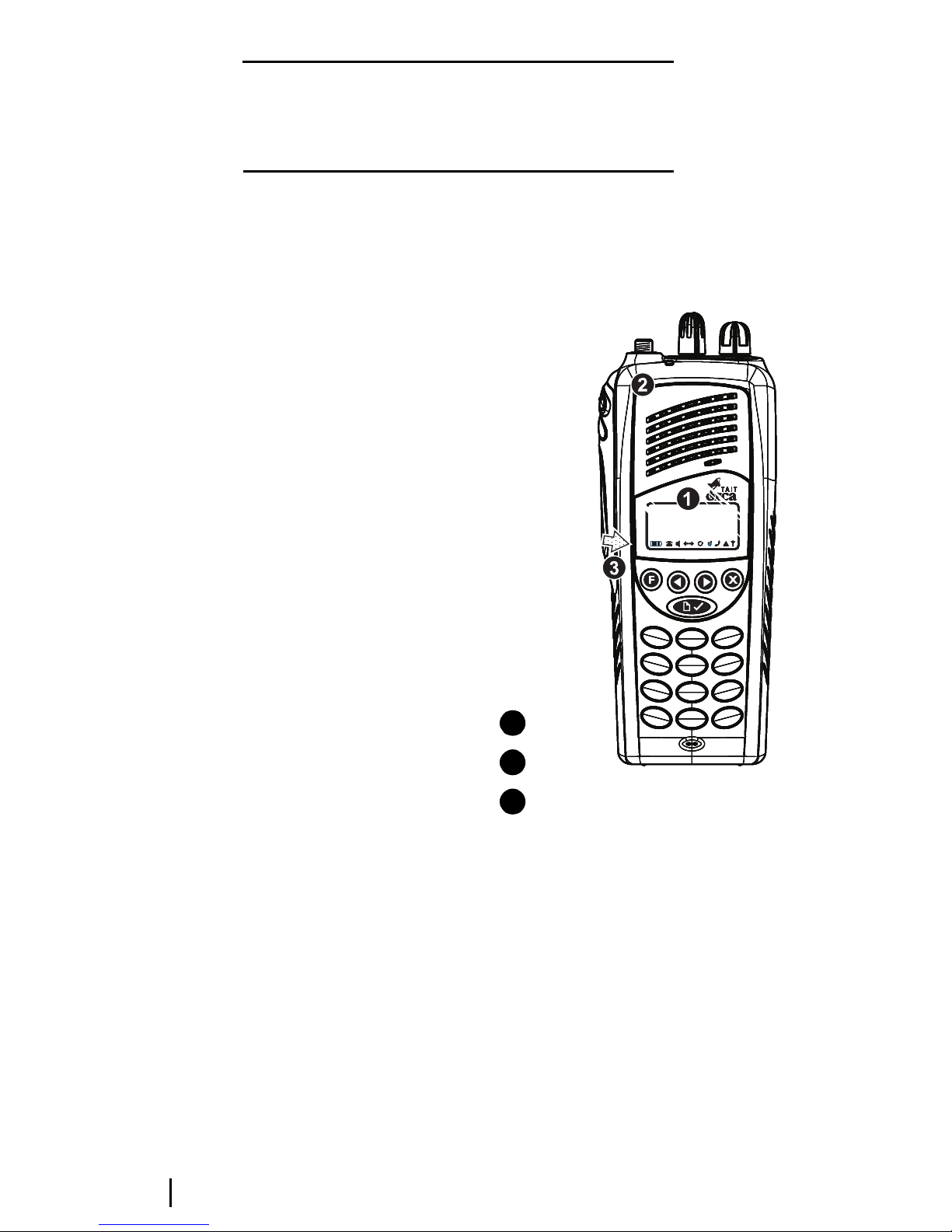
Replacing the LCD display (Orca 5020, Orca 5035 and Orca 5040) ...................... D-9
Replacing the shield, user interface PCB assembly and polyester dome
(Orca 5020, Orca 5035 and Orca 5040) ...............................................................D-12
Replacing the antenna connector, channel selector switch and volume control switch........D-12
Replacing the microphone .................................................................................. D-12
Replacing the battery and speaker contacts ........................................................D-12
Replacing the tact switch ..................................................................................... D-12
Reassembling the radio
Reassembling the radioReassembling the radio
Reassembling the radio
................................................................................
................................................................................................................................................................
................................................................................D-13
D-13D-13
D-13
Rear panel reassembly and replacing the auxiliary flexible PCB .........................D-13
Fitting the PCB to the chassis and replacing the RF out assembly ....................... D-14

D - 2 09/01 IPN: M5000-00-102
Fitting the shield to the chassis ............................................................................D-14
Fitting the front panel to the chassis ....................................................................D-15
Spares kits
Spares kitsSpares kits
Spares kits
...................................................................................................
......................................................................................................................................................................................................
................................................................................................... D-16
D-16D-16
D-16
Orca 5010/5030 spares kit (TOPA-SP-401) ........................................................ D-17
Orca 5035 spares kit (TOPA-SP-402) .................................................................. D-18
Orca 5020/5040 spares kit (TOPA-SP-403) ........................................................ D-19
Orca 5010/5030 Re-skinning kit (TOPA-SP-404) ............................................... D-20
Orca 5035 Re-skinning kit (TOPA-SP-405) ......................................................... D-20
Orca 5020/5040 Re-skinning kit (TOPA-SP-406) ............................................... D-20
Orca 5020/5035/5040 User Interface PCB and Shield (TOPA-SP-407) .............. D-20

09/01 IPN: M5000-00-102 Servicing the radio D - 3
Servicing the radio
The manufacturing process does not allow
direct servicing access to components on the
main PCB. Service repairs of Tait Orca 5000
handportables are therefore limited to key
mechanical and ancillary devices associated
with the main PCB. These include:
■front panel assembly;
■lens (Orca 5020, Orca 5035 and Orca
5040);
■PTT keypad;
■speaker;
■keypad (Orca 5020, Orca 5035 and Orca
5040);
■LCD display (Orca 5020, Orca 5035 and
Orca 5040);
■shield, complete with user interface PCB
assembly and polyester dome (Orca 5020,
Orca 5035 and Orca 5040);
■main PCB assembly;
■antenna connector;
■channel selector switch;
■volume control switch;
■microphone;
■speaker contacts;
■battery contacts;
■PTT tact switch;
■RF out assembly; and
■auxiliary flexible PCB.
A list of spares kits available for servicing Tait
Orca 5000 handportables is shown in Table
D-1 on page D-16. These spares can be ordered
from your local Tait dealer.
Screw head types
Most of the screws in Tait Orca 5000
handportables are Torx head screws, and so a
Torx T6 driver bit is supplied as part of the
service kit. When removing screws be sure to
use the correct driver.
Torx head 1.8*5 mm screws should be
removed using the supplied Torx T6 driver.
When replacing these screws, set the driver to
2 inch pounds.

D - 4 Disassembling the radio 09/01 IPN: M5000-00-102
Disassembling the radio
Removing the front panel from the
chassis
Unscrew the antenna and detachthe batterypack.
The channel selector and on/off/volume
control knobs need to removed before separat-
ing the front panel and the chassis.
To remove the knobs, insert a side cutter at the
base of each knob, flat side down (Figure D-2),
making sure not to damage the knob label and
the switch shaft. Squeeze lightly; the knobs
should pop off. Discard the knobs.
Some earlier Tait Orca 5000 handportables
have the knobs glued on. If so, the knob’s
metal insert will remain on the switch shaft.
Remove the insert using a sharp scalpel blade.
Remove the two chassis screws at the base of
the radio (Figure D-1), then reattach the
battery and hold the base of the radio in one
hand. With the other hand, pull the chassis
from the front panel using the base of the
battery as leverage (Figure D-3).
At this point you can replace the following:
■the front panel assembly;
■the PTT keypad (PTT key and function keys);
■the speaker;
■the lens;
■the keypad; and
■the volume plate and volume keypad.
Figure D-1: Removing the chassis screws
Note that you should not attempt to remove
the PTT keypad before removing the front
panel from the chassis. See “Replacing the PTT
keypad” on page D-8 for more information.
Figure D-2: Removing the knobs
1
3
2
chassis
front panel
chassis screws
1
2
3
channel selector
on/off/volume control
knob label
insert side cutters here
1
2
3
4

09/01 IPN: M5000-00-102 Disassembling the radio D - 5
Figure D-3: Removing the front panel from the chassis, using the battery as leverage
Removing the shield sub-assembly
from the chassis
To remove the shield sub-assembly, place the
radio’s internal assembly on a flat surface with
the shield side facing up toward you. Press
lightly down on the shield sub-assembly above
the slot clip detail (shown in Figure D-4),
which will slightly bow the shield away from
the chassis.
Maintain pressure and insert a flat bladed
screwdriver (approximately 4 mm) in the gap
between the shield and the chassis. Twist the
screwdriver and the shield should rise up over
the clip.
Figure D-4: Removing the shield sub-assembly from
the chassis
battery pack
front panel
chassis
shield
1
2
3
4
microphone grommet protruding from the shield
grip battery here, gently pull away from the front panel
pull radio out and away from the front panel at this point
5
6
7
shield
chassis
slot clip detail
apply pressure here
insert screw driver here and twist
1
2
3
4
5

D - 6 Disassembling the radio 09/01 IPN: M5000-00-102
Repeat this on the other side. Remove the
microphone grommet by pulling upward
(Figure D-5).
You can now see the bottom surface of the
PCB. The basic layout of the PCB is shown in
Figures D-8 and D-9. Refer to these diagrams
for the placement of parts.
Note that on Orca 5020, Orca 5035 and Orca
5040 radios, the user interface loom must be
detached from the main PCB before the shield
can be separated from the main PCB and
chassis.
At this point you can replace:
■the LCD display (Orca 5020, Orca 5035
and Orca 5040); and
■the shield, complete with user interface
PCB assembly and polyester dome (Orca
5020, Orca 5035 and Orca 5040).
Removing the PCB from the
chassis
Remove the knob seal, which covers the anten-
na connector, channel selector switch and
volume control switch.
Remove the screw through the PA shield.
Remove the three nuts for the antenna connec-
tor and knobs using the supplied 8 mm long
reach socket driver, then remove the three
ribbed lock washers. Gently lift the PCB up to
the angle shown in Figure D-5, then pull it
away from the chassis.
At this point you can replace:
■the main PCB assembly;
■the antenna connector;
■the channel selector switch;
■the volume control switch;
■the microphone;
■the speaker contacts;
■the battery contacts;
■the PTT tact switch; and
■the RF out assembly.
Figure D-5: Removing the PCB from the chassis
microphone grommet
PCB
chassis
1
2
3

09/01 IPN: M5000-00-102 Disassembling the radio D - 7
Removing the rear panel
Follow the disassembly instructions and disas-
semble the radio to the PCB level. Refer to
Figure D-10 for the details of the rear panel
assembly.
Insert a small flat bladed screw driver under
the auxiliary dummy rear cover and apply
pressure to push the dummy rear cover lugs
free of the holes in the rear panel. To remove
the rear panel, either:
■slide the cover forward by pushing at the
base with your thumbs; or
■insert a small flat-bladed screwdriver just
under the notch in the base and twist.
Remove the rear panel seal. Note that the RF
contact pin normally remains in the rear panel
seal. Make sure that this is not lost during
disassembly.
Using a calibration pin, lift the auxiliary flexi-
ble PCB contact area from the lower lefthand
corner. Remove the flexible PCB with the seal
from the chassis; they should come out as a
unit.
You can now replace the auxiliary flexible PCB.

D - 8 Replacing key mechanical and ancillary devices 09/01 IPN: M5000-00-102
Replacing key mechanical
and ancillary devices
This section describes the replacement of key
mechanical and ancillary devices associated
with the main PCB. These include:
■lens (Orca 5020, Orca 5035 and Orca
5040);
■PTT keypad;
■speaker;
■LCD display (Orca 5020, Orca 5035 and
Orca 5040);
■shield, complete with user interface PCB
assembly and polyester dome;
■antenna connector;
■channel selector switch;
■volume control switch;
■microphone;
■speaker contacts;
■battery contacts; and
■PTT tact switch.
Note that instructions for replacing the RF out
assembly and the auxiliary flexible PCB are
included as part of the reassembly instructions.
Refer to Figures D-8 and D-9 for the placement
of parts. Once the required devices have been
replaced, refer to the reassembly instructions
on pages D-13 to D-15.
Replacing the lens (Orca 5020,
Orca 5035 and Orca 5040)
You must disassemble the radio before gently
prising the lens away from the front panel of
the radio. Remove any adhesive remaining on
the front panel.
Peel the paper from the back of the new lens,
and place the lens in position on the front
panel.
Press firmly into position, then remove the
piece of clear plastic from the front of the lens.
Figure D-6: Replacing the lens
Replacing the PTT keypad
Following the disassembly instructions,
remove the front panel from the chassis.
To remove the PTT retaining plate, from the
inside of the front panel, gently push the
central latch that holds the retaining plate in
place. Be careful not to lose the two pins that
act as actuators for the function keys.
To replace the PTT retaining plate, insert the
bottom tab into the hole at the bottom of the
PTT recess. Bend the PTT retaining plate very
lens
front panel
gently prise the lens away from the front panel
1
2
3

09/01 IPN: M5000-00-102 Replacing key mechanical and ancillary devices D - 9
slightly so that the top tab slots easily into the
hole at the top of the PTT recess. Be sure not to
split or otherwise damage it.
Replacing the speaker
Following the disassembly instructions,
remove the front panel from the chassis. The
speakers sits in the inside of the front panel
(see Figure D-7).
Using a scalpeland a flat screw driver, carefully
remove the speaker from the front panel.
Clean with alcohol any remaining adhesive
from the speaker seating. Replace the adhesive
ring and secure a new speaker in place. Be sure
to align the tabs.
Figure D-7: Mounting the speaker in the front panel
Replacing the LCD display (Orca
5020, Orca 5035 and Orca 5040)
Following the disassembly instructions, remove
the shield from the front panel and unplug the
user interface loom from the main PCB.
Unplug the LCD display loom from the user
interface PCB, remove the LCD display from
the shield and discard the LCD display.
Position the new LCD display on the shield,
pass the LCD loom through the gap in the
shield and plug into the connector on the user
interface PCB. Push down the two connector
lugs to secure the loom.
Plug the user interface PCB loom onto the
connectoron the main PCB and push down the
connector lugs to secure.
Refit the shield onto the chassis (refer to page
D-14 for detailed instructions).
Place the LCD holder over the LCD, fitting the
LCD holder locating blocks into the holes in
the shield.
Refit the front panel to the chassis (refer to
page D-15 for detailed instructions).
front panel
adhesive
speaker
alignment tabs
1
2
3
4

D - 10 Replacing key mechanical and ancillary devices 09/01 IPN: M5000-00-102
Figure D-8: Bottom surface of the PCB, which is visible when the shield has been removed from the chassis
antenna connector
channel selector switch
on/off/volume control switch
antenna connector pin placement
(5 pins)
speaker contact pin placement
channel selector pin placement
(6 pins)
on/off/volume control pin
placement (5 pins)
PTT tact switch
PA can
PA screw
microphone placement
microphone grommet placement
user interface loom connector
1
2
3
4
5
6
7
8
9
10
11
12
13

09/01 IPN: M5000-00-102 Replacing key mechanical and ancillary devices D - 11
Figure D-9: Top surface of PCB, which is visible only when the PCB has been removed from the chassis
123
4
5
6
7
8
9
antenna connector
channel selector switch
on/off/volume control switch
RF assembly placement
auxiliary flex socket
PTT tact pin placement (4 pins)
battery contact placement
battery contact seal placement
microphone pin placement (2 pins)
1
2
3
4
5
6
7
8
9

D - 12 Replacing key mechanical and ancillary devices 09/01 IPN: M5000-00-102
Replacing the shield, user interface
PCB assembly and polyester dome
(Orca 5020, Orca 5035 and Orca
5040)
On Orca 5020, Orca 5035 and Orca 5040 radios
the shield, user interface PCB and polyester
dome are replaced as one complete assembly.
Following the disassembly instructions, remove
the shield from the front panel and unplug the
user interface loom from the user interface
PCB.
Remove the LCD display assembly from the
discarded shield, and fit to the replacement
shield according to the instructions on page
D-9.
Plug the user interface loom into the connector
on the new user interface PCB, and reassemble
the shield onto the chassis according to the
instructions on page D-14.
Replacing the antenna connector,
channel selector switch and volume
control switch
Following the disassembly instructions, disas-
semble the radio to the PCB level. Remove the
PCB from the chassis.
If any of the antenna connector, channel selec-
tor switch or volume control switch need to be
replaced, remove them using a vacuum-
operated solder station. Replace them accord-
ing to the reassembly instructions on pages
D-13 to D-16.
Replacing the microphone
Following the disassembly instructions, disas-
semble the radio to the PCB level. Remove the
PCB from the chassis.
Use a desoldering station to remove the micro-
phone. Discard the microphone.
When replacing the microphone, make sure it
is aligned with the marks on the PCB, since it is
polarised. Refer to Figures D-8 and D-9 for the
placement of the microphone.
The microphone should not hang over the
edge of the PCB. Solder it in place using a light-
tip soldering iron (e.g. Weller PTR7 tip).
Replacing the battery and speaker
contacts
Following the disassembly instructions, disas-
semble the radio to the PCB level. Remove the
PCB from the chassis.
When replacing one of the battery or speaker
contacts, replace the other contact, even if only
one is faulty. If available, use solder paste to
replace the contacts.
Note that the contacts are heat-sensitive and
will fail if they are overheated.Low tempera-
ture solder must be used and the contacts must
not be heated above 260°C.
Remove the contact with a soldering iron and
discard. Refer to Figures D-7 and D-8 for the
placement of the battery and speaker contacts.
Solder the replacement contact in place using a
heavy-tip soldering iron (e.g. Weller 2PTCC8
tip). Hold onto the contact with a pair of pliers
and apply large amounts of solder to the PCB,
rather than to the contact, to avoid damaging
the contact.
Replacing the tact switch
Following the disassembly instructions, disas-
semble the radio to the PCB level. Remove the
PCB from the chassis.
Remove the PTT tact switch using a desolder-
ing station or solderwick. Note that there is a
lot of solder on both sides of the board, so be
sure to remove it all.
Refer to Figures D-8 and D-9 for the placement
of the PTT tact switch.
Place the new PTT on the board andsolder it in
place using a heavy-tip soldering iron (e.g.
Weller 2PTCC8 tip).

09/01 IPN: M5000-00-102 Reassembling the radio D - 13
Reassembling the radio
This section describes the reassembly of the
radio once the required units have been
serviced. Additional instructions for replacing
the following mechanical and ancillary devices
are also included:
■auxiliary flexible PCB;
■RF out assembly;
■volume plate and volume keypad;
■antenna connector;
■channel selector switch; and
■volume control switch.
Rear panel reassembly and
replacing the auxiliary flexible PCB
Follow the instructions on page D-7 to access
the auxiliary flexible PCB, and replace. Push
the flexible PCB with seal firmly into the
chassis, aligning the notch in the seal with the
locating pin on the chassis (see Figure D-10).
The rubber must sit flush with the back of the
chassis or the rear panel will not sit properly
and the battery will not fit correctly.
Fold the flexible PCB over and fit the contact
area on the chassis; it should fit snugly in place.
Replace the rear panel seal by tucking the two
tags at the top of the seal under the lip on the
chassis and folding it over the flexible PCB.
Check that the RF contact pin is positioned
correctly in the rear panel seal, and that the
seal is flush with the chassis.
Slide the rear panel on from the top of the
radio (Figure D-10). Force it into place by
pressing the top edge of the cover against the
edge of a table; it will clip home. Make sure the
gap between the cover and the chassis is as
small as possible. Refit the auxiliary dummy
cover by pushing the lugs into the holes on the
rear panel. Replace the chassis plug seal,
pushing it onto the chassis boss.
Figure D-10: Rear panel assembly
auxiliary flexible PCB
auxiliary flex seal
end of auxiliary flex connector protruding
through the seal
make sure the seal and auxiliary flex
are firmly seated in the chassis here
rear panel seal
chassis
replace rear panel
RF contact pin
chassis plug seal
1
2
3
4
5
6
7
8
9

D - 14 Reassembling the radio 09/01 IPN: M5000-00-102
Fitting the PCB to the chassis and
replacing the RF out assembly
Put the battery contact seal over the battery
contacts rather than into the chassis. If you put
the seal on the chassis, the contacts will squash
the seal.
Fit the replacement RF out assembly as shown
in Figure D-11.
If you have removed the antenna connector or
either of the switches, fit them on the PCB
(refer to Figures D-8 and D-9), but do not yet
solder them in place. Align them with the holes
in the chassis, and as you lower the PCB onto
the chassis, make sure the accessory flex
protruding from the chassis fitsinto the socket
on the PCB. Lower the PCB onto the chassis,
making sure it is firmly seated.
Fit the PA screw loosely in place. Align the
switches so they are centred, referring to
Figures D-8 and D-9 for placement.
Figure D-12 shows the reassembly of the
antenna and switches. Replace the washers,
making sure the cone faces up. The nuts for the
two switches are black.
Replace the nuts, making sure they are thread-
ed correctly before using an 8 mm long reach
socket driver set to 10 inch pounds. Then tight-
en the PA screw to 2 inch pounds.
Using a heavy-tip soldering iron (e.g. Weller
2PTCC8 tip), solder the antenna connector
and two switches in place, if required, taking
care not to damage the surrounding compo-
nents.
Replace the knob seal over the antenna
connector and the two switches (see Figure
D-12).
Fitting the shield to the chassis
Replace the microphone grommet over the
microphone.
Replace the shield from the top of the radio,
ensuring that the two pins on the chassis go
into the two holes at the top of the shield.
Should the main seal need replacing, place the
new seal so that the notch at the top of the
chassis (behind the channel selector switch)
matches that on the seal and the profile match-
es the chassis.
Run your finger around the seal to ensure that
it fits properly into the seal retaining well.
Figure D-11: Placing the RF out assembly
2
43
1
RF out assembly
insert here
antenna connector
auxiliary flex socket
1
2
3
4

09/01 IPN: M5000-00-102 Reassembling the radio D - 15
Figure D-12: Assembly of the switches
Fitting the front panel to the
chassis
Place the radio into the front panel top first,
inserting the antenna connector and knob
switches through the holes. Gently ease the
radio into the front panel until the edge of the
chassis is flush with the edge of the front panel,
while making sure that the seal is not pinched;
using the battery as leverage as in radio disas-
sembly maybe helpful. Replace the two chassis
screws at the base of the radio, tightening them
to 2 inch pounds.
Replace the two knobs on the radio with new
knobs, after placing a spot of Loctite™ 680 on
each switch shaft. Make sure there is no gap
between the base of each knob and the knob
label by firmly pressing the top of each knob
against a firm surface. Choose a surface that will
not damage the top of the knob.
8
9
7
45
6
2
1
3
66
8
shield
chassis
antenna connector
channel selector switch
on/off/volume control switch
ribbed lock washer (M6*10*0.7 mm)
SMA connector nut (¼*7.9*3 mm)
channel/volume control nut
(M6*7.9*3 mm)
knob seal
1
2
3
4
5
6
7
8
9

D - 16 Spares kits 09/01 IPN: M5000-00-102
Spares kits
The following table shows a list of spares kits
which are currently available for servicing Tait
Orca 5000 handportables. Spares kits are
designed to service 100 radios, and can be
ordered from your local Tait dealer.
Table D-1: Spares kits
The contents of the Orca 5000 low, mid and
high tier spares kits (TOPA-SP-401, TOPA-SP-
402 and TOPA-SP-403) are shown in Tables
D-2, D-3 and D-4. The contents of the Orca
5000 handportable re-skinning kits are shown
in Tables D-5, D-6 and D-7.
Note that the ‘IPN’ column is the ten digit
‘internal part number’ which uniquely identi-
fies any component used in a Tait product.
The numbers in the ‘Reference’ column are
Figure numbers in which the spares item is
shown, and the number in brackets refers to
the numbered legend within each figure.
Tait Orca 5000 main PCBs are available on an
exchange basis from the Customer Services
Division of Tait Electronics Ltd. When order-
ing, use the following naming convention
TOP-XXXXX-KS.
For example, a replacement main PCB for a
TOP-B2620-T0 is a TOP-B2620-KS.
Product code Description
TOPA-SP-401 Orca 5010/5030 spares kit
TOPA-SP-402 Orca 5035 spares kit
TOPA-SP-403 Orca 5020/5040 spares kit
TOPA-SP-404 Orca 5010/5030 re-skinning kit
TOPA-SP-405 Orca 5035 re-skinning kit
TOPA-SP-406 Orca 5020/5040 re-skinning kit
TOPA-SP-407 Orca 5020/5035/5040 U/I PCB +
shield
TOPA-SP-504 Battery catch x 10
TOPA-SP-506 Orca 5000 series volume knobs x 10
TOPA-SP-507 Orca 5000 series channel knobs x 10

09/01 IPN: M5000-00-102 Spares kits D - 17
Table D-2: Orca 5010/5030 spares kit (TOPA-SP-401)
IPN Description Quantity Reference
040-05500-08 Volume Control Switch 10 D-8 (3), D-9 (3)
219-50029-00 RF out assembly 5D-11 (1)
220-01414-03 Aux Flex Connector PCB 5D-10 (1)
231-00010-45 Channel Selector Switch 10 D-8 (2), D-9 (2)
232-00010-42 Switch PTT (Low Profile) 5D-8 (8), D-9 (6)
240-02156-01 Antenna SMA Connector 10 D-12 (4)
252-00010-77 Speaker 40mm 0.5W 16E FST 5 —
252-00010-56 Microphone 5D-8 (11)
316-85133-00 PTT/Function Key Retaining Plate 10 —
360-02019-00 Microphone Grommet/Seal 10 D-5 (1)
303-11213-00 Handportable Chassis 5D-4 (2), D-5 (3)
303-30072-00 Battery Catch 20 —
308-01057-02 Housing Accessory Dummy Cover 20 —
311-01049-00 Channel Selector Knob 20 D-2 (1)
311-03108-00 PTT/Function Keypad 20 —
316-06765-00 Rear Panel 5D-10 (7)
316-06763-00 Knob Label 5D-2 (3)
365-01673-00 Insert Front Panel Logo Label 1 —
319-01026-00 Main RF Shield 5D-4 (1)
345-00020-09 PA Screw M2x5mm Pan Torx 10 D-8 (10)
345-00020-11 Chassis Screw M2x8mm Pan Torx 10 D-1 (3)
349-00030-00 Speaker Screw 1.8x5mm Torx 10 D-7 (3)
352-00010-52 Channel/volume Control Nut (M6x7.9x3mm) 20 D-12 (9)
352-01053-00 Antenna SMA Connector Nut 10 D-12 (8)
353-00010-42 Ribbed Lock Washer M6x10x0.7mm 30 D-12 (7)
356-01077-00 Battery Contact Probe 10 D-9 (7)
360-01060-00 PTT/Function Key Actuator 40 —
360-00010-39 Chassis Plug Seal 10 D-10 (9)
362-01087-00 Battery Contact Seal 10 D-9 (8)
362-01106-00 Rear Panel Seal 10 D-10 (5)
362--01089-01 Aux Flex Seal 10 D-10 (2)
362-01091-01 Knob Seal 10 D-12 (10)
362-01092-02 Main Seal 20 —
369-01039-00 Adhesive Ring 40mm (speaker) 5D-7 (2)
OPP401 Front Panel Assembly. This comprises the following parts: 1 —
252-00010-77 Speaker 40mm 0.5W 16E FST 1 —
307-01022-00 Speaker cloth 1 —
316-06760-00 Front Panel 1 —
316-06763-00 Knob Label 1D-2 (3)
354-01044-00 Bush M2 Threaded Brass 2 —
369-01039-00 Adhesive Ring 40mm (speaker) 1D-7 (2)

D - 18 Spares kits 09/01 IPN: M5000-00-102
Table D-3: Orca 5035 spares kit (TOPA-SP-402)
IPN Description Quantity Reference
040-05500-08 Volume Control Switch 10 D-8 (3), D-9 (3)
219-50029-00 RF out assembly 5D-11 (1)
220-01414-03 Aux Flex Connector PCB 5D-10 (1)
231-00010-45 Channel Selector Switch 10 D-8 (2), D-9 (2)
232-00010-42 Switch PTT (Low Profile) 5D-8 (8), D-9 (6)
240-02156-01 Antenna SMA Connector 10 D-12 (4)
252-00010-77 Speaker 40mm 0.5W 16E FST 5 —
252-00010-56 Microphone 5D-8 (11)
304-07043-00 LCD Holder 1 —
360-02019-00 Microphone Grommet/Seal 10 D-5 (1)
303-11213-00 Handportable Chassis 5D-4 (2), D-5 (3)
303-30072-00 Battery Catch 20 —
308-01057-02 Housing Accessory Dummy Cover 20 —
311-01049-00 Channel Selector Knob 20 D-2 (1)
311-01050-00 Volume Knob 20 D-2 (2)
311-03108-00 PTT/Function Keypad 20 —
316-06765-00 Rear Panel 5D-10 (7)
316-06763-00 Knob Label 5D-2 (3)
316-85133-00 PTT/Function Key Retaining Plate 10 —
319-01203-00 Main RF Shield 5D-4 (1)
345-00020-09 PA Screw M2x5mm Pan Torx 10 D-8 (10)
345-00020-11 Chassis Screw M2x8mm Pan Torx 10 D-1 (3)
349-00030-00 Speaker Screw 1.8x5mm Torx 10 D-7 (3)
352-00010-52 Channel/volume Control Nut (M6x7.9x3mm) 20 D-12 (9)
352-01053-00 Antenna SMA Connector Nut 10 D-12 (8)
353-00010-42 Ribbed Lock Washer M6x10x0.7mm 30 D-12 (7)
356-01077-00 Battery Contact Probe 10 D-9 (7)
360-01060-00 PTT/Function Key Actuator 40 —
360-00010-39 Chassis Plug Seal 10 D-10 (9)
362-01087-00 Battery Contact Seal 10 D-9 (8)
362-01106-00 Rear Panel Seal 10 D-10 (5)
362--01089-01 Aux Flex Seal 10 D-10 (2)
362-01091-01 Knob Seal 10 D-12 (10)
362-01092-02 Main Seal 20 —
369-01039-00 Adhesive Ring 40mm (speaker) 5D-7 (2)
OPP501 Front Panel Assembly. This comprises the following parts: 1 —
252-00010-77 Speaker 40mm 0.5W 16E FST 1 —
307-01022-00 Speaker cloth 1 —
316-06761-00 Front Panel 1 —
316-06763-00 Knob Label 1D-2 (3)
354-01044-00 Bush M2 Threaded Brass 2 —
369-01039-00 Adhesive Ring 40mm (speaker) 1D-7 (2)
312-10183-00 Lens 1D-6 (1)
008-36671-80 LCD Display 1 —
220-01501-00 User Interface Loom PCB 5 —
311-03110-00 Keypad 5 —
311-04006-00 Polyester Dome 5 —
312-01083-00 Lens 2D-6 (1)
OPF200-B UI PCB SMT Subassembly 1 —
365-00011-38 Yellow static warning label 3 —
399-00010-86 Static Shielding Bag 127x203mm 3 —

09/01 IPN: M5000-00-102 Spares kits D - 19
Table D-4: Orca 5020/5040 spares kit (TOPA-SP-403)
IPN Description Quantity Reference
040-05500-08 Volume Control Switch 10 D-8 (3), D-9 (3)
219-50029-00 RF out assembly 5D-11 (1)
220-01414-03 Aux Flex Connector PCB 5D-10 (1)
231-00010-45 Channel Selector Switch 10 D-8 (2), D-9 (2)
232-00010-42 Switch PTT (Low Profile) 5D-8 (8), D-9 (6)
240-02156-01 Antenna SMA Connector 10 D-12 (4)
252-00010-77 Speaker 40mm 0.5W 16E FST 5 —
252-00010-56 Microphone 5D-8 (11)
304-07043-00 LCD Holder 1 —
316-85133-00 PTT/Function Retaining Plate 10 —
360-02019-00 Microphone Grommet/Seal 10 D-5 (1)
303-11213-00 Handportable Chassis 5D-4 (2), D-5 (3)
303-30072-00 Battery Catch 20 —
308-01057-02 Housing Accessory Dummy Cover 20 —
311-01049-00 Channel Selector Knob 20 D-2 (1)
311-01050-00 Volume Knob 20 D-2 (2)
311-03108-00 PTT/Function Keypad 20 —
316-06765-00 Rear Panel 5D-10 (7)
316-06763-00 Knob Label 5D-2 (3)
319-01203-01 Main RF Shield 5D-4 (1)
345-00020-09 PA Screw M2x5mm Pan Torx 10 D-8 (10)
345-00020-11 Chassis Screw M2x8mm Pan Torx 10 D-1 (3)
349-00030-00 Speaker Screw 1.8x5mm Torx 10 D-7 (3)
352-00010-52 Channel/volume Control Nut (M6x7.9x3mm) 20 D-12 (9)
352-01053-00 Antenna SMA Connector Nut 10 D-12 (8)
353-00010-42 Ribbed Lock Washer M6x10x0.7mm 30 D-12 (7)
356-01077-00 Battery Contact Probe 10 D-9 (7)
360-01060-00 PTT/Function Key Actuator 40 —
360-00010-39 Chassis Plug Seal 10 D-10 (9)
362-01087-00 Battery Contact Seal 10 D-9 (8)
362-01106-00 Rear Panel Seal 10 D-10 (5)
362--01089-01 Aux Flex Seal 10 D-10 (2)
362-01091-01 Knob Seal 10 D-12 (10)
362-01092-02 Main Seal 20 —
369-01039-00 Adhesive Ring 40mm (speaker) 5D-7 (2)
OPP601 Front Panel Assembly. This comprises the following parts: 1 —
252-00010-77 Speaker 40mm 0.5W 16E FST 1 —
307-01022-00 Speaker cloth 1 —
316-06762-00 Front Panel 1 —
316-06763-00 Knob Label 1D-2 (3)
354-01044-00 Bush M2 Threaded Brass 2 —
369-01039-00 Adhesive Ring 40mm (speaker) 1D-7 (2)
312-10183-00 Lens 1D-6 (1)
008-36671-80 LCD Display 1 —
220-01501-00 User Interface Loom PCB 5 —
311-03109-00 Keypad 5 —
311-04005-00 Polyester Dome 5 —
312-01083-00 Lens 2D-6 (1)
OPF200-B UI PCB SMT Subassembly 1 —
365-00011-38 Yellow static warning label 3 —
399-00010-86 Static Shielding Bag 127x203mm 3 —

D - 20 Spares kits 09/01 IPN: M5000-00-102
Table D-5: Orca 5010/5030 Re-skinning kit (TOPA-SP-404)
Table D-6: Orca 5035 Re-skinning kit (TOPA-SP-405)
Table D-7: Orca 5020/5040 Re-skinning kit (TOPA-SP-406)
Table D-8: Orca 5020/5035/5040 User Interface PCB and Shield (TOPA-SP-407)
IPN Description Quantity
311-01049-00 Channel Knob Gr 1
311-01050-00 Volume Knob Gr 1
311-03108-00 PTT/Function Keypad 1
316-06765-00 Rear Panel 1
316-85133-00 PTT/Function keypad retainer plate 1
345-00020-11 Screw M2x8mm SS Pan Torx Patch 2
360-01060-00 Actuator Pressel 2
362-01106-00 Rear Cover Seal 1
362-01091-01 Knob Seal 1
362-01092-02 Main Seal 1
OPP401 PHA Front Panel Assembly 1
IPN Description Quantity
311-01049-00 Channel Knob Gr 1
311-01050-00 Volume Knob Gr 1
311-03108-00 PTT/Function Keypad 1
316-06765-00 Rear Panel 1
316-85133-00 PTT/Function keypad retainer plate 1
345-00020-11 Screw M2x8mm SS Pan Torx Patch 2
360-01060-00 Actuator Pressel 2
362-01106-00 Rear Cover Seal 1
362-01091-01 Knob Seal 1
362-01092-02 Main Seal 1
OPP501 PHA Front Panel Assembly 1
IPN Description Quantity
311-01049-00 Channel Knob Gr 1
311-01050-00 Volume Knob Gr 1
311-03108-00 PTT/Function Keypad 1
316-06765-00 Rear Panel 1
316-85133-00 PTT/Function keypad retainer plate 1
345-00020-11 Screw M2x8mm SS Pan Torx Patch 2
360-01060-00 Actuator Pressel 2
362-01106-00 Rear Cover Seal 1
362-01091-01 Knob Seal 1
362-01092-02 Main Seal 1
OPP601 PHA Front Panel Assembly 1
IPN Description Quantity
OPF200-B UI PCB SMT Subassembly 1
311-04005-00 Ins Poly Dome for 5020/5040 1
319-01026-00 Main Shield RF 1
399-00010-86 Static Shielding Bag 127x203mm 1
008-36671-80 LCD Display 12x2 Lines Flex 1
304-07043-00 LCD Frame Holder 1
220-01501-00 PCB Flexi User Interface 1
Other manuals for Orca 5020
1
This manual suits for next models
2
Table of contents
Other Tait Radio manuals

Tait
Tait TM9100 User manual

Tait
Tait T2000 SERIES II User manual

Tait
Tait TM9100 Series P25 User manual

Tait
Tait TM9400 User manual

Tait
Tait TM9100 User manual

Tait
Tait TM8100 mobiles User manual

Tait
Tait TM9100 User manual

Tait
Tait TM9315 User manual

Tait
Tait TM8100 mobiles User manual

Tait
Tait TM8100 mobiles User manual

Tait
Tait TM8260 Installation guide

Tait
Tait TM9480 User manual

Tait
Tait TM8200 mobiles User manual

Tait
Tait t2040 series ii User manual

Tait
Tait t2020 User manual

Tait
Tait TM8235 User manual

Tait
Tait TM9300 DMR User manual

Tait
Tait T8000 Quick start guide

Tait
Tait TM8100 mobiles User manual

Tait
Tait TM2210 User manual