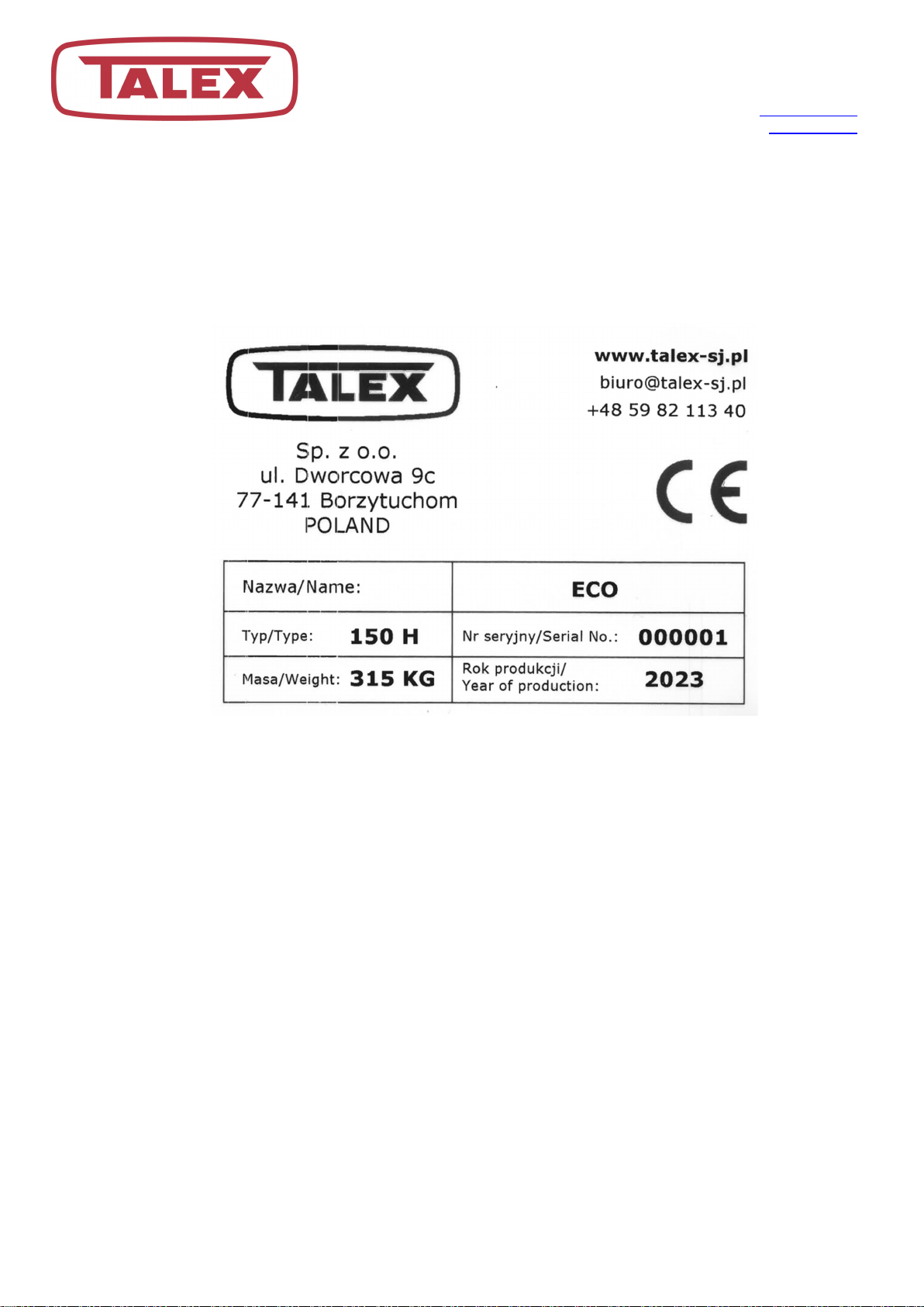
Talex LIGHT FLAIL MOWER ECO 100 User manual

TALEX Sp. z o.o.
ul. Dworcowa 9c
77-141 Borzytuchom
tel.: +48 59 821 13 40
e-mail: [email protected]
www.talex-sj.pl
USER MANUAL
SPARE PARTS CATALOGUE
WARRANTY
LIGHT FLAIL MOWER ECO
100; 135; 135H; 150; 150H;
180; 180H; 200; 200H; 220; 220H
Borzytuchom 2023 - ISSUE 02
TRANSLATION OF THE ORIGINAL MANUAL

TALEX Sp. z o.o.
ul. Dworcowa 9c
77-141 Borzytuchom
tel.: +48 59 821 13 40
e-mail: [email protected]
www.talex-sj.pl
2
CAUTION!
The safety regulations shall be followed while using the machine and this manual shall be read prior to the
machine operation.
The manual is an integral part of the machine equipment!
The manual shall be kept in a safe place and shall be available for user and an operator during the whole
period of the machine operation
If the manual is lost or destroyed, new manual shall be purchased in the machine retail outlet or at the
manufacturer’s office.
If the machine is sold or made available to other user, the manual and the declaration of conformity shall be
attached to the machine.
The manufacturer reserves all rights to this manual.
Copying, processing the manual as a whole or its part with no consent of the manufacturer is forbidden.

TALEX Sp. z o.o.
ul. Dworcowa 9c
77-141 Borzytuchom
tel.: +48 59 821 13 40
e-mail: [email protected]
www.talex-sj.pl
3
TABLE OF CONTENTS
1. Machine identification ..................................................................................................................... 5
2. Introduction ................................................................................................................................... 6
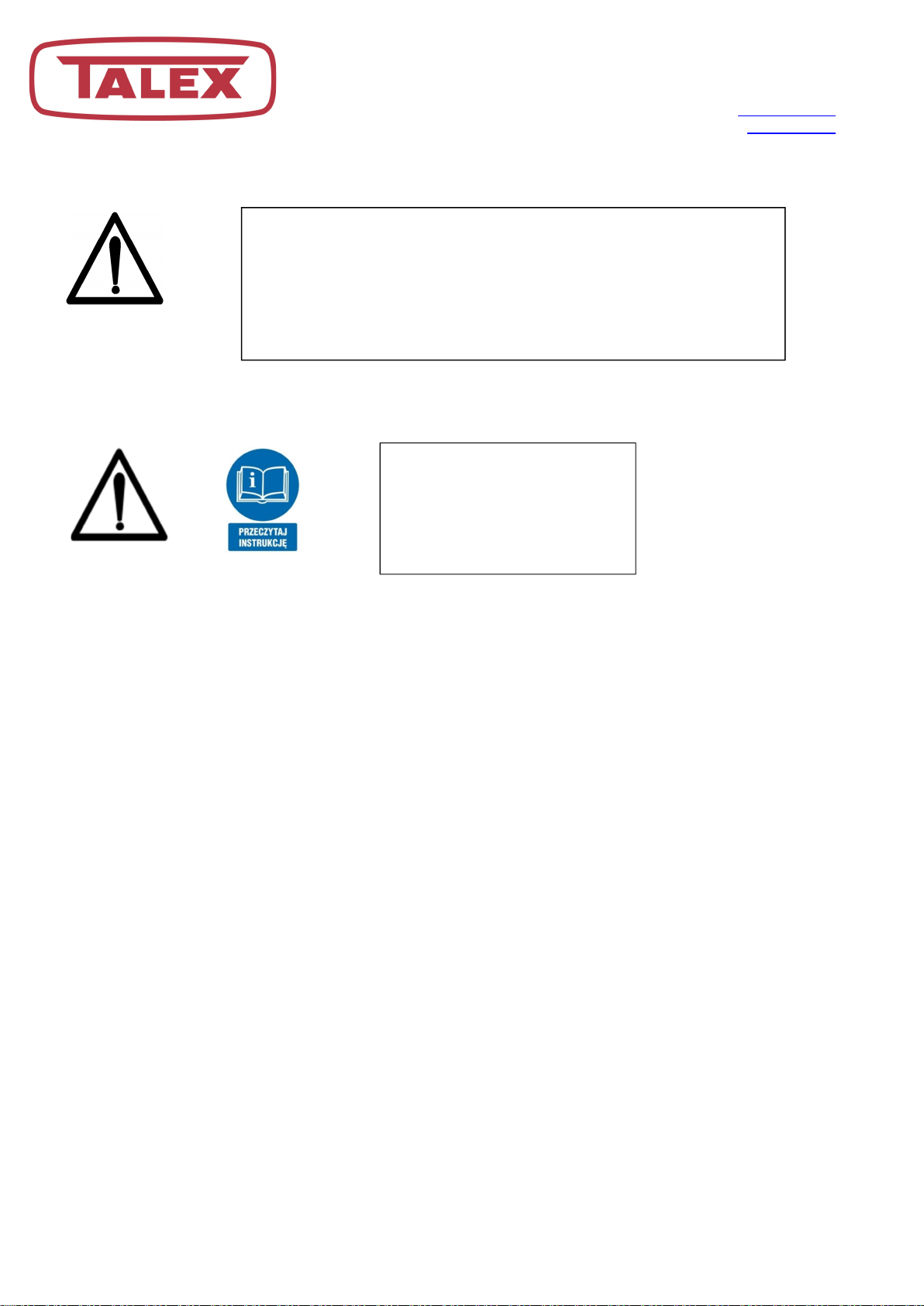
Read the manual ...................................................................................................................... 6
2.1.
Intended use ........................................................................................................................... 6
2.2.
Warranty ................................................................................................................................. 7
2.3.
3. Health and safety rules .................................................................................................................... 7
General safety rules .................................................................................................................. 7
3.1.
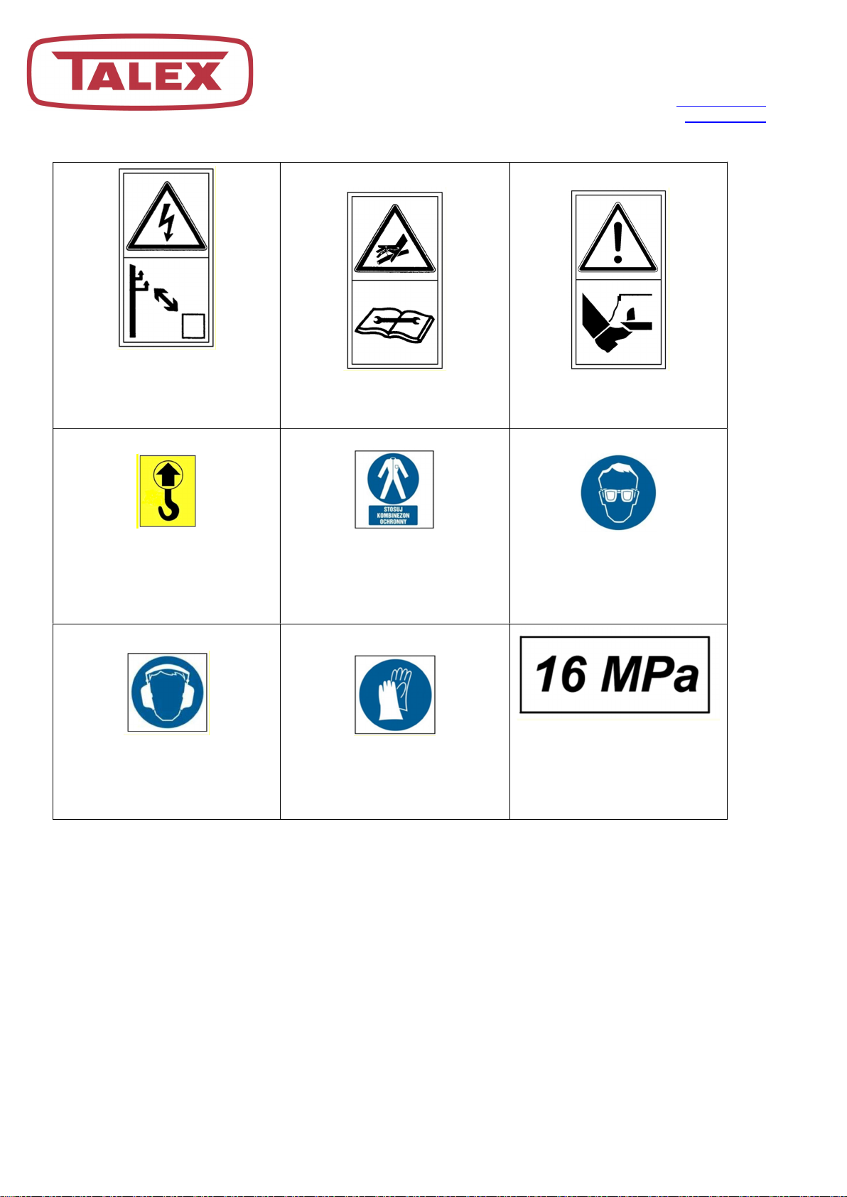
Safety signs on the machine .................................................................................................. 9
3.2.
Threats occurring during the use of the mower .................................................................... 11
3.3.
Working parts of the machine .................................................................................................. 12
3.4.
Machines linked with three point hitch ..................................................................................... 12
3.5.
Machine unlinked from the tractor ........................................................................................... 12
3.6.
Work with the PTO shaft ......................................................................................................... 12
3.7.
Service .................................................................................................................................. 13
3.8.
Technical specification ............................................................................................................ 14
3.9.
Construction and operation ................................................................................................. 15
3.10.
4. Usage ........................................................................................................................................... 16
Linking the machine with the tractor, setting and adjusting the height. ........................................ 16
4.1.
Work .................................................................................................................................... 17
4.2.
5. Recommended machine maintenance ............................................................................................. 18
Greasing ................................................................................................................................ 18
5.1.
V-belts tensioning .................................................................................................................. 19
5.2.
Replacing the flail hammers ................................................................................................. 20
5.3.
6. Technical inspections, storage and utilization ................................................................................... 21
Storage ................................................................................................................................. 22
6.1.
Disassembly and utilization ..................................................................................................... 22
6.2.
7. Spare parts catalogue ................................................................................................................. 23
General machine construction ............................................................................................. 24
7.1.
Working shaft ....................................................................................................................... 26
7.2.
Contour following roller ECO 100, 135, 150 ......................................................................... 27
7.3.
Contour following roller ECO 180, 200, 220 ......................................................................... 28
7.4.
Rear curtain ......................................................................................................................... 29
7.5.
Skids .................................................................................................................................... 31
7.6.
V-belt gearbox cover ECO 100/135/150 .............................................................................. 32
7.7.

TALEX Sp. z o.o.
ul. Dworcowa 9c
77-141 Borzytuchom
tel.: +48 59 821 13 40
e-mail: [email protected]
www.talex-sj.pl
4
V-belt gearbox cover ECO 180/200/220 .............................................................................. 33
7.8.
Belt tensioner ...................................................................................................................... 34
7.9.
Fixed headstock ............................................................................................................... 35
7.10.
Hydraulic headstock......................................................................................................... 36
7.11.
Drive train ........................................................................................................................ 38
7.12.
Stone curtain ................................................................................................................... 41
7.13.
Bumper ............................................................................................................................ 42
7.14.
Body with end cap ........................................................................................................... 43
7.15.
8. Warranty..................................................................................................................................... 44
9. Declaration of conformity CE ...................................................................................................... 46
TABLE OF FIGURES.
Fig 1. ECO shredder dimensions ....................................................................................................... 15
Fig 2. Shredder drive diagram ........................................................................................................... 16
Fig 3. Linking the shredder ................................................................................................................ 17
Fig 4. Oil change holes ...................................................................................................................... 18
Fig 5. Greasing diagram .................................................................................................................... 19
Fig 6. Belt tensioning scheme ............................................................................................................ 20
Fig 7. Flail hammer assembly ............................................................................................................ 20
Fig 8. General machine construction ................................................................................................. 24
Fig 9. General machine construction ................................................................................................ 24
Fig 10. Working shaft components .................................................................................................... 26
Fig 11. Complete contour following roller ECO 100, 135, 150 ........................................................... 27
Fig. 12. Complete contour following roller ECO 180, 200, 220 ........................................................... 28
Fig 13. Complete rear curtain....................................................................................................... 29
Fig 14. Complete skid ........................................................................................................................ 31
Fig 15. Complete v-belt gearbox cover ECO 100/135/150 ................................................................. 32
Fig 16. Complete v-belt gearbox cover ECO 180/200/220 ................................................................. 33
Fig 17. Belt tensioner ......................................................................................................................... 34
Fig 18. Fixed headstock - set ............................................................................................................. 35
Fig 19. Hydraulic headstock - set....................................................................................................... 36
Fig 20. Components of the drive train ................................................................................................ 38
Fig 21. Stone curtain ......................................................................................................................... 41
Fig 22. Bumper components .............................................................................................................. 42
Fig 23. Body with end cap ................................................................................................................. 43

TALEX Sp. z o.o.
ul. Dworcowa 9c
77-141 Borzytuchom
tel.: +48 59 821 13 40
e-mail: [email protected]
www.talex-sj.pl
5
1. Machine identification
All the information needed for identification is located on the nameplate, which is attached to the body of
the machine. It contains such information as the name and address of the manufacturer, year of production
, factory number, weight of the machine.
Fig 1: Nameplate
In case of uncertainty, the dealer or manufacturer should provide any information about the machine and
clarification of the operating instructions.
Manufacturer’s adress:
TALEX Spółka z ograniczoną odpowiedzialnością
ul. Dworcowa 9c
77-141 Borzytuchom
POLAND
Tel.: +48 59 821 13 40
www.talex-sj.pl
e-mail:[email protected]

TALEX Sp. z o.o.
ul. Dworcowa 9c
77-141 Borzytuchom
tel.: +48 59 821 13 40
e-mail: [email protected]
www.talex-sj.pl
6
2. Introduction
Read the manual
2.1.
The user manual is provided with the machine. Please read it carefully before starting any work with the
machine.
This manual provides the user with information on the operation, use and maintenance of the machine. It
contains operational characteristics, requirements for safe and correct operation with the machine,
allowing the best use of the machine with maximum service life and reliability. A careful reading of the
operating instructions will help to avoid accidents and allow for long and trouble-free service.
Intended use
2.2.
The machine is designed for normal, typical agricultural use, i.e. for mowing and shredding of low-stemmed
plants (bushes, plant stems, etc.).
The use of the shredder for other purposes shall be considered as misuse. This excludes the manufacturer's
responsibility for any damage resulting from such use.
The machine may only be operated by trained operators who have read the operating instructions
and have been authorised to drive a vehicle with a shredder.
The shredder shall be used for its intended use and properly maintained and repaired.
Follow the safety regulations specified in this manual, general health and safety rules, road traffic
rules.
Follow the occupational health and safety rules when operating and maintaining the machine.
Unauthorised modifications to the machine exclude the manufacturer's responsibility for any
damage resulting therefrom.
CAUTION!
This symbol indicates danger.
This warning symbol indicates important information about the dangers.
You are requested to read the information carefully,
Follow the recommendations
CAUTION!
Read the operating instructions
before use

TALEX Sp. z o.o.
ul. Dworcowa 9c
77-141 Borzytuchom
tel.: +48 59 821 13 40
e-mail: [email protected]
www.talex-sj.pl
7
Warranty
2.3.
Warranty conditions are stated in the warranty card. It is the responsibility of the machine operator to
thoroughly familiarise himself with this operating manual. Failing to follow the rules of proper operation
will lead to a reduction in the efficiency of the shredder, its failure and the loss of warranty rights. Warranty
entitlements will be lost in particular in the following cases:
1. Any mechanical damage caused by operation that does not comply with the operating instructions,
particularly mowing when driving backwards.
2. Performing repairs by workshops other than the dealer's service centre, the factory service centre or
the service centre indicated by the manufacturer.
3. Use of other than original spare parts for repairs.
4. Any unauthorised modifications to the shredder build.
3. Health and safety rules
Most of the accidents that occur during work, handling or transport are down to a non-compliance with
elementary safety rules. It is therefore important that anyone working with the machine follows the
following basic safety rules as closely as possible:
General safety rules
3.1.
1. Observe the general rules of health and safety in addition to the instructions in this manual!
2. Comply with the indications of warning signs and symbols on the machine. Compliance with them
protects the operator safety!
3. It is forbidden to use the machine without the necessary safety guards, damaged guards must be
replaced by original spare parts.
4. Do not start shredder operation until the tractor's PTO nominal speed has been reached. Do not
exceed 540 rpm.
5. It is forbidden to do any work on the machine while the moving parts are rotating, it is mandatory to
wait until they have stopped. Never wear loose clothing which can be snagged by rotating parts.
6. Never leave the shredder running when not in control
7. Ensure that no persons or animals are in the danger zone before or during the mower operation.
Operating the shredder in the presence of bystanders within a distance of less than 50 m is
prohibited!
8. It is forbidden to climb onto the machine.
9. Fields and meadows must be cleared of stones and hard objects before work- larger stones must be
removed.
10. It is forbidden to operate the mower while driving backwards.
11. It is forbidden to step between the tractor and the machine until the shredder has been secured
against rolling before the tractor parking brake has been locked or by placing chocks under the
wheels..

TALEX Sp. z o.o.
ul. Dworcowa 9c
77-141 Borzytuchom
tel.: +48 59 821 13 40
e-mail: [email protected]
www.talex-sj.pl
8
12. The control of the tractor's hydraulic linkage lever should be carried out only from the driver's seat
position.
13. It is not allowed to operate the lifting and lowering lever from outside the vehicle.
14. It is forbidden to raise the machine on the tractor's hydraulic linkage when the drive is switched on
and the working shaft is rotating.
15. Be particularly careful when working on slopes and hillsides.
16. Do not use dangling, unbuttoned pieces of clothing when working, fitting, adjusting, dismantling. Keep
them away from structural components that can snag them.

TALEX Sp. z o.o.
ul. Dworcowa 9c
77-141 Borzytuchom
tel.: +48 59 821 13 40
e-mail: [email protected]
www.talex-sj.pl
9
Safety signs on the machine
3.2.
Prior to using the machine,
read
the User Manual
Switch off the engine and
remove the key before
carrying out maintenance or
repair work
Keep a safe distance from
the machine. Do not allow
bystanders to be within less
than 50m away
Warning, belt transmission.
Use extreme caution.
Drawing-in of hand
and arm.
Warning, possibility of being
drawn-in by the machine
Keep a safe distance from
the machine.
Crushing of toes or foot –
Force applied from above
Do not ride on platforms or
ladders
Do not stand near the lift
strands when
controlling the lift
Do not open or remove
safety guards
when the engine is running

TALEX Sp. z o.o.
ul. Dworcowa 9c
77-141 Borzytuchom
tel.: +48 59 821 13 40
e-mail: [email protected]
www.talex-sj.pl
10
Keep a safe distance from
power lines
Avoid exposure to liquids
flowing under pressure.
Warning : cutting knives.
Keep away from the working
mower
Lifting points on the mower
during handling
Use protective
coverall
Wear eye protection
Wear ear protectors
Use safety gloves
Warning message about
pressure in
the hydraulic system

TALEX Sp. z o.o.
ul. Dworcowa 9c
77-141 Borzytuchom
tel.: +48 59 821 13 40
e-mail: [email protected]
www.talex-sj.pl
11
Threats occurring during the use of the mower
3.3.
No. Threat Source of threat (reason) Measures to protect against threats
1 Overload of the
motion system
(physical load)
Working in a standing, tilted-
forced position, walking,
moving
Reading the instruction manual, on-the-job training
including the weight carrying standards while
performing manual transport works, proper techniques
of weights carrying, other person assistance, devices
facilitating the transport i.e. lifting jack, hoisting winch
2 Fall at the same
level (falter, slipping
etc.)
Bumpy surface, disorder –
laying and standing items,
items on the passageways,
slippery surfaces
Proper working shoes, plane surface, staying alerted,
keeping it tidy, reading the instruction manual
3
Hitting fixed parts of
the machine
Machine and its surroundings Proper position of the machine, safe space for moving,
proper organization of work, staying alerted, reading
the instruction manual
4
Being hit by the
mowed material
Granulated plants, accidental
parts of turf, stones thrown
by the machine
Observing due attention, designating the danger zone,
prohibiting movement while the machine is running,
removing stones, prohibiting work in stony areas, use of
personal protective equipment - protective helmet,
glasses, familiarization with the operator's manual
5 Sharp dangerous
edges
Projecting structural elements
of the machine, use of hand
tools
Personal protective equipment - protective gloves,
working clothes fastened, special attention
6 Belt gearboxes Moving gear wheels and
belts, rotating PTO shaft, no
covers for moving parts
Prohibition to move, approach and make adjustments
to the working machine, exercise extreme caution, use
guards for moving parts, familiarize yourself with the
operating manual
7 Oil mechanical
gears, power
hydraulic systems
Fluids, hydraulic and
lubricating oils, solid
lubricants, temperature,
leaks, slippage, burns,
injections, allergies, poisoning
Exercise extreme caution, use personal protective
equipment - protective footwear, gloves and protective
glasses, securely position the machine. Familiarization
with the user manual. Getting acquainted with the
characteristics sheets of oils and greases used in
machine operation.
8 Weight of the
suspended standing
machine
Improper assembly, linking,
wrong positioning of the
machine, wrong operation,
leaving the suspended
machine on the tractor
Exercise extreme caution, use personal protective
equipment - protective footwear, protective gloves, set
the machine safely, use the help of another person, use
jacks, davits, familiarize yourself with the operator's
manual
9 Microclimate -
changing weather
conditions
Work performed in various
weather conditions
Appropriate work clothes, drinks, sunscreen, rest, read
the operating instructions
10 Noise Machine speed too high,
damaged, loose vibrating
parts
Working with an efficient machine, current inspections
of the machine, proper rotation of the machine,
familiarization with the operating manual

TALEX Sp. z o.o.
ul. Dworcowa 9c
77-141 Borzytuchom
tel.: +48 59 821 13 40
e-mail: [email protected]
www.talex-sj.pl
12
Transport
Before the mower linked to the tractor is set to the transport position, make sure that the PTO shaft is
turned off and all rotating elements are at rest.
Be especially careful when traveling with the attached machine on public roads and comply with
applicable road law. Moreover, for the duration of transport, a portable light and warning device and a
triangular sign for slow-moving vehicles should be installed on the machine.
Adjust your speed on roads to current road conditions and use common sense.
When cornering, be aware that the machine sticks out to the rear and sideways..
Working parts of the machine
3.4.
Before using the machine, pay attention to the condition of the cutting elements.
Worn and damaged cutting elements as well as their fasteners must be replaced immediately with
original spare parts.
Machines linked with three point hitch
3.5.
Before linking or removing the mower from the tractor's three-point linkage, set the hydraulic lift lever in
a position in which unintentional lifting or lowering of the machine is excluded.
Hitch categories of the tractor and the machine must comply.
In the transport position, always pay attention to the lateral stability of the tractor-mower connection.
During transport with the machine raised, the hydraulic lift control lever must always be secured against
lowering.
Machine unlinked from the tractor
3.6.
Park the machine on a stable and level surface, in a place protected from weather conditions and
unauthorized persons.
Work with the PTO shaft
3.7.
Use only PTO shafts supplied by the machine manufacturer or with similar parameters.
All mounted PTO shaft covers must be operational. Replace damaged shaft covers immediately!
Install and remove the PTO shaft only with the PTO shaft disengaged, the engine switched off and the
ignition key removed!
Observe the prescribed overlapping of the PTO shaft halves in the working and transport positions!
Secure the shaft cover with a chain to prevent it from turning with the shaft!
Before engaging the PTO shaft, make sure that the direction of rotation and rotational speed of the PTO
shaft correspond to the rotation of the PTO shaft.
Before engaging the PTO shaft, make sure that no one is within a dangerous distance of the machine.
Turn off the PTO shaft when it is not needed.

TALEX Sp. z o.o.
ul. Dworcowa 9c
77-141 Borzytuchom
tel.: +48 59 821 13 40
e-mail: [email protected]
www.talex-sj.pl
13
With the PTO disengaged, wait until the rotation due to the inertia of the rotating masses has ceased
before anyone enters the danger zone.
After disconnecting the PTO shaft, put the covers back on and put it in the place provided.
After any damage occurs, it must be removed immediately or the shaft replaced with a new one.
Service
3.8.
Perform all repair, maintenance and adjustment works only with the drive disconnected, the engine turned off
and the ignition key removed..
Pay special attention to the hazards when moving the machine from working to transport position.
Use protective clothing and gloves during maintenance work - especially when replacing
cutting elements!
It is forbidden to operate the machine on the edges of streets, roads, public squares (parks, schools, etc.) or on
stony terrain, in order to avoid the danger of throwing stones and other objects.
All decals on the machine must be legible. If any of them is damaged, it is the responsibility
of the owner/user to replace it with a new one.

TALEX Sp. z o.o.
ul. Dworcowa 9c
77-141 Borzytuchom
tel.: +48 59 821 13 40
e-mail: [email protected]
www.talex-sj.pl
14
Technical specification
3.9.
Shredder type 100 135/135H 150/150H 180/180H 200/200H 220/220H
Shredding work
width(A) 1000 mm 1350 mm 1500 mm 1730mm 1930mm 2130mm
Power demand min 15 HP min 25 HP min 30 HP min 40 HP min 50 HP min 60 HP
Carrier hitch
category(3PT) I I I I/II I/II I/II
Number of flails 16 szt. 22 szt. 24 szt. 26 szt. 30szt. 34 szt.
PTO RPM 540
Effeciency Approx..
0,5ha/h
Approx.
0,7ha/h
Approx.
0,75ha/h
Approx.
1,3 ha/h
Approx.
1,6 ha/h
Approx.
1,9 ha/h
Working speed 3-5 km/h 5-8 km/h
Transport speed 20 km/h
Length (B)
836mm/985mm (
fixed/ hydraulic
headstock version)
855/987mm (
fixed/ hydraulic headstock
version)
Width (C) 1298mm 1663mm 1792mm 2050 mm 2250 mm 2450 mm
Height(D) 869-904mm/956-991mm(fixed/ hydraulic
headstock version)
927-972/1014-1059 (fixed/ hydraulic
headstock version)
Mass 222kg 260kg/302kg
273kg/315kg
373kg/408kg
397kg/432kg
420kg/455kg
Hydraulic offset(E) 400 mm (only with hydraulic offset version)
The level of
noise emitted
by the
machine
LpA
91
,
4
,
dB
91
,
6
,
dB
92
,
0
,
dB
96
,
1
,
dB
93
,
0
,
dB
92
,
7
,
dB
LAmax
96
,
5
,
dB
96
,
8
,
dB
96
,
1
,
dB
101
,
0
,
dB
96
,
6
,
dB
98
,
1
,
dB
LCpeak
124
,
1
,
dB
124
,
1
,
dB
124
,
1
,
dB
124
,
1
,
dB
124
,
1
,
dB
124
,
1
,
dB
LpA – The level of exposure to noise related to the 8-hour daily working time.
LAmax – Maximum sound measurement value.
LCmax – Peak sound level.

TALEX Sp. z o.o.
ul. Dworcowa 9c
77-141 Borzytuchom
tel.: +48 59 821 13 40
e-mail: [email protected]
www.talex-sj.pl
15
Fig 1. ECO shredder dimensions
Construction and operation
3.10.
The shredder is linked to the tractor's three-point linkage. The working shaft (4) is driven from the tractor's
PTO through the PTO shaft (1), angular transmission (2) and belt transmission (3).
The working element of the shredder are flails mounted on the working shaft. The working shaft is placed in
the body laid on the ground using a contour following shaft.

TALEX Sp. z o.o.
ul. Dworcowa 9c
77-141 Borzytuchom
tel.: +48 59 821 13 40
e-mail: [email protected]
www.talex-sj.pl
16
Fig 2. Shredder drive diagram
1 – PTO shaft,
2 – Angular transmission,
3 –Belt transmission,
4 – Working shaft.
4. Usage
Linking the machine with the tractor, setting and adjusting the height.
4.1.
The shredder is designed to work with tractors equipped with the first category three-point linkage for ECO
100, 135 and 150 shredders and equipped with the first or second category three-point linkage for ECO
180, 200, 220 shredders.
The shredder is linked with thetractor using its three-point linkage (3PT):
Lower pins (No. 1 in the drawing below) of the shredder's headstock should be placed in the holes of the
ball joints of the two lower levers of the tractor and secured,
connect the holes in the yoke with the pin (2) of the tractor's upper connector and secure it with a
cotter pin,

TALEX Sp. z o.o.
ul. Dworcowa 9c
77-141 Borzytuchom
tel.: +48 59 821 13 40
e-mail: [email protected]
www.talex-sj.pl
17
mount the PTO shaft, i.e. put the shaft ends on the tractor PTO and PTO of the machine, and secure
against slipping out with the shaft latches.
The shredder should be placed in such a way that the slides are parallel to the ground. To do this, adjust the
upper link.
To adjust the cutting height, unscrew the M12 bolts (marked with number 3 in the figure below) and loosen
the M14 bolts (4). The next step is to put the M12 screws through one of the 4 holes in the side walls of the
body. Moving the screw one hole results in lowering or raising the cutting height by about 11mm.
Fig 3. Linking the shredder
When moving the machine from the transport position to the working position and vice
versa, it is forbidden to stay in the area of moving elements.
Work
4.2.
The machine can be started after resting on the ground. It is forbidden to engage the drive
when the machine is lifted above the working surface, not resting on the ground. Lifting the
machine while working is forbidden. Before lifting, disengage the drive and wait for rotation to
stop.
During operation, the rear curtain should be tightened so that it is impossible for it to rise on its
own.

TALEX Sp. z o.o.
ul. Dworcowa 9c
77-141 Borzytuchom
tel.: +48 59 821 13 40
e-mail: [email protected]
www.talex-sj.pl
18
5. Recommended machine maintenance
At least once a year, change the oil in the gearbox and in the drive shaft housing. Use commercially
available gear oil with the characteristics of GL-4 80W90. The amount of oil required for replacement is
shown below:
Shredder type
100
135/135H
150/150H
180/180H
200/200H
220/220H
Amount of oil in the
gearbox
0,9L
0,9L 0,9L 1,5L 1,5L 1,5L
Amount of oil in the
drive shaft housing
0,4L
0,6L 0,6L 0,6L 0,6L 0,6L
The oil change spots are marked in the figure below.
In addition, it is necessary each time before the work is performed:
- Check the tension of the V-belts,
- Check overall condition of the machine.
Greasing
5.1.
To ensure proper operation of the machine, it must be carefully and properly greased, in accordance with the
greasing scheme.
All the spots marked on the fig. 6, are equipped with ball grease nipples, fill with grease ŁT43 using a grease
gun. Grease the PTO shaft after removing it from the machine. The telescopic part of the shaft should be
lubricated at least after 8 hours of operation - with the shaft fully extended and after prior removal of
impurities.
In the figure below, the white field indicates the recommended time after which the presented elements
should be lubricated.
Fig 4. Oil change holes

TALEX Sp. z o.o.
ul. Dworcowa 9c
77-141 Borzytuchom
tel.: +48 59 821 13 40
e-mail: [email protected]
www.talex-sj.pl
19
Fig 5. Greasing diagram
V-belts tensioning
5.2.
Open the inspection visor before tensioning the v-belts. To do this, unscrew the 2 M8x16 bolts (1) and
remove the plug (2). Then loosen the M14 bolt (3) located in the inspection visor. The next step is to loosen
the M12 nut (4). In order to tension the loosened belts, make the appropriate number of turns with the
M12 nut (5) clockwise. The belts, when properly tightened, should bend by 10-15 mm (if it is necessary to
check, additionally remove the cover (6), which is attached with M10 bolts . After adjusting the tensioner,
tighten the M14 bolt (3). Then counter the tightening bolt with the M12 nut (4) and close the inspection
visor with the M8 bolts (1). The tension of the belts should be checked regularly, as their durability depends
to a large extent on it.
20h 50h 50h 20h

TALEX Sp. z o.o.
ul. Dworcowa 9c
77-141 Borzytuchom
tel.: +48 59 821 13 40
e-mail: [email protected]
www.talex-sj.pl
20
Fig 6. Belt tensioning scheme
Replacing the flail hammers
5.3.
The working shaft in the ECO shredder is equipped with shredding parts in the form of flail hammers (Figure 8).
The set consists of an M14x90 bolt (1), spacers (2), fail hammer (3) and an M14 nut (4).
Fig 7. Flail hammer assembly
This manual suits for next models
10
Table of contents
Other Talex Lawn Mower manuals

Talex
Talex OptiCUT 250 Product information sheet

Talex
Talex Mini Mini 1,35 Z 079 User manual

Talex
Talex FastCUT 300 Installer manual

Talex
Talex LEOPARD RB 160 User manual

Talex
Talex OptiCUT 210 Installer manual

Talex
Talex EcoCut 135 Z-042 Operation instructions

Talex
Talex Eco CUT 210 Product information sheet

Talex
Talex Sweeper 1500 User manual
Popular Lawn Mower manuals by other brands

Great Dane
Great Dane Chariot GDRZ25KAE Operator's manual

Wiedenmann
Wiedenmann Flex Cut RMR 230 H Translation of original operating instructions

MTD
MTD 121-220 owner's guide

Ryobi
Ryobi RLM36BL Original instructions

Snapper
Snapper EP217019BV Safety instructions & operator's manual

Poulan Pro
Poulan Pro 182490 owner's manual