T&D MCR-4V User manual
© Copyright T&D Corporation. All rights reserved.
2016.12 16504820020 5th Edition
User’s Manual
Thank you for purchasing our product.
This manual provides explanations of the installation and
operation of the MCR-4V.
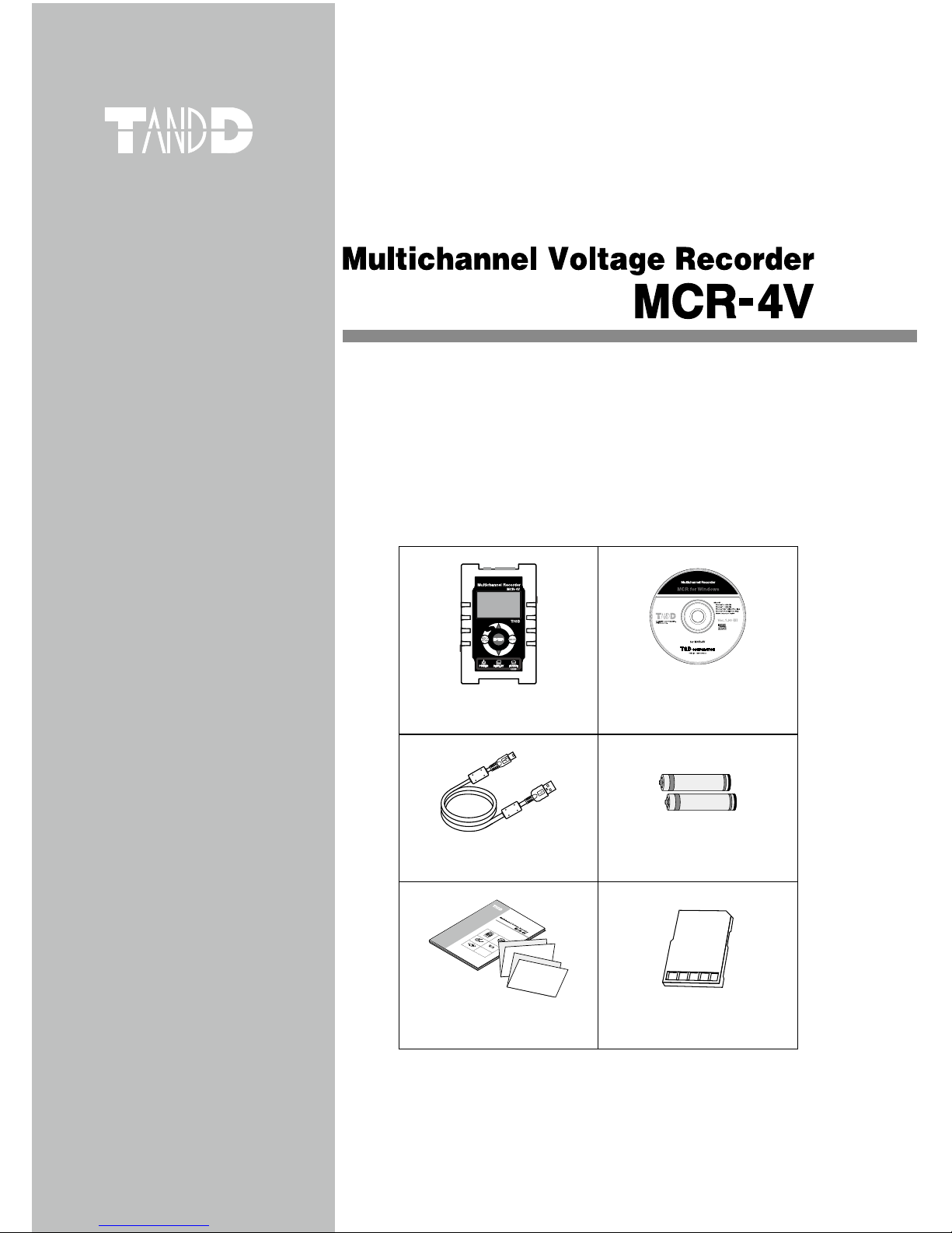
Please make sure the following items are included in the
package.
®
MCR-4V x 1 unit “MCR for Windows”
CD-ROM x 1
USB MIni-B Cable
(US-15C) x 1
AA Alkaline Battery (LR6)
x 2
© Copyright T&D Corporation. All rights reserved.
2013.04 16504820004(第2版)
取扱説明書
お買い上げありがとうございます。
本書ではMCR-4V 本体の取り扱いおよび使用方法につい
て説明しています。
パッケージには以下の物が含まれています。すべて入っ
ているか確認してください。
®
MCR-4V 1台MCR-4V for Windows
CD-ROM 1枚
USB通信ケーブル
US-15C1本
単3アルカリ電池
2本
取扱説明書・保証書(本書)
添付資料(2種) 各1部
User’s Manual Set
(Warranty Included)
Card Slot Cover x 1

Important Notices and Disclaimers
In order to properly use this product, please carefully read all documents
that accompany the product before using. T&D Corporation accepts no
responsibility for any malfunction of and/or trouble with this product or
with your computer that is caused by the improper handling of this
product and will deem such trouble or malfunction as falling outside the
conditions for free repair outlined in the attached warranty.
- All rights of the attached documents belong to T&D Corporation. It is
prohibited to use, duplicate and/or arrange a part or whole of the
attached documents without the permission of T&D Corporation.
- Microsoft and Windows are registered trademarks of Microsoft Corpora-
tion in the United States and/or other countries.
- Windows Vista is either a registered trademark or trademark of Microsoft
Corporation in the United States and/or other countries.
- All registered trademarks, company names, product names and logos
mentioned herein or for products being used are the property of T&D
Corporation or of their respective owners.
- Specications, design and other contents outlined in the attached
documents are subject to change without notice.
- Please follow the safety precautions outlined in the attached documents
carefully. We cannot guarantee nor are we responsible for safety if this
product is used in any manner other than was intended.
- On-screen messages in the attached documents may vary slightly from
the actual messages.
- Please notify the shop where you purchased this product or T&D
Corporation of any mistakes, errors or unclear explanations in the
attached documents.
- T&D Corporation accepts no responsibility for any damage or loss of
income caused by the use of our product.
- Accompanying documents cannot be reissued, so please keep them in a
safe place.
- Please read the warranty and provisions for free repair carefully.

1
Safety Precautions and Instructions
Safety Precautions and Instructions
The following items should be strictly obeyed for the safe usage of this
product, and for protecting yourself and other people from bodily harm
and/or damage to property.
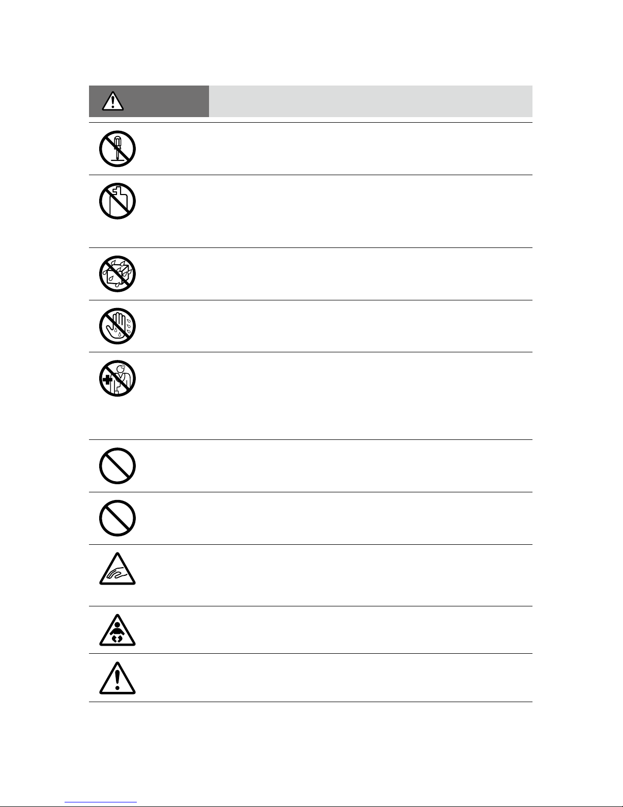
Explanation of Symbols
Warning Symbols
DANGER Failure to follow the instructions with this symbol
could cause serious injury or even death.
CAUTION
Failure to follow the instructions with this symbol
could cause personal injury or physical damage
to equipment.
Picture Symbols
Denotes an important warning or caution.
Denotes a forbidden action.
Denotes an action that should be carried out.
2
DANGER To Prevent Serious Accidents
Do not disassemble, repair or modify the unit and accessories.
Do not use the unit in any environment that is exposed to
chemicals and harmful gases. Doing so may cause corrosion and/
or other danger to the unit. Also, coming in contact with hazardous
substances may cause bodily harm to the user or people nearby.
This unit is not water resistant. If water or a foreign object enters
the case, immediately unplug the AC adaptor and stop using it.
Do not handle the unit, remove batteries or cables with wet hands.
This product has been designed for private and/or industrial use
only. It should not be used in situations where strict safety
precautions are necessary such as with medical equipment, or in
systems directly or indirectly connected with human life or
well-being.
Do not drop or expose the unit to a strong impact.
Do not cut or process the cords for the communication cables.
Also, do not twist, pull on or swing any of the cords.
To prevent damage to the unit from static electricity, remove static
electricity from your body by touching metal around you (such as a
door knob and window frame) before touching the unit.
Place and store the unit and accessories out of the reach of
children.
Do not use any power, battery, sensor, or cable other than those
specied by T&D Corporation.

3
We are not responsible for any damage, malfunction or trouble,
whether direct or indirect, caused by the use of our product.
Do not put anything on top of the cable. This may cause overheat-
ing.
Do not disconnect the USB cable during USB communication.
Doing so may cause adverse effects to the unit and/or PC.
Make sure that all cable plugs are inserted fully, so as not to cause
an improper connection. Also, when unplugging the cable from the
unit, do not pull the cord, but hold the connector to disconnect.
If the unit produces heat, emits smoke or a strange smell, or makes
unusual noises, immediately remove the batteries, unplug the
power, and stop using it. Also, unplug the unit from the PC.
If the unit is not to be used for a long period of time, remove
batteries. If left in the unit, the batteries may leak and lead to
malfunctioning. Install new batteries when starting or re-starting to
use a unit.
If there is a possibility that high voltage pulses which exceed the
measurement range may be applied, make ground connections,
either directly or with the surge arrester.
Make sure that there is no magnetic media or materials within one
meter from the device.
Magnetic materials may cause damage to data stored in magnetic
media.
Do not remove the SD card or turn off the power while writing data
to the SD card. This may result in damage to data.
Do not apply voltages higher than ±50V to the earth or terminals. It
may cause electrication or malfunction.

4
CAUTION Do not place or store in the following areas:
• Areas exposed to direct sunlight
• Areas exposed to excessive heat or high temperatures such as near re or
heating equipment
• Areas exposed to static electricity
• Areas exposed to strong magnetic elds
• Areas exposed to dampness
• Areas subject to condensation or wet areas
• Areas exposed to excessive vibration
• Areas exposed to excessive smoke, dust or dirt.
CAUTION Other Precautions
• Use the unit in the specied operating environment. Do not use it for any
purpose other than for which it was designed.
• Condensation may occur inside the case when a unit is moved from one
environment to another where there is a great difference in temperature.
• Do not use the unit in wet areas or places exposed to water such as
bathroom.
• When connecting the unit to your PC, make sure to follow all warnings
and directions from your computer manufacturer.
• We shall not guarantee the unit's operation if it has been connected to a
PC using a USB hub or a USB extension cable.
• Please take extra caution when plugging in and pulling out the USB plug
while another USB device such as CDD or HDD is in operation.
• Do not insert any foreign objects into any of the units' jacks.
• If the unit gets dirty, wipe it with a clean cloth.
• Make sure to remove dust and dirt from plugs of any cables.
• Battery terminals may provide insufcient contact due to age or vibration.
This may lead to data loss.
• If the unit is not to be used for a long period of time, for safety reasons
please remove the battery. If left in the unit, the battery may leak and lead
to malfunctioning.
• When an SD card is not inserted, insert the supplied card slot cover to
prevent the intrusion of dust.

5
Before Using this Product
Please be careful about the procedures for Installation.
(For USB communication between your computer and a MCR-4V)
In order to use a USB connection to communicate between the unit and
a computer, it is necessary to install the software and the USB device
driver.
Make sure to rst install the software before connecting the unit to a
computer.
If you connect the unit rst, the USB device driver may not
be installed properly.
If you have connected the unit to your computer before installing the
software, make sure to click [Cancel] in the Wizard window when it
pops up on the computer display. Then disconnect the USB
communication cable from the unit.

6
Table of Contents
Safety Precautions and Instructions ------------------------- 1
Before Using this Product ------------------------------------ 5
Overview
Appearance Diagram and Part Names ---------------------- 9
Touch Panel --------------------------------------------------------------10
Touch Panel Operation Methods --------------------------------------- 11
LCD Display and Icons -------------------------------------------------- 11
About How Data is Recorded -------------------------------- 14
Using SD Memory Cards ------------------------------------- 15
Supported Memory Cards ----------------------------------------------15
Using MCR-4V
Installing the Battery ----------------------------------------- 17
Usable Power Sources -------------------------------------------------- 17
Changing the Batteries --------------------------------------------------17
Measuring Voltage -------------------------------------------- 18
About the Measurements Display --------------------------------------18
About the Trend Graph Display -----------------------------------------19
Operating the Trend Graph ---------------------------------------------19
Increasing Recording Channels ----------------------------- 21
About Group Recording with MCR-4V and MCR-4TC ---------------21
Storage Location for Group Recording --------------------------------22
Group Operations via Master ------------------------------------------- 23
Starting Recording by Group -------------------------------------------23
Stopping Recording by Group------------------------------------------24
About Menus
[Record Settings] Menu -------------------------------------- 26
[Data List] Menu ---------------------------------------------- 28
Displayed Items when Recording Stopped: ---------------------------28
Displayed Items during Endless Recording: ---------------------------29
[Memory Card] Menu ----------------------------------------- 30
[Operation Settings] Menu ----------------------------------- 30

7
Overview Using MCR-4V
About Menus Using a PC with MCR-4V Other
Explanation of Items in Each Menu ------------------------- 31
[Record Settings] Menu Items ------------------------------------------ 31
[Data List] Menu Items (when recording stopped) --------------------38
How to Read Recorded Data Graph ----------------------------------- 39
[Data List] Menu Items (during endless recording) -------------------- 42
[Memory Card] Menu Items ---------------------------------------------44
[Operation Settings] Menu Items --------------------------------------- 45
Using a PC with MCR-4V
Installing the Supplied Software ---------------------------------------- 47
Connecting the Device to a PC ------------------------------ 49
Making Settings via PC -------------------------------------- 50
Channel Name -----------------------------------------------------------50
Scale Conversion Equation ---------------------------------------------50
Unit Settings -------------------------------------------------------------50
Downloading Recorded Data to a PC ----------------------- 51
Download Recorded Data using “MCR for Windows”----------------51
Recorded Data File ------------------------------------------------------ 52
Download Recorded Data from all Connected MCR-4V Units-------53
Analyzing Recorded Data ------------------------------------ 54
Open Recorded Data ----------------------------------------------------54
Print Graphs -------------------------------------------------------------54
Other
Troubleshooting ----------------------------------------------- 55
Specications ------------------------------------------------- 60
MCR-4V ------------------------------------------------------------------ 60
Software (MCR for Windows) ------------------------------------------- 62

8
Overview
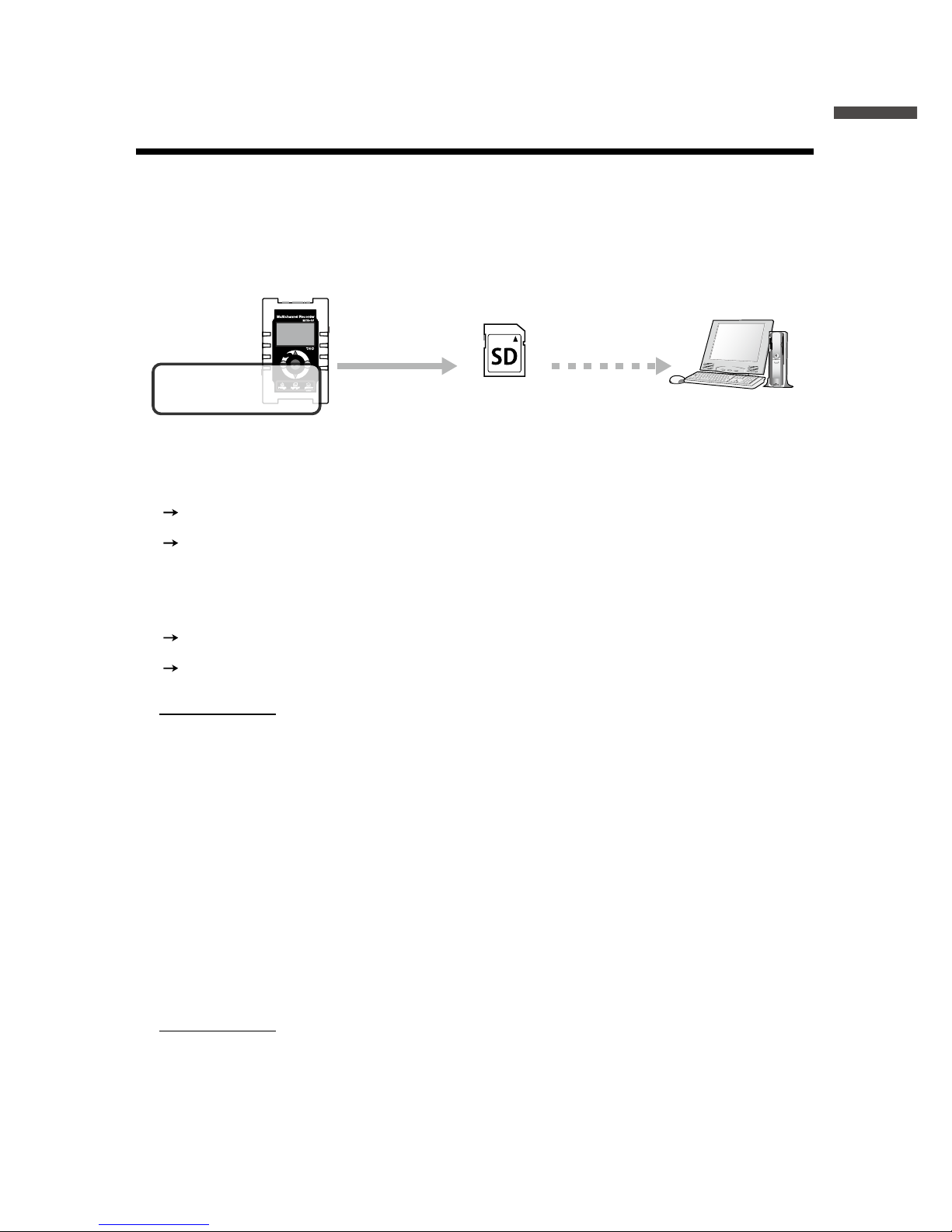
The MCR-4V is a multi-channel voltage data logger. It measures and
records voltage, and the data can be easily displayed in graph form,
enabling the immediate on-the-spot checking of continually-changing
data.
SD Memory Card
or
USB Connection
Measure and Record
Device Coupling
Image
Master Slaves
Measurements
and Trend Graph
Use “MCR for Windows” for
- Device Settings
- Recording Settings
- Downloading Recorded Data
Use “T&D Graph” for
- Graph Display
- Data Analysis
-
Printing and Saving in Text
Main Features in Rec Settings
- Average Value Recording
- 50-60Hz Filter
- Increase of Number of Channels
- Preheat
- Recording Stop Trigger
9
Overview
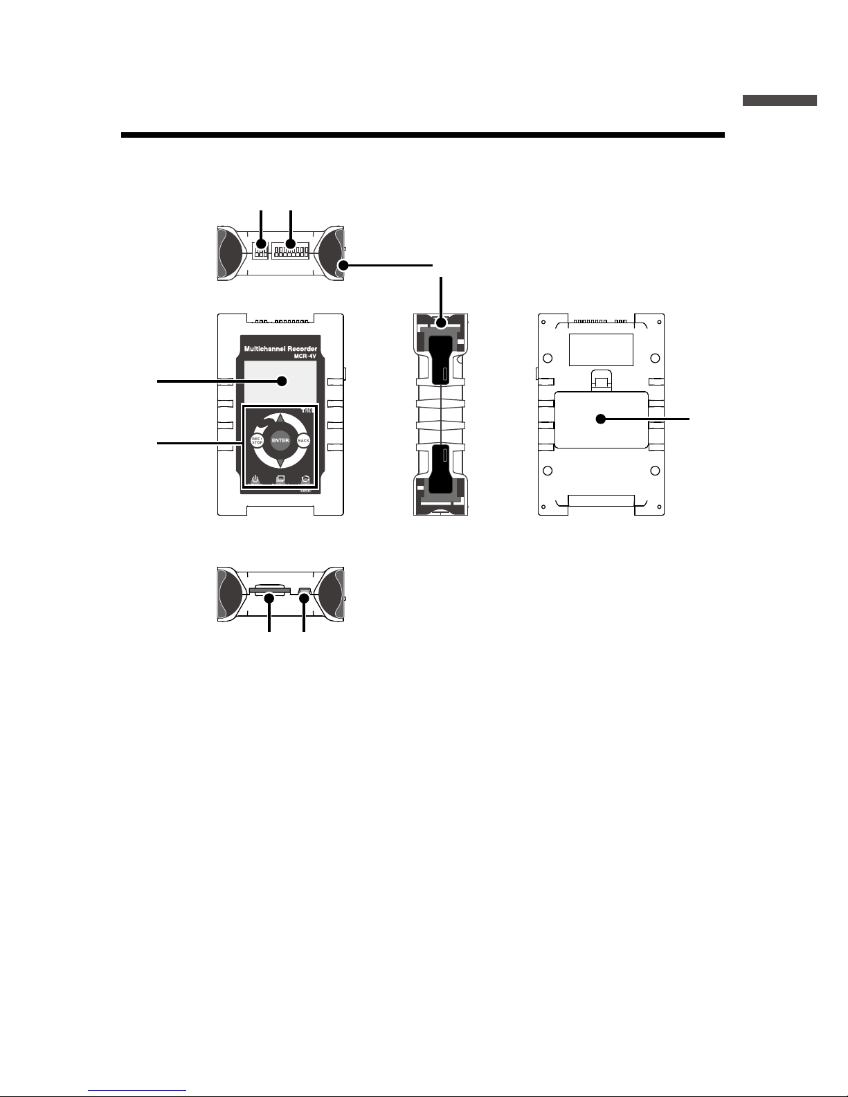
Appearance Diagram and Part Names
1. Preheat Terminal
2. Input Terminal
3. Coupling Lug
4. LCD Display
5. Touch Panel
(touchpad and control wheel)
6. SD Memory Card Slot
7. USB Port
8. Battery Cover
4.
5.
8.
3.
[TOP]
[FRONT] [SIDE] [BACK]
[BOTTOM]
2.1.
6. 7.
Throughout this manual, the MCR-4V is also referred to as “the device”
or “the unit”.

10
Touch Panel
Press to change the selected menu or settings item (by going
up or down), and to increase or decrease the values shown in
the LCD.
Press to conrm the selected menu, operation, or value.
Press to jump to the [Start Recording] or [Stop Recording]
menu.*
Press to return to the previous screen in the menu* or cancel
the current operation.*
Press and hold to turn the power ON/OFF.
Press to switch the display between [Menu] - [Measurements]
- [Trend Graph].
Press to switch between the touchpad operation and control
wheel operation. Press and hold to switch the key lock ON/OFF.
* Will not function when operating by control wheel.
11
Overview
Touch Panel Operation Methods
There are two ways to operate the touch panel as follows:
- Touchpad operation
- Control wheel operation
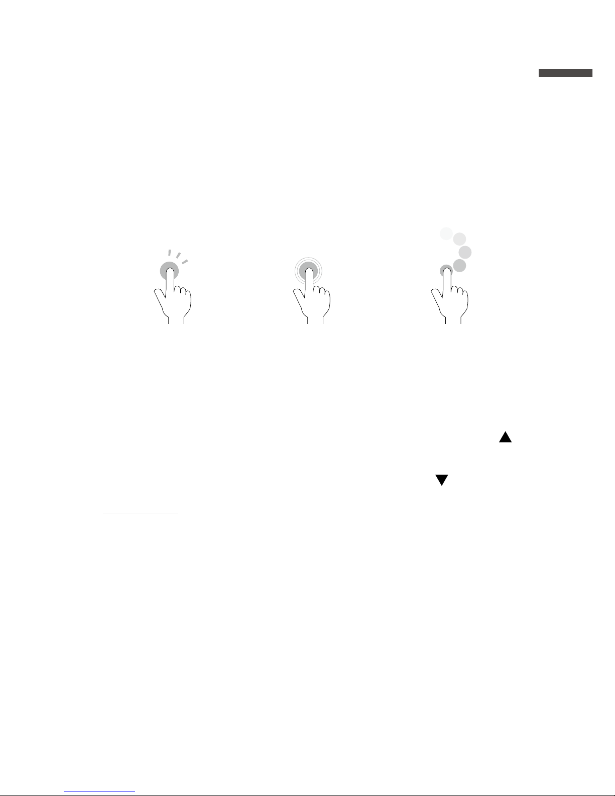
Terms and gestures related to operations
Tap
(touch)
Tap desired area of
touch panel.
Press-and-hold
(hold down)
Touch the screen and
hold nger in place
for a few seconds.
Mainly used to switch
ON/OFF the power
and key lock.
Control Wheel
Operation (rotate)
Press and rotate the
control wheel (white
circular area).
Clockwise
movement moves
(up) and counter-
clockwise movement
moves (down).
IMPORTANT
- During operation, if none of the above gestures are performed for a while, the operation
will be canceled and the screen will return to the original value or previous screen.
- Make sure to use a bare nger to operate the touch panel. If you use the tip of your
ngernail, gloves, or touch pen, touch panel operations may not be recognized.
Auto Power Off Function
If the device is not used for about three minutes, it will automatically turn
off to save battery power. However, the Auto Power Off function will be
disabled in any of the following situations.
- When a recording session is in progress
- When measurements or trend graphs are displayed on the screen
- When running on external power

12
LCD Display and Icons
The following contains some brief explanations about icons. Each menu
will be explained later in the “Menu List” pages.
A highlighted display
shows the item currently
selected, and a blinking
highlight shows that an
item is being changed.
LCD backlight will be
ON during operation.
7
8
7
1 2 3 4 5 6
1Recording Status Shows the recording status.
REC : Recording in progress
STP : Recording stopped
PRG : Waiting for programmed start
IMM : Preparing immediate start
TRG : Stopped by trigger
2Recording Mode Shows the recording mode.
: Endless mode
: One-Time mode
3Recording Interval Shows the recording interval.
ms : millisecond(s)
sec : second(s)
min : minute(s)
When the recording method is Average, “Aver.” and the
recording interval are displayed alternatingly.
When the recording method is Ave.Fine, “Ave.f” and the
recording interval are displayed alternatingly.
4
Recording Channels
Shows the channel(s) being measured and recorded.
5Battery Mark Shows source of power and battery level
/ Battery Mark (Alternating Display) : Running on
external power
Battery Mark only (see the next page) : Running
on battery
6Operation Mode Shows the operation mode status.
: Touchpad operation enabled
: Control wheel operation enabled
: Touch Panel disabled
7 These indicate that there are more menu items above or
below for view. Use and on the touch panel to scroll
up and down.

13
Overview
8An item marked with an arrow denotes it has been selected.
Use and on the touch panel to move the arrow up and
down. Press <ENTER> to execute the selected operation.
The battery mark shows the battery level as follows.
: Full or near full power
: Beginning to lose power
: Signicant loss of power
: Change batteries as soon as possible
: Change batteries immediately
: Not operable with batteries only
Below are some examples of recording conditions and the
corresponding estimated battery life.
4 channels, Instantaneous value, 10-ms interval : About 4.5 days
4 channels, Instantaneous value, 1-sec interval : About 120 days
4 channels, Instantaneous value, 10-sec interval : About 150 days
Power OFF : About 3 years
* Battery life varies depending upon the measurement conditions, operating
environment, and battery performance.

14
About How Data is Recorded
The MCR-4V records measurement data to its internal memory. A
recording session is one cycle from recording start to stop, and the
MCR-4V can record multiple sessions. The number of recording
sessions and number of data readings which can be recorded depends
upon the number of channels, the recording interval and other settings.
In the “n”th recording session, the remaining memory space is used for
recording.
EX: When logging capacity is lled during the 5th recording session:
1st
1st
2,000
readings
2,000
readings
2nd
2nd
3,000
readings
3,000
readings
3rd
3rd
5,000
readings
5,000
readings
4th
Internal Memory Capacity
4th
8,000
readings
8,000
readings
In Endless mode,
data will be overwritten from the
beginning of the 5th recording
session and recording will continue.
In One-Time mode,
recording will stop.
5th
5th
* If the memory capacity has not reached full, up to 30 recording sessions can be
made.
15
Overview
Using SD Memory Cards
It is not only possible to transfer data stored in the internal memory to
an SD memory card, but it is also possible to automatically backup data
while recording in endless mode. Operations related to the use of an SD
memory card are as follows:
Record in internal
memory
Copy data to a
memory card
Copy
to a PC
Exporting Data while Recording is OFF (Manual Saving) See p.38 for
details
[Data List]—[Export Selctd Data]
[Data List]—[Export All Data]
Exporting Data while Endless Recording is ON (Manual Saving /
Automatic Saving) See p.42 for details
[Data List]—[Expt Curr Data Now]
[Data List]—[Auto Data Export]
IMPORTANT
- Memory cards are not included. Please purchase separately.
- Measurement data cannot be directly recorded into a memory card.
- Before inserting an SD memory card into the device, make sure to switch off write
protection on the memory card.
- Exporting data to the memory card will not erase it from the device’s internal memory.
Delete recorded data in the device as necessary.
Supported Memory Cards
- SD Memory Cards
- SDHC Memory Cards
IMPORTANT
- SDXC memory cards cannot be used.
- It is possible to run a quick test to see if your memory card works in. See p.44 for details.

16
Using MCR-4V
The following shows the basic ow of procedures.
4.
Measuring and Recording
5.
Viewing Recorded Data in Graph on the Device (see p.39)
Use MCR-4V Use PC
3.
Setting up the Device (see p.30)/ Making Recording Settings (see p.26)
* Recording Settings can be made both on the device and from a PC.
2.
Getting PC Ready
Install the provided software (see p.47)
Connect the device to a PC (see p.49)
1.
Getting Device Ready
Install the batteries (see p.17)
6.
Downloading Recorded Data to a PC
Exporting data to an SD memory card and transferring to a PC. (see p.38)
Using the supplied software “MCR for Windows” (see p.51)
* Either of the above can be used to download recorded data to a PC.
7.
Analyzing Recorded Data on a PC (see p.54)
View Graph, Print, Save in Text
When not using a PC, the only necessary steps are
1
and
3
to
5
.
17
Using MCR-4V
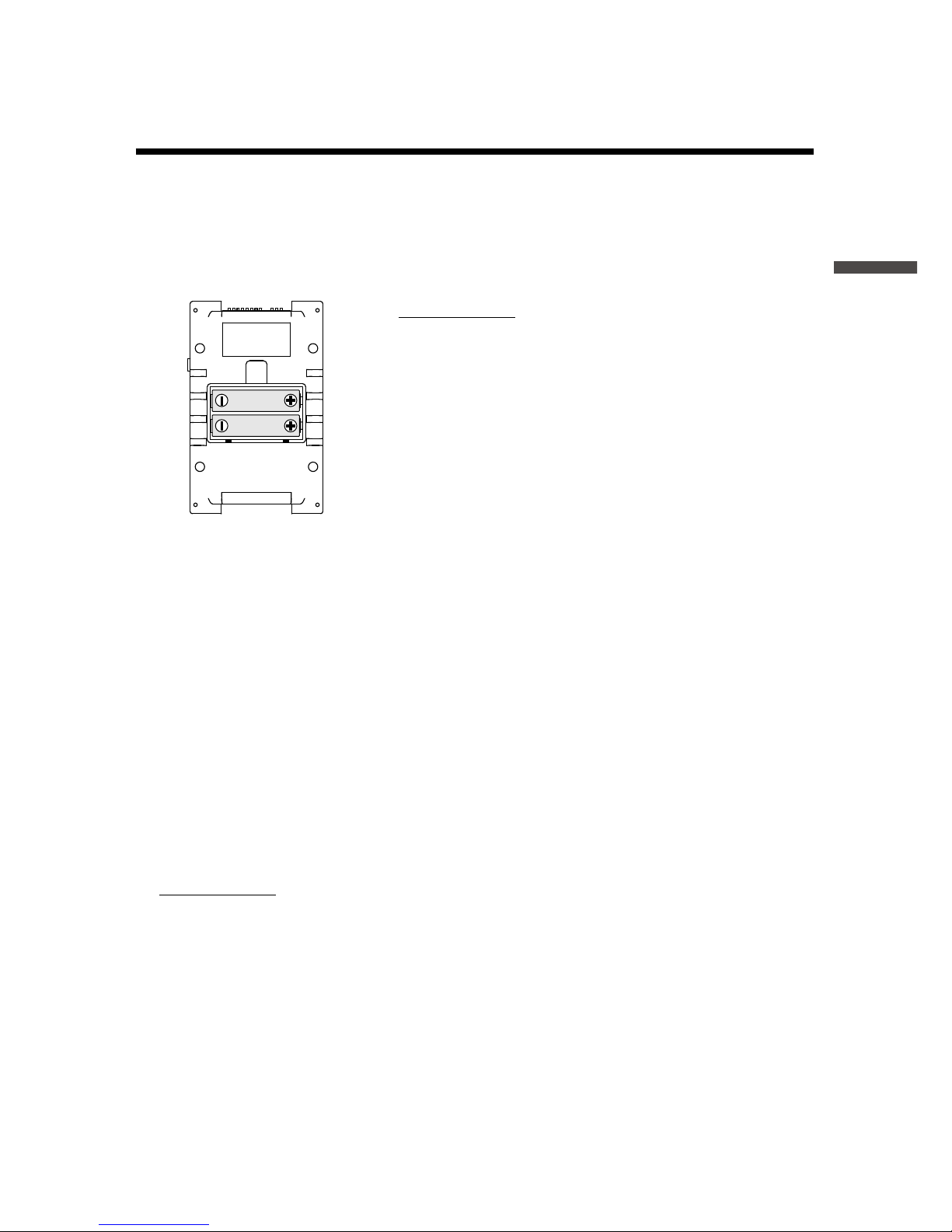
Installing the Battery
Remove the battery cover from the back of the device, and insert the
supplied two AA alkaline batteries as shown in the gure below.
After the batteries are inserted, the [Please set the clock] message will
appear on the LCD.
IMPORTANT
- Make sure to use new batteries of the same kind.
- Make sure not to mistake + / -.
- Do not insert or change batteries with wet hands.
- Be sure to completely close the cover.
- The MCR-4V cannot recharge batteries.
Usable Power Sources
- AA Alkaline Batteries
- AA Ni-MH Batteries
- AC Adapter (USB type)
- USB Bus Power
Changing the Batteries
If the battery runs down before it is replaced, MCR-4V will automatically
stop recording to protect data. Check the battery mark (see the previous
page) and change batteries as necessary.
IMPORTANT
- To protect data, please stop recording rst before changing batteries. Not doing so
may result in loss of data being recorded.
- When you wish to replace batteries while recording is in progress, make sure to
connect the USB cable to your PC for USB bus power.
- If the MCR-4V runs out of power while processing data on a SD memory card, the data
on the card may be corrupted.
18
Measuring Voltage
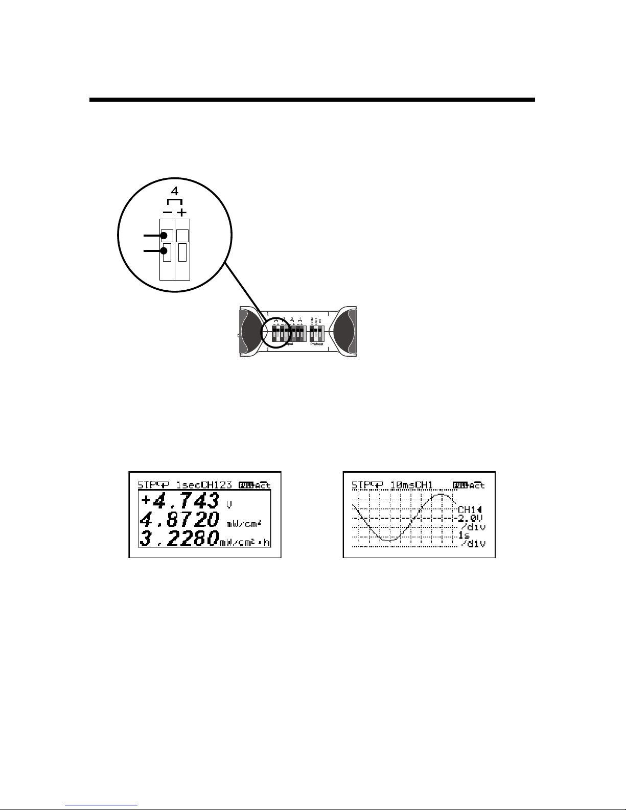
1.
Connect the item to be measured to the MCR-4V using a compatible
wire.
1. Prepare a compatible 10mm strip wire (see
Spec).
2. Using a screwdriver or other such tool, while
pressing down on the terminal button <B>
on the top of the device, insert the wire into
the hole <A>.
3. When removing the wire, push down on <B>
and gently pull the wire out of the hole <A>.
Enlarged View of
Input Terminal
Top Surface
A
B
* Absolute maximum input voltage is 50V.
* Maximum measurable input voltage is ±24V.
2.
Press <DISPLAY> to switch the LCD display, and view the
measurement and/or trend graph.
Measurements Trend Graph
About the Measurements Display
The font size used to display the measurement automatically changes
depending on the number of channels.
* You can change the number of channels by going to the Main Menu and selecting
[Record Settings] > [Rec.Channel]. To change the [Rec.Channel] setting, [Detailed
Sett.] needs to be set to ON.
* When using the scale conversion, the converted value and unit are displayed.
Other manuals for MCR-4V
2
Table of contents
Other T&D Voice Recorder manuals


Popular Voice Recorder manuals by other brands


Philips
Philips VOICE TRACER DVT2510 user manual

Edic
Edic EDIC-mini Tiny xD A69 Operation manual

Philips
Philips VoiceTracer DVT1120 quick start guide

Sony
Sony TCM-200DV - Cassette Recorder Specification sheet

Girl tech
Girl tech B-Bop 76028 instruction manual

TS-market
TS-market EDIC-mini TINY 16 A404 Short operating instructions