Tansun Quartzheat Monaco single SOR 215IP UK-M User manual

©Tansun Limited 2014 Part No. 042220-M Issue. 1a
F o l l o w i n g i n f o r m a t i o n i s o n l y f o r E U - m e m b e r s t a t e s :
The use of this symbol indicates that this product may not be treated as household waste. By ensuring this product is disposed
of correctly, you will help prevent potential negative consequences for the environment and human health, which could
otherwise be caused by inappropriate waste handling of this product. For more detailed information about recycling of this
product, please contact your local council, your household waste disposal service or the shop where you purchased the
product.
9. The emitter should now be removed from the heater as shown in Fig. M.
10. Refit the new emitter in reverse order ensuring that no wires get trapped and all screws are fully tightened.
Fig. M
Fig. L
8. The emitter the wires should be pulled out of the side slots and the emitter can be lifted up completely (Fig. L). The
wires should be gently pulled so they come out from behind the reflector.
Spectrum House, Unit 1, Ridgacre Road, West Bromwich,
West Midlands, B71 1BW, England.
Tel: +44 (0)121 580 6200 - Fax: +44 (0)121 580 6222
Reference Manual
Monaco
Single
UK & EUROPEAN MODELS:
SOR 215IP UK-M
SOR 215IP EU-M

Caution
When using Tansun electrical heaters, basic precautions should always be
followed to reduce the risk of fire, electric shock, and injury to persons,
including the following:
Read all instructions before using this heater.
•
Before using this appliance:
- Check that the voltage indicated on the type plate corresponds to the
mains supply voltage.
- Ensure that the heater has been securely fastened in it
s final mounting
position.
•
Do not locate the heater immediately below a socket outlet.
•
This appliance can be used by children aged from 8 years and above
and persons with reduced physical, sensory or mental capabilities or
lack of experience and knowledge if they have been given supervision
or instruction concerning use of the appliance in a safe way and
un
derstand the hazards involved. Children shall not play with the
appliance. Cleaning and user maintenance shall not be made by
children without supervision.
•
Children of less than 3 years should be kept away unless continually
supervised.
•
Children aged from 3 years and less than 8 years shall only switch on/
off the appliance provided that it has been placed or installed in its
in
tended normal operating position and they have been given
supervision or instruction concerning use of the appliance in a safe way
and understand the hazards involved. Children aged from 3 years and
less than 8 years shall not plug in, regulate and clean the appliance or
perform user maintenance.
•
CAUTION - Some parts of the product can become very hot and
cause burns. Particular attention has been given where children
and vulnerable people are present.
•
Remove the plug from the mains socket (or disconnect pole switch)
during installation, cleaning and/or replacing the element and always
ensure that the element is cool.
2 7
4. At the back of the heater, remove the plate holding the terminal box by removing the two fixing screws as shown in
Fig. G.
5. Pull the emitter wires one at a time through the plate to remove as shown in Fig. H.
6. At the front of the heater, the guard in front of the emitter you are replacing should be removed by gently pulling it
away from the heater so it prises out of its locating holes at each end (Fig. J).
Fig. G Fig. H
Fig. J
Fig. K
7. Remove the screw (Fig. K) from the side reflector and lift it up away from the heater to remove it. Repeat at opposite
end to remove other side reflector.

6
R e p l a c i n g t h e E m i t t e r
If you are in any doubt about following the procedure below, please contact us for technical assistance. The
mains power should be disconnected before any attempts are made to replace the emitter. The following should
be carried out with compliance to the latest electrical regulations. If you are unfamiliar with installing such fix-
tures, contact a qualified electrician to carry out.
1. Ensure the heater and emitter are cool and the power supply is disconnected by removing the plugs from the socket
outlet - all plugs must be removed even if only one emitter is to be replaced.
2. Remove the screws from the terminal box at the back of the emitter you wish to replace and lift off the lid - see Fig. E.
Fig. E Fig. F
M a i n t e n a n c e
In the event of heater failure, or for spare parts or advice, please contact Tansun Limited in the first instance.
Disconnect from the mains before commencing any maintenance procedure including cleaning.
To ensure optimum heat effectiveness, it is recommended that that the guard and emitter are removed and the reflector
is wiped with a lint-free cloth before reassembling should the reflector show considerable signs of dust or dirt.
H a n d l i n g t h e R e p l a c e m e n t E m i t te r
Your new emitter should not be handled with bare hands. Remove finger marks with a soft cloth and
methylated spirits or rubbing alcohol. Finger marks will burn into the emitters quartz glass causing
premature failure.
Y o u r R e p l a c e m e n t E m i t t e r
It is very important that your replacement emitter is exactly the same as the one it was supplied with. Failure to fit the
exact same type could cause the heater to fail or even become dangerous especially when used in an outdoor
environment. Please contact Tansun Limited to purchase your replacement emitter and state the model number of the
heater you wish to fit the emitter to.
3. Disconnect the emitter from the connector blocks by unscrewing the screws highlighted above in Fig. F and remove
the white coloured emitter wires from the terminal block.
•
Do not use an extension cord with this product because the extension
cord may overheat and cause a risk of fire.
•
Keep the mains supply cord away from the body of the heater which will
get hot during use.
•
Arrange the mains supply cord so it cannot be tripped over or damaged.
•
Do not cover or obstruct the heater while it is in use.
•
Do not insert any object through any slot or opening in the heater.
•
Do not use if a guard is not present.
•
Do not install less than the minimum mounting distance from the floor.
•
WARNING: This heater is not equipped with a device to control the
room temperature. Do not use this heater in small rooms when they are
occupied by persons not capable of leaving the room on their own,
unless constant supervision is provided.
•
Do not touch the heater when it is turned on, as the body gets hot.
•
Do not use the heater in a bathroom,
laundry areas and similar
locations. Never locate the heater where it may fall into a bathtub or
other water container.
•
Do not use in explosive atmospheres.
•
A heater has hot parts inside. Do not use it in areas where petrol, paint,
or flammable liquids are used or stored.
•
WARNING: This appliance must be connected to a supply that is
earthed!
I M P O R TAN T -
S AV E T H E S E I N S T R U C T I O N S F O R F U T U R E R E F E R E N C E
Ris k of Fire
Keep combustible materials such as furniture, papers, clothes and curtains
at least 1.8m (6 feet) from the front of the heater and away from the sides
and rear. If the heater is to be used outside, we recommend that a
waterproof or indoor socket outlet is used.
3

I n t r o d u c t i o n
The Monaco heater produces radiant heat like the sun, warming people and objects rather than the air in between. It is
mounted on an adjustable bracket that allows the heat to be directed exactly where it is required. Its attractive, lightweight
design means that it is effective yet unobtrusive. The Monaco is designed for indoor and outdoor use so is therefore
weatherproof.
Please read the following instructions carefully before use. The safety of this heater is guaranteed only by its
correct usage in accordance with these instructions, therefore it is recommended that they are retained for future
reference.
S p e c i f i c a t i o n
T a b l e 1 . U K a n d E u r o p e a n H e a t e r s
Voltage Total Current Min. height Min. dist. Min. dist. Dimensions Weight Ingress
Model (V) Power (A) from floor from ceiling from side W × H × D (kg) Protection
(W) (m) (m) wall (m) (mm) (IP)
SOR 215IP
*-M
230 1500 6.5 2.0 0.3 1.0 402 x 227 x 323 3.4 IP55
Use MCB Type 3 or C.
4
I n s t a l l a t i o n
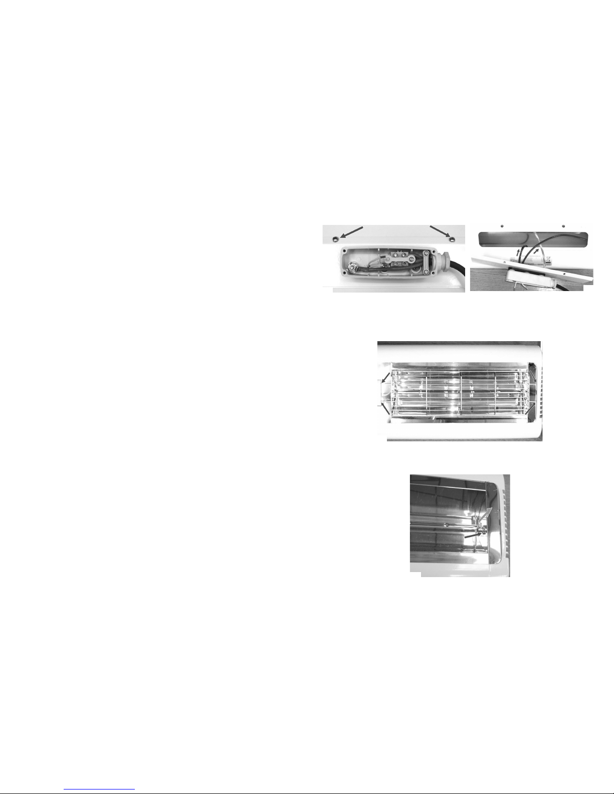
The Monaco heater is fitted with a supply cord and a moulded plug, therefore it is unnecessary to open the terminal box
in order to carry out normal installation of this product and should not be interfered with.
We recommend using a RCD where applicable.
Please observe the minimum safe distance between the heater body and any inflammable surfaces.
If the supply cord becomes damaged, it must be replaced by the manufacturer, its service agent or a similar qualified
person in order to avoid a hazard.
When the electrical connection is outside, it is recommended that a waterproof socket is used for the connection.
Otherwise, the plug should be connected to a socket indoors.
If in any doubt, please contact a suitably qualified electrician.
M o u n t i n g
The Monaco heater can be wall/surface mounted in a horizontal (Fig. A)
or angled manner (Fig. B) or hung from a ceiling (Fig. D) from chains (not
supplied).
When wall/surface mounting the Monaco heater in a horizontal manner,
do not position the heater at an angle more than 90° and less than 45° as
shown in Fig. A.
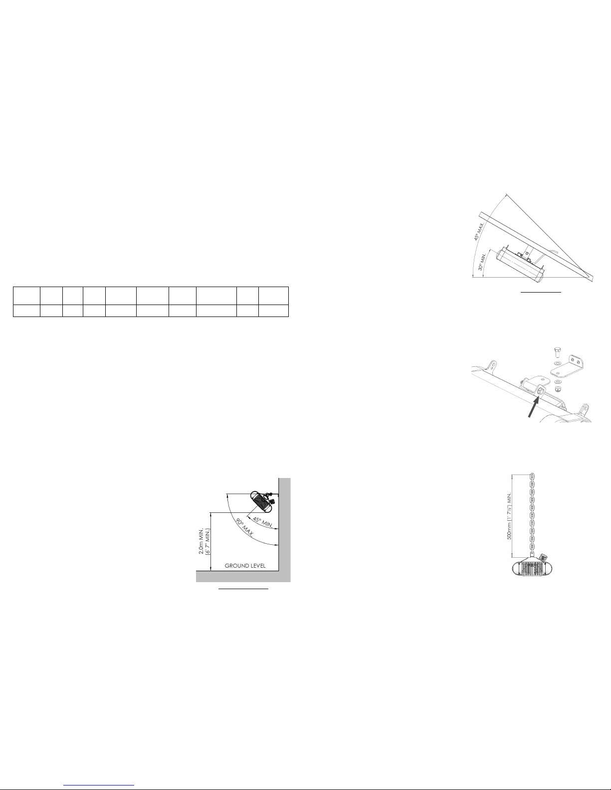
When surface mounting the Monaco heater in an angled manner, ensure
the mounting surface is angled so the heater projects downwards - see
Fig. C. Do not position the heater at an angle more than 45°and less than
30° to the horizontal as shown. Position the heater so the cord is exiting
the terminal box pointing down.
When ceiling hanging the Monaco heater, ensure the minimum distance
from the ceiling is adhered to as shown in Fig. D.
continued...
HORIZONTAL MOUNTING
Fig. A
Always allow the heater to cool before attempting to
reposition/move. Never attempt to move the heater while it is
switched on!
Observe the minimum safe distance between the heater body
and inflammable surfaces and objects when mounting.
Please refer to Table 1 for the recommended positioning of
the heater with regards to minimum distances. Do not install
the heater in a corner!
Do not mount the heater on plastic soffits and fascia boards
and ensure the mounting surface will suitably withstand the
radiant heat from the heater body.
Keep out of the reach of children.
1. When wall mounting, securely fasten the L-shaped wall
bracket to the mounting surface using both of the fixing holes in
the short part of the bracket. Refer to Table 1 for recommended
positioning of the heater. Please note: wall fixings are not
supplied. They should be selected to substantially support the
weight of the installation. If in doubt contact a professional for
advice!
2. The heater can be fixed to the wall bracket securely with the
nuts and bolts provided as shown in Fig. C.
3. The heater should be mounted with the terminal box at the
bottom of the heater.
4. When wall mounting, fix in the required angular position by
tightening the fixing bolt on the brackets at the rear of the heater
as pointed out in Fig. C.
5. Secure the supply cable so it is not resting on the body or
obstructing the air-vents.
Always isolate the heater from the mains supply when
adjusting the position.
ANGLED MOUNTING
5
Fig. C
Fig. B
Fig. D
ANGLEDMOUNTINGSURFACE
1. Please refer to Table 1 for recommended positioning of the
heater. When hanging from a ceiling two chains of equal
length and gauge are required and should be selected with
fixings that are adequate to hold the weight of the heater. If in
doubt contact a professional for advice!
2. Fix the heater assembly to the chains via the holes in the tabs
on the end castings as shown in Fig. D. and ensure the heater
faces directly down when hanging.
3. Secure the supply cable so it is not resting on the body or
obstructing the air-vents.
Always isolate the heater from the mains supply when
adjusting the position.
C e i l i n g H a n g i n g