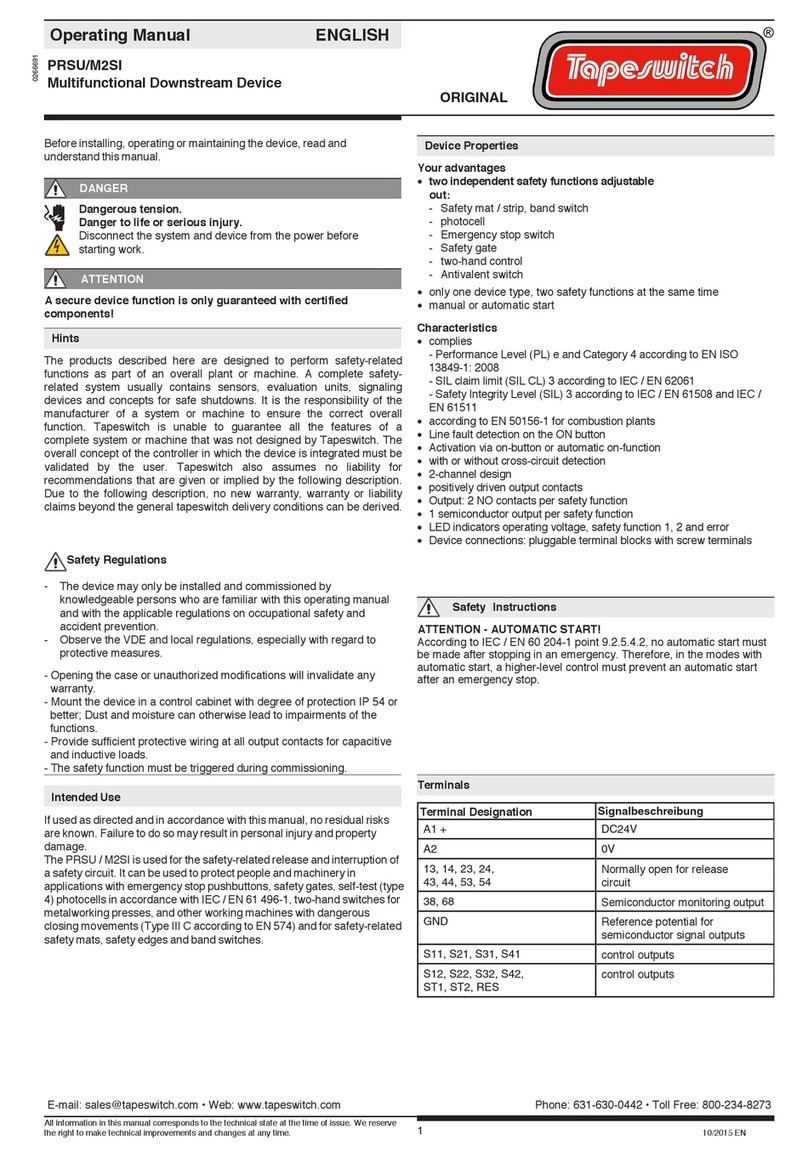
Tapeswitch PRSU/2 Instruction Manual

© Copyright (2021) All rights reserved. Changes, which serve technical improvements are reserved.
1
PRSU Series, Operating Instructions Manual (Revision 1.0)
TAPESWITCH CORP.
100 Schmitt Boulevard
Farmingdale
New York 11735
Phone: 800-234-8273
Fax: 631-630-0454
info@tapeswitch.com
www.tapeswitch.com
Introduction
This operating instruction shall familiarize you with the safety relay controller
models: PRSU/2, PRSU/4 and PRSU/5.
Target Audience
These operating instructions are addressed to the following personnel:
▪Skilled personnel who plan or develop safety equipment for machines
and plants, who are familiar with the safety instructions and safety
regulations.
▪Skilled personnel who build, install, maintain and operate safety
equipment in plants and machinery.
Symbol Key
These operating instructions contain several symbols which are used to
highlight important information:
This symbol indicates text passages which must absolutely be paid attention
to. Disregarding may lead to serious personal injury or damage to property.
This symbol indicates text passages which contain important information.
This sign is used to indicate actions by the installer or operator.
This sign illustrates that a condition has changed after an action has been
carried out.
PRSU/2, PRSU/4, PRSU/5
Operating Instructions Manual
Safety controllers for safety mats and
sensing edge products

© Copyright (2021) All rights reserved. Changes, which serve technical improvements are reserved.
2
PRSU Series, Operating Instructions Manual (Revision 1.0)
Safety Indications
Intended
Application
The safety relays PRSU/2, PRSU/4 and PRSU/5 are intended for the use with:
▪Single or dual-channel capability safety mats.
▪Single or dual-channel capability sensing edges, bumpers or ribbon
switches.
Operator and asset protection are only guaranteed if the safety relay is
operated according to its intended purpose and within the limits stated in its
specification.
Please pay attention to the following points:
Safety Warning
▪The device must be wired and operated by specialized staff who are
familiar with the current regulations for safety at work and accident
prevention and who have read this manual´s content in full. Installation,
assembly and maintenance of electrical equipment is only permitted by
specialized staff.
▪Pay attention to valid regulations, particularly in reference to preventative
measures.
▪Any repairs or modifications that are attempted outside of a Tapeswitch
factory, or by personnel that are not authorized by the manufacturer may
render the unit unreliable to serve as a safety component and should be
replaced immediately. Unauthorized modification will immediately void any
warranty.
▪Avoid mechanical vibrations more than 5g/33 Hz during transportation,
installation and operation.
▪The unit should be panel mounted in an enclosure rated IP 54 or better.
Dust and dampness could lead to malfunction.
▪Adequate fuse protection must be provided on all output contacts
with capacitive and inductive loads.

© Copyright (2021) All rights reserved. Changes, which serve technical improvements are reserved.
3
PRSU Series, Operating Instructions Manual (Revision 1.0)
PRSU/2 Electrical Overview
The PRSU/2 can be operated with an input voltage of +24VDC, or 24VAC. This model
features two normally-open safety relays that are triggered by the “Sensor Monitoring”
terminals (S11, S12, S21, S22).
Terminals
Description
A1
Power input (+24VDC,or 24VAC )
A2
Power input (GND, or 24VAC)
13, 14
Safety Relay #1
23, 24
Safety Relay #2
S33, S34
RESET Mode Control
S11, S12
Sensor Connection
S21, S22
Sensor Connection
Figure 1: Functional Schematic (PRSU/2)
Table 1: Device Terminals (PRSU/2)

© Copyright (2021) All rights reserved. Changes, which serve technical improvements are reserved.
4
PRSU Series, Operating Instructions Manual (Revision 1.0)
PRSU/4 Electrical Overview
The PRSU/4 can be operated with an input voltage of +24VDC, or 24VAC. This model
features three normally-open safety relays that are triggered by the “Sensor Monitoring”
terminals (S11, S12, S21, S22). This model also features an additional normally-closed
auxiliary relay (not for safety use).
Terminals
Description
A1
Power input (+24VDC, or 24VAC )
A2
Power input (GND, or 24VAC)
13, 14
Safety Relay #1
23, 24
Safety Relay #2
33, 34
Safety Relay #3
41, 42
Auxiliary Relay (Non-Safety)
S33, S34
RESET Mode Control
S11, S12
Sensor Connection
S21, S22
Sensor Connection
Figure 2: Functional Schematic (PRSU/4)
Table 2: Device Terminals (PRSU/4)

© Copyright (2021) All rights reserved. Changes, which serve technical improvements are reserved.
5
PRSU Series, Operating Instructions Manual (Revision 1.0)
PRSU/5 Electrical Overview
The PRSU/5 can be operated with an input voltage of 115VAC. This model features three
normally-open safety relays that are triggered by the “Sensor Monitoring” terminals (S11,
S12, S21, S22). This model also features an additional normally-closed auxiliary relay
(not for safety use).
Terminals
Description
A1
Power input (115VAC)
A2
Power input (115VAC)
13, 14
Safety Relay #1
23, 24
Safety Relay #2
33, 34
Safety Relay #3
41, 42
Auxiliary Relay (Non-Safety)
S33, S34
RESET Mode Control
S11, S12
Sensor Connection
S21, S22
Sensor Connection
Figure 3: Functional Schematic (PRSU/5)
Table 3: Device Terminals (PRSU/5)

© Copyright (2021) All rights reserved. Changes, which serve technical improvements are reserved.
6
PRSU Series, Operating Instructions Manual (Revision 1.0)
Device Startup Verification (PRSU/2)
Before creating any electrical connection to the device´s relay channels, RESET circuit, or
switch monitoring terminals, select a power supply with appropriate voltage settings and ensure
its output is set OFF.
Connect the power supply output (with appropriate input power source; see requirements listed
on Pages 13 and 14 of this manual) to the PRSU/2 power input terminals (A1, A2), then apply
the correct voltage for the device and verify that the “Power” LED illuminates.
Turn OFF power from the supply and make the appropriate connections to the switch monitoring
channels, relays and RESET circuit according to the configuration guidelines laid out on Pages
8 through 10 of this manual.
When the correct configuration is implemented and power is again applied, monitoring of the
switches/sensors will only occur once a RESET signal is received by bridging S33 and S34 with
an appropriately rated wire. See pages 8 through 10 of this manual for more information.
After the RESET signal is received and the monitored switch is in the unactuated state, the relay
contacts (13 →14), (23 →24) will close.
Device Startup Verification (PRSU/4, PRSU/5)
Before creating any electrical connection to the device´s relay channels, RESET circuit, or
switch monitoring terminals, select a power supply with appropriate voltage settings and ensure
its output is set OFF.
Connect the power supply output (with appropriate input power source; see requirements listed
on Pages 13 and 14 of this manual) to the PRSU/4 or PRSU/5 power input terminals (A1, A2),
then apply the correct voltage for the device and verify that the “Power” LED illuminates.
Turn OFF power from the supply and make the appropriate connections to the switch monitoring
channels, relays and RESET circuit according to the configuration guidelines laid out on Pages
8 through 10 of this manual.
When the correct configuration is implemented and power is again applied, monitoring of the
switches/sensors will only occur once a RESET signal is received by bridging S33 and S34 with
an appropriately rated wire. See Pages 9 through 10 of this manual for more information.
After the RESET signal is received and the monitored switch is in the unactuated state, the relay
contacts (13 →14), (23 →24) and (33 →34) will close. Contacts (41 →42) will open.

© Copyright (2021) All rights reserved. Changes, which serve technical improvements are reserved.
7
PRSU Series, Operating Instructions Manual (Revision 1.0)
Recommended Limits
Performance of the PRSU/2, PRSU/4 and PRSU/5 are limited according to the values listed on
Pages 13 and 14 of this manual. In particular, a 200Ω limit on short-circuit (actuated state) series
resistance is required for four-wire, fail-safe applications. The overall series resistance of different
products, cables and layouts can vary greatly. To ensure that a particular application will require
only a single PRSU/2, PRSU/4 or PRSU/5, the following rule-of-thumb guidelines can be used:
Recommended Application Limits
Product Type
Maximum Area
Maximum Length
ControlMat, ArmorMat, DPM
100ft²
N/A
Sensing Edge Products (all)
N/A
200ft
Ribbon Switches
N/A
200ft
SE-45, SE-75, SE-C Bumpers
N/A
200ft
All values listed assuming 20AWG/4, Ø3/16, lead cable @ 500ft max.
Table 4: Safety Product Recommended Limits
Common Device Configurations
See below for graphical representation of lead styles.
Product Type
S11
S21
S12
S22
Single Lead, Fail-safe
BLACK
RED
YELLOW
WHITE
Dual Lead, Fail-safe, Style 1
BLACK1
WHITE1
BLACK2
WHITE2
Dual Lead, Fail-Safe, Style 2
RIBBED1
SMOOTH1
RIBBED2
SMOOTH2
Table 5: Common Wiring Configurations

© Copyright (2021) All rights reserved. Changes, which serve technical improvements are reserved.
8
PRSU Series, Operating Instructions Manual (Revision 1.0)
Device Mounting and Unmounting
Mechanical
Mounting
All units should be DIN-rail mounted and/or panel-mounted in an enclosure rated at IP
54 or better. Dust and dampness could lead to malfunction.
▪There is a notch on the rear of the unit for DIN-Rail attachment.
Electrical
Connections
Wire the device based on which of the following options best suits the target
application:
RESET Mode Control Wiring:
1. Automatic:
In this operating mode, the output relay coils will become energized
automatically if and only if a properly working safety sensor is
appropriately connected and unactuated. Implement this mode of operation
by electrically bridging the device´s S33 and S34 terminals with a wire.
Figure 4: DIN Rail Mounting Detail
Figure 5: RESET Mode (Automatic) Configuration

© Copyright (2021) All rights reserved. Changes, which serve technical improvements are reserved.
9
PRSU Series, Operating Instructions Manual (Revision 1.0)
2. Manual:
In this operating mode, the output relay coils will de-energize upon
the closure of conductors within the monitored sensor/switch system.
The coils will not energize again until the closure is broken and a
RESET signal is manually generated by the operator (via a mechanical
N.O. pushbutton or switch).
3. Conditional:
In this operating mode, the RESET signal cannot propagate
unless all of the following conditions are met:
- The contacts have opened in the monitored sensor/switch.
- The machine primary control elements (MPCE 1 and MPCE 2)
have closed.
- A manual RESET signal is subsequently generated by an
operator pressing the “Start” pushbutton.
Figure 6: RESET Mode (Manual) Configuration
Figure 7: RESET Mode (Conditional) Configuration

© Copyright (2021) All rights reserved. Changes, which serve technical improvements are reserved.
10
PRSU Series, Operating Instructions Manual (Revision 1.0)
Monitoring Channel Mode Wiring
For both of the following configurations, please note the maximum and minimum
electrical parameters for these devices listed in the table on Pages 13 and 14.
1. Dual channel (fail-safe):
For fail-safe (safety) applications, the following configuration must
be used:
This configuration ensures that the full length of all switch/sensor
conductors are monitored. If the switch/sensor’s conductors are
compromised at any point along their length, the controller will detect the
fault and cause the output relay to de-energize.
Warning: For this configuration to work as intended, the series
resistance between each end of the sensor’s conductors cannot exceed
10Ω. Additionally, the short circuit resistance between both of the
switch/sensor’s conductors cannot exceed 200Ω.
(Up to Category 3, SIL2, PLd Unreachable).
2. Single channel (Non-Safety):
For non-failsafe applications (non-safety), utilize the following
configuration where one side of each switch/sensor´s conductors is
connected to a monitoring terminal:
Single Lead / Single channel
Warning: This configuration does NOT provide detection of a
broken conductor/malfunctioning switch and is therefore
unsuitable for safety-related applications. For such applications, do
NOT use this configuration and opt for a “Dual Channel” fail-safe
configuration instead.
Figure 8: Dual-Channel (With Wire-Break Safety) Configuration
Figure 9: Single-Channel (Non-Safety) Configuration

© Copyright (2021) All rights reserved. Changes, which serve technical improvements are reserved.
11
PRSU Series, Operating Instructions Manual (Revision 1.0)
Maintenance Info and Replacement Procedure
The safety relay controller works without maintenance.
For replacement of the device, follow the procedure below:
1. Turn OFF and disconnect the source of applied power to the device.
Ensure that no terminal of the device is connected to a live voltage before continuing.
2. Unscrew terminals A1 and A2 from the device before removing any other connections.
3. One at a time, free connections from the device’s terminal blocks by
unscrewing. Ensure that freed conductors are not left in the vicinity of live voltage
conductors.
4. Insulate wire ends if necessary.
5. When all connections are freed, remove the defective device from the DIN rail.
6. Mount new device to the DIN rail (see Page 8, Figure 4).
7. Perform “Device Startup Verification” procedure described earlier on Page 6 of this
manual.

© Copyright (2021) All rights reserved. Changes, which serve technical improvements are reserved.
12
PRSU Series, Operating Instructions Manual (Revision 1.0)
Fault Diagnostic and Subsequent Measures
If the controller appears to be operating erroneously, please use the following
diagnostic guide to determine what action should be taken.
Ground fault AC/DC
(with electronic fuse
protection)
If the input fuse blows and the output contacts open, safely locate the source
of the fault and correct it, then replace the input fuse and follow the “Device
Startup Verification” procedure on Page 6 of this manual. If normal operation
of the device does not resume, retire the device and send to Tapeswitch
Corporation for evaluation.
Faulty/welded
Contact
In the case of welded contacts, the device can no longer implement its
intended function. Retire this device and send back to Tapeswitch
Corporation for evaluation.
Only one or no
LED illuminates
In cases where either one or both “Channel” LEDs is OFF during normal
operation, please verify that the device is properly wired. If the problem
persists, the device is no longer capable of service. Retire the device and
send to Tapeswitch Corporation for evaluation.
Excessive contact-
to-contact resistance
In cases where the device does not appear to operate properly, perform the
following checks (cables removed from controller ports):
1. Upper (cables between S22 and S21) conductor plus total cable
resistance in the unactuated state. Must be less than 10Ω.
2. Lower (cables between S11 and S12) conductor plus total cable
resistance in the unactuated state. Must be less than 10Ω.
3. Upper to lower (cables going from S11 to S21) conductor plus total
cable resistance. Measure at both sides (includes S21 to S22) during
actuation. Must be less than 200Ω.
If the results exceed the stated limits, the system will need one or more
additional controllers to conform to the maximum resistance parameters per
relay.
If the results are within the allowable limits and the controller is still not
working, contact Tapeswitch as the unit is likely faulty.

© Copyright (2021) All rights reserved. Changes, which serve technical improvements are reserved.
13
PRSU Series, Operating Instructions Manual (Revision 1.0)
Technical Data (PRSU/2)
Electrical data
Supply Voltage UV
PRSU/2
24VDC Or 24VAC
Voltage Range
UV ± 10%
Frequency
48Hz (min) to 62Hz (max)
Power Consumption (typ.)
+24VDC: 2.5W, 24VAC: 2.5VA
4-Wire Safety Switches
Maximum Short Circuit Resistance
<= 5
Maximum Signal Wires Resistance
<= 1
Conductor Data
Conductor Connection
2 x 1.5 mm2solid wire
2 x 1.5 mm2stranded wire-end ferrule
UL: Use 60/75°C copper wire only!
Max. Conductor Length (input circuit)
2 x 100m (Single channel)
4 x 100m (Dual channel)
Conductor Cross-Section
1.5 mm2
Capacitance/cable length
150 nF/km (maximum)
Reference Temperature
+ 25°C
Contact Data
Contact Allocation
2 N.O. safety
Contact Type
Relay positive guided
Contact Material
AgSnO2or comparable material
Switching Voltage
250VAC, 24VDC
Max. Switch/Relay Current
6A (individual), 13.8A (combined)
Min. Switching Current
10mA
Max. Switching Capability (per relay)
DIN EN 60947-5-1
AC 15 3 A
DC 13 3 A
Max. Switching Capacity
1500 VA (resistive load)
Mechanical Lifetime
107switching cycles
Creeping Distance and
Clearance
-EN 50178 at pollution grade 2, over voltage category 3 / 250V
-Basis isolation: over voltage
category 3 / 250 V
Contact Security
NO contact: 6.3A brief or 4A inert
Short Circuit Withstand
(IEC60947-5-1)
Weld Free Protection at IPSCC≥1kA SCPD
(Short Circuit Protection Device)
(Fuse links), size D01
acc IEC IEC60269-1; IEC60269-3-1; VDE036-
T301
NO-contacts: 10A
Restarting Readiness Time (minimum switch off
time the inputs)
0.5 s
Delay on De-energisation
24V DC: < 30 ms, 24V AC: < 70ms
Mechanical Data
Housing Material
Polyamide PA 6.6
Dimensions (W x H x D)
22.5mm x 114.5mm x 99mm
Fastening
Click-fastening for DIN-Rail
Humidity
95% 0-50°C
Torque Setting for Connection Terminals
0.5 Nm (min), 0.6 Nm (max)
UL: Overtorquing may cause
enclosure breakage
Weight with Terminals
Max. 185g
Storage
In dry areas
Environmental data
Operating Temperature
-25°C ... +55°C ( UL:…+40°C)
Terminal Type
IP 20
Housing Type
IP 40
Shock Resistance of N.O Contacts
5g, 33Hz
Certifications
Tested I.A.W.
EN ISO 13849-1
Achieved Level/Category
Performance Level e, Cat. 4
DC
99% (high)
CCF
Achieved
MTTFD
69 years (high)
PFHD
3.8 * 10-8 1/h

© Copyright (2021) All rights reserved. Changes, which serve technical improvements are reserved.
14
PRSU Series, Operating Instructions Manual (Revision 1.0)
Technical Data (PRSU/4, PRSU/5)
Electrical data
Supply Voltage UV
PRSU/4
24VDC Or 24VAC
PRSU/5
115VAC
Voltage Range
UV ± 10%
UV ± 10%
Frequency
48Hz (min) to 62Hz (max)
48Hz (min) to 62Hz (max)
Power Consumption (typ.)
+24VDC: 3W, 24VAC: 5VA
5VA
4-Wire Safety Switches
Maximum Short Circuit Resistance
<= 200
<= 200
Maximum Signal Wires Resistance
<= 10
<= 10
Conductor Data
Conductor Connection
2 x 1.5 mm2solid wire
2 x 1.5 mm2stranded wire-end ferrule
UL: Use 60/75°C copper wire only!
2 x 1.5 mm2solid wire
2 x 1.5 mm2stranded wire-end ferrule
UL: Use 60/75°C copper wire only!
Max. Conductor Length (input circuit)
2 x 100m (Single channel)
4 x 100m (Dual channel)
2 x 100m (Single channel)
4 x 100m (Dual channel)
Conductor Cross-Section
1.5 mm2
1.5 mm2
Capacitance/cable length
150 nF/km (maximum)
150 nF/km (maximum)
Reference Temperature
+ 25°C
+ 25°C
Contact Data
Contact Allocation
3 N.O. safety, 1 N.C. aux
3 N.O. safety, 1 N.C. aux
Contact Type
Relay positive guided
Relay positive guided
Contact Material
AgSnO2or comparable material
AgSnO2or comparable material
Switching Voltage
240VAC, 24VDC
240VAC, 24VDC
Max. Switch/Relay Current
5A (individual), 13.8A (combined)
5A (individual), 13.8A (combined)
Min. Switching Current
10mA
10mA
Max. Switching Capability (per relay)
DIN EN 60947-5-1
AC 15 230 V / 5 A
DC 13 24 V / 5 A
AC 15 230 V / 5 A
DC 13 24 V / 5 A
Max. Switching Capacity
1200 VA (resistive load)
1200 VA (resistive load)
Mechanical Lifetime
107switching cycles
107switching cycles
Electrical Lifetime
105switching cycles (DC 24V/2A)
105switching cycles (DC 24V/2A)
Creeping Distance and
Clearance
-EN 50178 at pollution grade 2, over voltage
category 3 /250V
-Basis isolation: over voltage
category 3 / 250 V
-EN 50178 at pollution grade 2, over voltage
category 3 /250V
-Basis isolation: over voltage
category 3 / 250 V
Contact Security
NO contact: 6.3A brief
NC contact: 4A gL/gG
NO contact: 6.3A brief
NC contact: 4A gL/gG
Short Circuit Withstand
(IEC60947-5-1)
Weld Free Protection at IPSCC≥1kA SCPD
(Short Circuit Protection Device)
(Fuse links), size D01
acc IEC IEC60269-1; IEC60269-3-1; VDE036-T301
NO-contacts: 6A
NC-contacts: 6A
NO-contacts: 6A
NC-contacts: 6A
Restarting Readiness Time (minimum switch off
time the inputs)
0.5 s
0.5 s
Delay on De-energisation
< 30 ms, 24V AC: < 50ms
< 30 ms
Mechanical Data
Housing Material
Polyamide PA 6.6
Polyamide PA 6.6
Dimensions (W x H x D)
22.5mm x 114.5mm x 99mm
22.5mm x 114.5mm x 99mm
Fastening
Click-fastening for DIN-Rail
Click-fastening for DIN-Rail
Humidity
95% 0-50°C
95% 0-50°C
Torque Setting for Connection Terminals
0.5 Nm (min), 0.6 Nm (max)
UL: Overtorquing may cause
enclosure breakage
0.5 Nm (min), 0.6 Nm (max)
UL: Overtorquing may cause
enclosure breakage
Weight with Terminals
Max. 180g
Max. 180g
Storage
In dry areas
In dry areas
Environmental data
Operating Temperature
-25°C ... +55°C ( UL:…+40°C)
-25°C ... +55°C ( UL:…+40°C)
Terminal Type
IP 20
IP 20
Housing Type
IP 40
IP 40
Shock Resistance of N.O./N.C. Contacts
8/2g
8/2g
Certifications
Tested I.A.W.
EN ISO 13849-1
EN ISO 13849-1
Achieved Level/Category
Performance Level e, Cat. 3
Performance Level e, Cat. 3
DC
90% (Medium - redundant switch off channel
with monitoring)
90% (Medium - redundant switch off channel with
monitoring)
CCF
Achieved
Achieved
MTTFD
100 years –high
100 years –high
PFH
5.81 * 10-9 1/h
5.81 * 10-9 1/h
SFF
99%
99%
This manual suits for next models
2
Other Tapeswitch Protection Device manuals
