manuals.online logo
Brands
  1. Home
  2. •
  3. Brands
  4. •
  5. Task Force Tips
  6. •
  7. Firefighting Equipment
  8. •
  9. Task Force Tips 125 Nozzle Series Manual

Task Force Tips 125 Nozzle Series Manual

©Copyright Task Force Tips LLC 1995-2020 1 LIB-020 April 21, 2021 Rev04
TASK FORCE TIPS LLC
MADE IN USA · tft.com
3701 Innovation Way, Valparaiso, IN 46383-9327 USA
800-348-2686 · 219-462-6161 · Fax 219-464-7155
1.0 GENERAL INFORMATION
1.1 REQUIRED TOOLS
1.2 THREADED JOINTS
Threaded joints have been secured at the factory using Loctite brand thread locking adhesive #263 (red) or #242 (blue).
• Disassembly of joints where #263 Loctite is used requires a minimal application of heat with a oxyacetylene torch to break the bond.
• The threads should be heated to approximately 450°F. Excessive heat application will cause damage to adjacent seals and labels.
• Replacement parts must be reinstalled using either Loctite #271 or #242 where specified, or equivalent. Small vials of Loctite for
field service are available. Order part # V5010 (#271 LOCTITE MINI DISPENSER) or VSA-125 (LOCTITE BLUE #24205 MINI
DISPENSER).
• Threads must be clean, dry, and free of grease or oil when applying Loctite.
• Allow Loctite to set up for at least one hour before using or subjecting to water.
1.3 LUBRICANTS
If parts are disassembled in an area where O-rings are present, re-assemble using Molykote #112 High Performance Silicone Grease on
all O-rings and surfaces that the O-rings contact. If nozzle is not disassembled refer to the field lubrication procedure in the nozzle
manual.
1.4 LABEL REPLACEMENT
If labels become damaged, remove old labels with razor knife. Remove adhesive with acetone or methyl ethyl ketone. Surface must be
clean, dry, and free from grease. Remove protective backing and carefully apply new label.
Ultimatic 125 Nozzle Series
Maintenance and Service Procedure
WARNING
Service technicians bear responsibility for ensuring use of appropriate protective clothing and
equipment. The chosen protective clothing and equipment must provide protection from potential
hazards users may encounter while servicing equipment. Requirements for protective clothing and
equipment are determined by the Authority Having Jurisdiction (AHJ).
WARNING
After any maintenance or service, equipment must be inspected and tested for proper operation
and function per NFPA 1962 test procedures and the FLOW CHARACTERISTICS and OPERATION
and INSPECTION CHECKLIST in the nozzle’s operator manual.
NOTICE
This publication is intended for those who prefer to perform service on their own equipment.
Factory service is available and repair time seldom exceeds one day in our facility. Factory serviced
nozzles are repaired by experienced technicians, fully tested, and promptly returned functioning to
original specifications. Task Force Tips assumes no liability for damage to equipment or injury to
personnel that is a result of user service.
Tools for
General Service
Tools for
FRONT END Service
Hex Keys
3/32”, 3/16”, and 7/32”
Loctite® #271 and #242 thread
locker or equivalent
Strap Wrench
Ball End Hex Key
5/16”
Oxyacetylene Torch Vise with padded jaws
Molykote #112 high temperature
silicone grease
Razor Knife Ultimatic Shaper Removal Tool
optional (TFT part# TB502-ST)
CAUTION Aerosol lubricants contain solvents that can swell O-Rings if applied in excess. The swelling can
inhibit smooth operation of the moving parts. When used in moderation, as directed, the solvents
quickly evaporate without adversely swelling the O-Rings.
©Copyright Task Force Tips LLC 1995-2020 2 LIB-020 April 21, 2021 Rev04
1.5 ORDERING PARTS
Always specify the serial number of the nozzle when ordering parts. The serial number is found on the top of the VALVE BODY. Be sure to
use complete DESCRIPTION and PART #, as printed on parts list. All requests for couplings must specify thread size. Pricing information
will be given at time of order.
2.0 COUPLING SERVICE PROCEDURE
2.1 GENERAL
• Occasional replacement of HOSE GASKET is recommended.
• Replace GASKET GRABBER (9) if impact from debris has caused damage.
• Coupling service kits, which include all hardware and Loctite are available. Couplings with special or standard threads are available.
Specify desired threads when ordering.
2.2 COUPLING REMOVAL
Couplings are retained with a ball race and PORT PLUG.
1. Remove PORT PLUG (19) from side of VALVE ASSEMBLY (12).
2. Turn coupling so that hole faces down over a container, and rotate coupling back and forth to allow the BALLS (18) to drop out.
End pressure may be needed to remove and install coupling balls.
3. When all balls are out of the groove, the coupling can be removed.
4. Remove GASKET GRABBER debris screen (9) and O-RING-127 (10) from the coupling.
2.3 COUPLING INSTALLATION
1. Inspect and if necessary replace the O-RING-127 (10). Clean and grease the ball bearing race and O-ring groove and install the
O-ring onto the VALVE BODY (12).
2. Insert the GASKET GRABBER debris screen (9) onto the valve body with the raised end pointing toward the front of the nozzle.
3. Put the coupling onto the valve body and load 28 BALLS (18) into the ball groove.
A. Insertion of the balls is easier if the coupling is rotated slightly back and forth as the balls are loaded.
4. Insert PORT PLUG (19) into port on side of VALVE ASSEMBLY (12).
2.4 TIP ONLY BASE
The TIP ONLY BASE (26) is attached to the front end by threads which are retained by Loctite.
1. Apply heat to the knurled rib nearest the front of the nozzle. Damage to seals and labels can be reduced by protecting them with
a wet cloth.
2. Unscrew the TIP ONLY BASE (26) from the front end.
3. Remove and replace O-RINGS (10 and 16).
4. Clean all threads, apply Loctite to threads and screw the front end and base back together.
3.0 BOLT ON PISTOL GRIP SERVICE
1. Remove SCREW (22) and WASHER (55) with a 5/16” ball end hex key to remove PISTOL GRIP (21) and SPACER (23).
2. To reinstall, clean thread and apply Loctite #271.
3. Tighten screw to 20 ft-lbs.
4.0 VALVE SERVICE PROCEDURE
4.1 SEPARATING THE FRONT END FROM THE VALVE ASSEMBLY
On models with valves:
1. Heat the two SET SCREWS (14) and remove with a 3/32” hex key.
2. Unscrew the front end from the valve assembly.
3. To reassemble see section on VALVE SHUTOFF ADJUSTMENT.
©Copyright Task Force Tips LLC 1995-2020 3 LIB-020 April 21, 2021 Rev04
4.2 VALVE DISASSEMBLY SEQUENCE
4.2.1 VALVE HANDLE REMOVAL
1. Remove both BUTTON HEAD CAP SCREWS (4) from VALVE HANDLE (2) using a 3/16” hex key.
2. Slide CAM and SAFETY PINS (3 and 7) out of handle by gently tapping nozzle against work surface.
3. To remove handle, pull upward while containing the DETENT BALLS (6) and SPRINGS (8) with your thumbs to prevent their loss.
Service to interior valve parts should be done prior to reinstalling handle.
4.2.2 SLIDER AND SEAL REMOVAL
1. With handle and front end removed, pull the SLIDER (17) out from front of valve. It may be necessary to tap the open end of the
VALVE BODY against a rubber or wood block to get the slide valve to come out.
2. Remove and discard QUAD-RINGS-4124 and -4216 (11 and 15), and O-RING-030 (16).
4.3 VALVE ASSEMBLY SEQUENCE
4.3.1 SLIDER AND SEAL INSTALLATION
1. Inspect SLIDER (17) for any raised metal at groove area and replace if necessary.
2. Insert QUAD-RINGS-4124 and -4216 (11 and 15), and O-RING-030 (16) into the appropriate grooves in the valve body.
3. Lubricate O-Rings and slider with silicone grease.
4. Push slider into the valve body narrow end first aligning the groove with the holes for the handle screws.
4.3.2 VALVE HANDLE INSTALLATION
1. Insert DETENT SPRINGS (8) and DETENT BALLS (6) into the handle lugs.
2. While holding balls in place, snap the HANDLE (2) onto valve body with offset holes FORWARD.
3. Carefully align the groove on SLIDER (17) with offset hole in valve discs and offset hole in handle.
4. Start SAFETY PIN (7) into offset hole in handle. Push down into engagement with groove in slider, until head of pin is flush with
handle. Repeat procedure for CAM PIN (3). Be sure to use one CAM PIN and one SAFETY PIN in each handle assembly.
5. Apply Loctite #271 to the threads of both BUTTON HEAD SCREWS (4) and insert through lower handle holes. Thread each into
corresponding center disk hole. Tighten button head screw securely.
6. Cycle handle and check that it snaps firmly and smoothly into all detent positions and that slider moves back and forth. If
performed correctly, the face of the slider will follow the internal contour of the valve body.
4.3.3 VALVE SHUTOFF ADJUSTMENT
Shutoff valve is adjusted by the threads between the valve body and the front portion of the nozzle.
1. While holding the VALVE HANDLE (2) against stops in the OFF position, screw front end into the valve body until firm contact is
made with the valve plug.
2. Open handle up to remove contact.
3. Screw the front end in 1/12-turn further to give the valve shutoff
compression.
4. Close the Valve Handle to help center the Front End and Valve Body.
5. Apply Loctite #242 to SET SCREWS (14) and thread in both set screws until
they bottom out, without applying pressure.
6. In an alternating fashion, continue turning in set screws until tight.
4.3.4 VALVE ADJUSTMENT FOR SEVERE COLD
To help prevent hose line freezing in cold climates, the valve may be adjusted for intentional leakage by installing the front end as
previously described (see section 4.3.3) and backing off 1/12-turn. The valve can be returned to normal adjustment for complete shut off
during warm weather by following the procedure in the previous section.
{
1/12-turn
©Copyright Task Force Tips LLC 1995-2020 4 LIB-020 April 21, 2021 Rev04
5.0 FRONT END SERVICE PROCEDURE
5.1 FRONT END DISASSEMBLY SEQUENCE
5.1.1 SHAPER REMOVAL
The rubber bumper is permanently bonded onto the stream shaper as a single unit the SHAPER WITH BUMPER (54). The shaper is
attached to the SHAPER GUIDE (30) by a threaded joint that is retained by Loctite #271.
1. Grip rear portion of the nozzle in a vise with padded jaws.
2. Direct a hot narrow flame around the rear portion of the shaper. Heat for approximately 20 seconds, being careful not to damage
the bumper or labels (a wet rag wrapped around these areas will help).
3. Use a strap wrench to unscrew the shaper from the shaper guide. Remove the shaper.
A. Inside the shaper are 46, 1/8” NYLON BALLS (53), retain the balls for installation.
4. If shaper is re-used, clean ball track and replace QUAD-RING-4225 (52) if damaged.
Service to remaining front end parts must be done before reinstalling shaper.
5.1.2 SHAPER GUIDE REMOVAL
1. Remove the 4 7/32” DIA. TORLON BALLS (32) from the SHAPER GUIDE (30).
2. Slide the SHAPER GUIDE (30) from the BARREL ASSEMBLY (33 or 36).
The balls are intended as a “fuse” to prevent permanent damage to BARREL ASSEMBLY (33 or 36). In the event of severe impact they
will shear off. The pattern control however will remain functional by merely sliding back and forth.
5.2 FRONT END ASSEMBLY SEQUENCE
5.2.1 SHAPER GUIDE INSTALLATION
1. Slide SHAPER GUIDE (30) over BARREL ASSEMBLY (33 or 36).
2. Insert 4 7/32” DIA. TORLON BALLS (32) through the holes in the SHAPER GUIDE, into the grooves on barrel.
5.2.2 SHAPER INSTALLATION
1. Install QUAD-RING-4225 (52) in front groove of SHAPER WITH BUMPER (54).
2. Grease the seal and ball groove heavily. DO NOT get grease on the threads. This will contaminate the Loctite, making it
ineffective.
3. Place 46, 1/8” NYLON BALLS (53) into greased ball groove.
4. With the SHAPER GUIDE fully forward in the straight stream position, apply Loctite #271 to male thread on SHAPER GUIDE
(30). Start shaper onto SHAPER GUIDE threads.
5. Screw down shaper until threads bottom out.
CAUTION A control spring located inside the barrel assembly is under preload. Injury due to uncontrolled
release of stored energy can occur. Never attempt to disassemble BARREL ASSEMBLY (33 OR 36).
In the event that the barrel assembly needs service, return the complete nozzle to the factory for
repairs, or replace the entire barrel assembly.
©Copyright Task Force Tips LLC 1995-2020 5 LIB-020 April 21, 2021 Rev04
6.0 EXPLODED VIEWS AND PARTS LISTS
COUPLINGS
HOSE THREAD COUPLINGS TAPER PIPE COUPLING EXTENDED COUPLING
STORZ COUPLINGS BRITISH INSTANTANEOUS
GASKET
PART #
COUPLING
PART #
THREAD
SIZE
V3036
V3040
B681B (BSP)
B680*
0.75"
1.00"
LABEL
PART #
COUPLING
PART #
THREAD
SIZE
B722** B668 1.00" NPT
COUPLING
PART #
SIZE
B679
B687
1.5"
2.5"
GASKET
PART #
COUPLING
PART #
THREAD
SIZE
V3130 B694N 1.50" NH
STORZ
PART #
COUPLING
PART #
STORZ
SIZE
B686
H686
38 mm
55 mm
VO-128
VO-134
O-RING
PART #
H689 65 mm VO-143
B685
B689
B688
**Dry Chem nozzles ONLY
*Specify desired thread when
ordering couplings.
©Copyright Task Force Tips LLC 1995-2020 6 LIB-020 April 21, 2021 Rev04
BACK END PARTS
SLIDE VALVE
HANDLE
TIP ONLY
GRIPS
(2) NOZZLES REQUIRED
COUPLING
FRONT
END
FRONT
END
COUPLING
(2 PER SIDE)
DESCRIPTION QTY PART #
2VALVE HANDLE
ASSEMBLY
1 B921
3CAM PIN 1 B630
45/16-18 X 1/2” BH CAP
SCREW
2 VT31E18BH500
5DRAG NUBS 4 B650
63/16 TORLON BALLS 2 V2120-TORLON
7SAFETY PIN 1 B635
8SPRING 2 VM4195
91.0” GASKET GRABBER 1 B730
10 O-RING-127 1 VO-127
11 QUAD-RING-4216 1 VOQ-4216
12 VALVE ASSEMBLY 1 B910
13 VALVE LABEL 1 B750
14 10-32 X 3/16” SOCKET
CAP SCREW
2 VT10Y32SS187
15 QUAD-RING-4124 1 VOQ-4124
16 O-RING-030 1 VO-030
17 SLIDER 1 B660
18 3/16 SS BALLS 28 V2120
19 PORT PLUG 1 B770
20 3/8-16 x 5/16 SOCKET SET
SCREW CUP POINT
1 VT37-16SS312
21 PISTOL GRIP 1 HM692
22 3/8-16 x 1.0" SOCKET CAP
SCREW
1 VT37-16SH1.0
23 SPACER 1 HM693-U
24 3/8-24 x 1/2" SOCKET CAP
SCREW
2 VT37-24SH500
25 DUAL MOUNTING PLATE 1 B695
26 TIP ONLY BASE 1 B665
55 WASHER 1 VM4901
©Copyright Task Force Tips LLC 1995-2020 7 LIB-020 April 21, 2021 Rev04
DESCRIPTION QTY PART # DESCRIPTION QTY PART #
27 I/O SCREW 1 B595 39 DRY CHEM FRONT END 1 B825
28 O-RING-109 1 VO-109 40 5/16-18 SS HEX JAM NUT 1 NT31-18NT
29 VALVE PLUG 1 B590 41 5/16 SS WASHER 1 VW31SS
30 SHAPER GUIDE 1 B510 42 PLASTIC CAPLUG #18-X 1 VM1010
31 NAME LABEL, FORESTRY 1 B745F 43 CABLE ASSEMBLY 1 VM1020
NAME LABEL, 6 BAR 1 B745F-F 44 5/16-18 x 1/2" BH CAP SCREW 1 VT31E18BH500
32 SHAPER BULLETS 4 B501 47 BARREL CONE ASSEMBLY 1 B805-KIT
33 BARREL ASSY-FORESTRY (6 BAR) 1 B810F-KIT 48 BAFFLE 1 B560
34 BARREL LABEL 1 B740 49 SPRING WASHER, FORESTRY (6 BAR) 1 B567
BARREL LABEL (RED) 1 B740-RED 50 SPRING WASHER, 100 PSI (7 BAR) 1 B565
35 NAME LABEL, 100 PSI 1 B745 51 SMALLEY RING 1 V4280
NAME LABEL, 7 BAR 1 B745-F 52 QUAD-RING-4225 1 VOQ-4225
NAME LABEL, 75 PSI 1 B745F 53 1/8 NYLON BALL 46 V2135
36 BARREL ASSEMBLY-100 PSI (7 BAR) 1 B810-KIT 54 SHAPER WITH BUMPER 1 B500
38 DRY CHEM VALVE PLUG 1 B592
FRONT END PARTS
FRONT ENDS
SEAT
©Copyright Task Force Tips LLC 1995-2020 8 LIB-020 April 21, 2021 Rev04
TASK FORCE TIPS LLC
MADE IN USA · tft.com
3701 Innovation Way, Valparaiso, IN 46383-9327 USA
800-348-2686 · 219-462-6161 · Fax 219-464-7155
7.0 REPAIR KITS AND SPECIALTY TOOLS
For questions regarding troubleshooting, parts, or repair, contact your local dealer or TFT’s service department.
REPAIR KITS
BARREL ASSEMBLY KIT B810-KIT HANDLE REPAIR KIT
BEFORE 01/01/2001
B950-KIT
100 PSI FRONT END COMPLETE B815
VALVE BODY COMPLETE (NO GRIP) B915 HANDLE REPAIR KIT
08/2005-PRESENT
B955-KIT
SHAPER REPAIR KIT B880-KIT
VALVE SEAL O/H KIT B960-KIT SHAPER REMOVAL TOOL TB502-ST
LOCTITE MINI DISPENSER (BLUE) VSA-125 LOCTITE MINI DISPENSER (RED) V5010
RED PISTOL GRIP KIT HM692RED-KIT RED HANDLE COVER KIT HM925RED-KIT
GREEN PISTOL GRIP KIT HM692GRN-KIT GREEN HANDLE COVER KIT HM925GRN-KIT
BLUE PISTOL GRIP KIT HM692BLU-KIT BLUE HANDLE COVER KIT HM925BLU-KIT
BLACK PISTOL GRIP KIT HM692BLK-KIT BLACK HANDLE COVER KIT HM925BLK-KIT
ORANGE PISTOL GRIP KIT HM692ORG-KIT ORANGE HANDLE COVER KIT HM925ORG-KIT
WHITE PISTOL GRIP KIT HM692WHT-KIT WHITE HANDLE COVER KIT HM925WHT-KIT
YELLOW PISTOL GRIP KIT HM692YEL-KIT YELLOW HANDLE COVER KIT HM925YEL-KIT
GREY PISTOL GRIP KIT HM692GRY-KIT GREY HANDLE COVER KIT HM925GRY-KIT
PURPLE PISTOL GRIP KIT HM692PPL-KIT PURPLE HANDLE COVER KIT HM925PPL-KIT
PINK PISTOL GRIP KIT HM692PNK-KIT PINK HANDLE COVER KIT HM925PNK-KIT
TAN PISTOL GRIP KIT HM692TAN-KIT TAN HANDLE COVER KIT HM925TAN-KIT

Other Task Force Tips Firefighting Equipment manuals
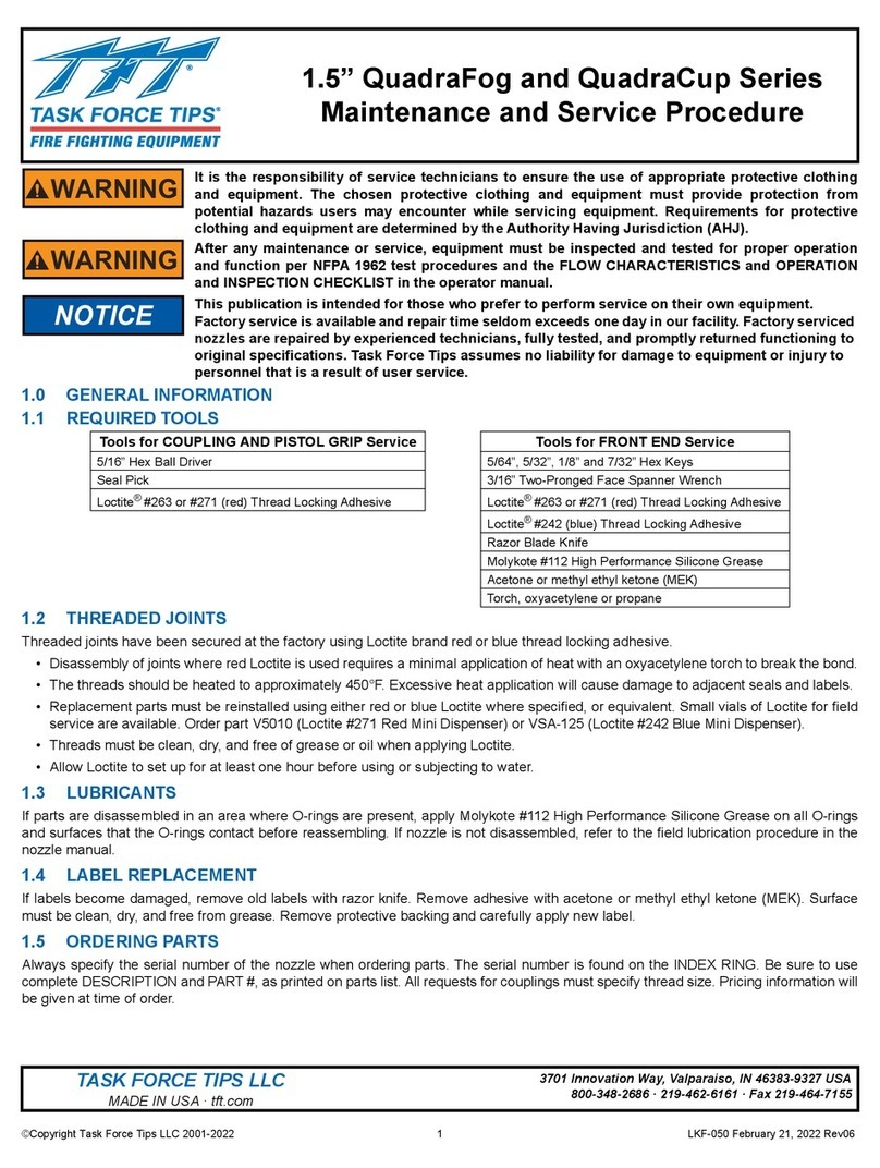
Task Force Tips 350 Series User manual

Task Force Tips

Task Force Tips 350 Series User manual

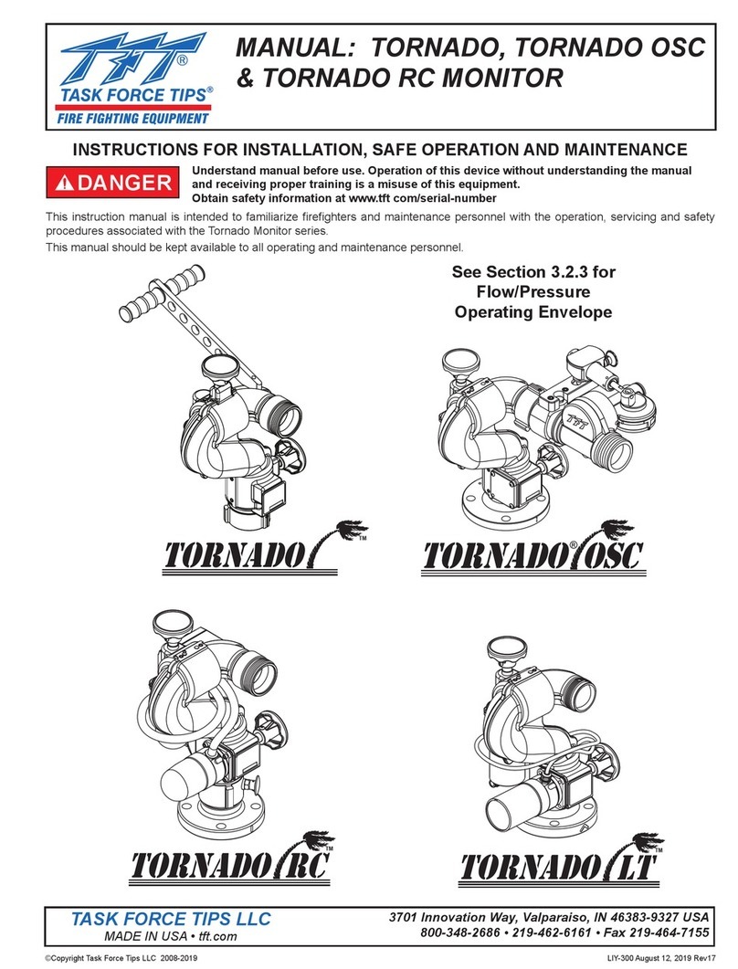
Task Force Tips TORNADO User manual

Task Force Tips

Task Force Tips TORNADO User manual

Task Force Tips Master Foam Series Programming manual

Task Force Tips

Task Force Tips Master Foam Series Programming manual

Task Force Tips Masterstream 4000 ER Automatic Quick guide

Task Force Tips

Task Force Tips Masterstream 4000 ER Automatic Quick guide

Task Force Tips Masterstream Series Programming manual

Task Force Tips

Task Force Tips Masterstream Series Programming manual

Task Force Tips Master Force Series Quick guide

Task Force Tips

Task Force Tips Master Force Series Quick guide

Task Force Tips STANDARD Quick guide

Task Force Tips

Task Force Tips STANDARD Quick guide

Task Force Tips BlitzForce Portable Monitor Programming manual

Task Force Tips

Task Force Tips BlitzForce Portable Monitor Programming manual

Task Force Tips BlitzForce XXLC-33-NH1 Programming manual

Task Force Tips

Task Force Tips BlitzForce XXLC-33-NH1 Programming manual

Task Force Tips Ultimatic Programming manual

Task Force Tips

Task Force Tips Ultimatic Programming manual

Task Force Tips BLITZTAC Portable Monitor Programming manual

Task Force Tips

Task Force Tips BLITZTAC Portable Monitor Programming manual

Task Force Tips Vortex 1.5" User manual

Task Force Tips

Task Force Tips Vortex 1.5" User manual

Task Force Tips VORTEX 2 ER User manual

Task Force Tips

Task Force Tips VORTEX 2 ER User manual

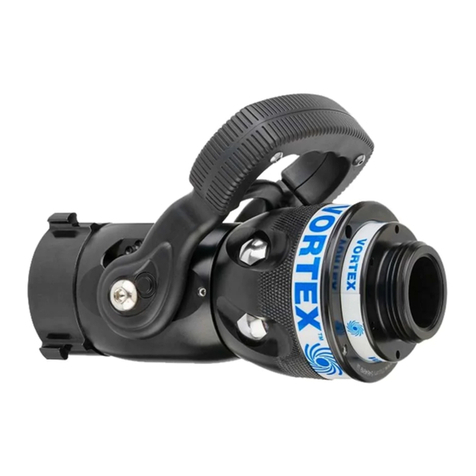
Task Force Tips QuadraFog series Manual
Task Force Tips

Task Force Tips QuadraFog series Manual

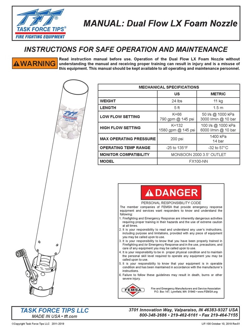
Task Force Tips FX100-NN User manual

Task Force Tips

Task Force Tips FX100-NN User manual

Task Force Tips TORNADO Programming manual

Task Force Tips

Task Force Tips TORNADO Programming manual

Task Force Tips Twister Series Installation instructions

Task Force Tips

Task Force Tips Twister Series Installation instructions

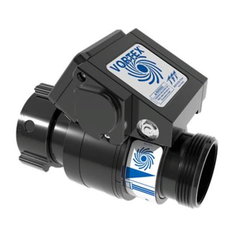
Task Force Tips Extend-A-Gun RC3 Owner's manual
Task Force Tips

Task Force Tips Extend-A-Gun RC3 Owner's manual

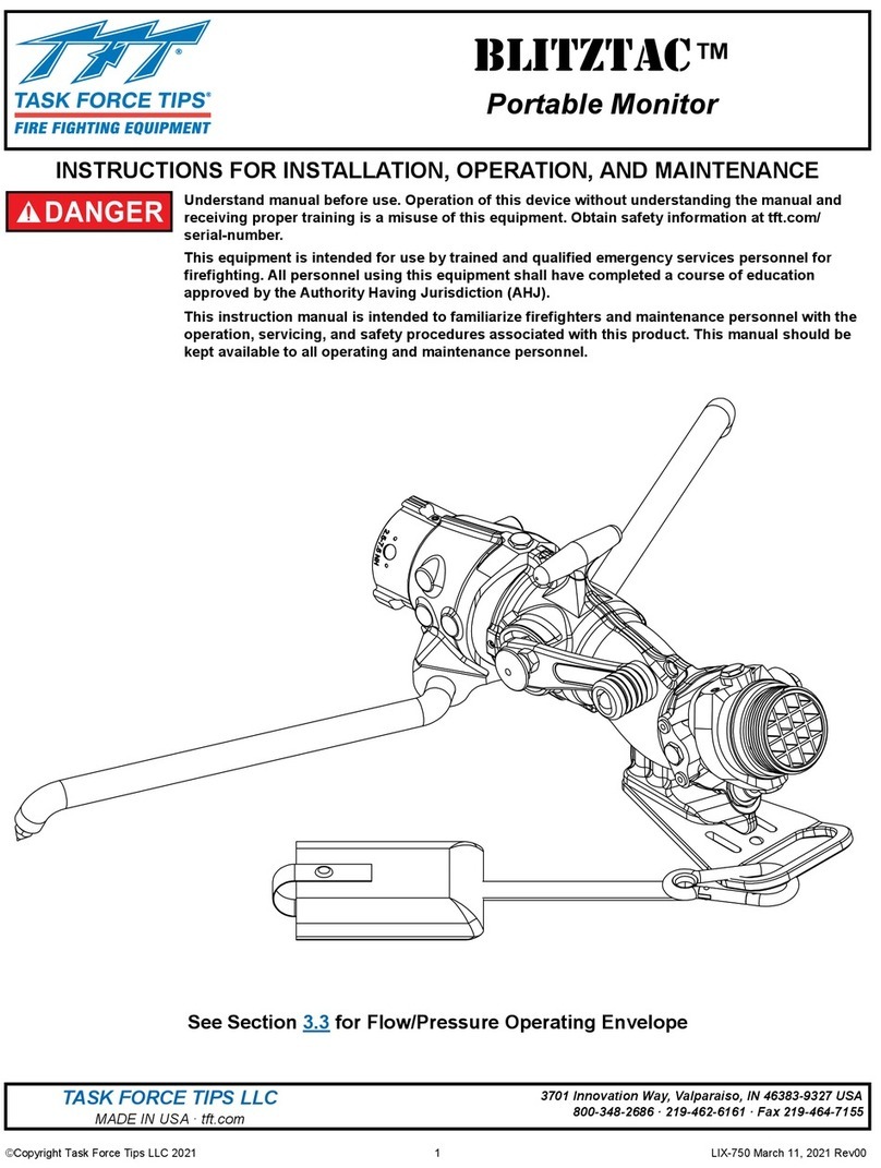
Task Force Tips EDUCTOR 125 Series Programming manual
Task Force Tips

Task Force Tips EDUCTOR 125 Series Programming manual

Popular Firefighting Equipment manuals by other brands
Tyco Fire Protection Products ANSUL CHECKFIRE 210 PLANNING, INSTALLATION, PROGRAMMING, OPERATION, AND MAINTENANCE MANUAL

Tyco Fire Protection Products

Tyco Fire Protection Products ANSUL CHECKFIRE 210 PLANNING, INSTALLATION, PROGRAMMING, OPERATION, AND MAINTENANCE MANUAL

TFT ULTIMATIC Instructions for installation, operation and maintenance

TFT

TFT ULTIMATIC Instructions for installation, operation and maintenance

Vag HYDRUS G Operation and maintenance instruction

Vag

Vag HYDRUS G Operation and maintenance instruction

Waterous 80-P Operation and maintenance instructions

Waterous

Waterous 80-P Operation and maintenance instructions

Amerex 570 Owner's service manual

Amerex

Amerex 570 Owner's service manual

SEI Industries BAMBI MAX Series Operation manual

SEI Industries

SEI Industries BAMBI MAX Series Operation manual

klimaoprema FDC manual

klimaoprema

klimaoprema FDC manual

DEVA GEPARD MAX User information

DEVA

DEVA GEPARD MAX User information

Ampac Sav-Wire 2 Base installation guide

Ampac

Ampac Sav-Wire 2 Base installation guide

Fike Sita 403-0006 Installation and maintenance instructions

Fike

Fike Sita 403-0006 Installation and maintenance instructions

Ampac 226-0003 installation guide

Ampac

Ampac 226-0003 installation guide

Enduraplas FIRE RANGER owner's manual

Enduraplas

Enduraplas FIRE RANGER owner's manual

SEI Industries 6072 Operation manual

SEI Industries

SEI Industries 6072 Operation manual

Janus FM-200 Sv Series Operation & service manual

Janus

Janus FM-200 Sv Series Operation & service manual

Fireco Dorgard SmartSound user guide

Fireco

Fireco Dorgard SmartSound user guide

Projoy Electric PEFS-24V-CN Series installation guide

Projoy Electric

Projoy Electric PEFS-24V-CN Series installation guide

manuals.online logo
manuals.online logoBrands
  • About & Mission
  • Contact us
  • Privacy Policy
  • Terms and Conditions

Copyright 2025 Manuals.Online. All Rights Reserved.