VAG Operation and Maintenance Instructions • 3
1 General
1.1 Safety
These Operation and Maintenance Instructions must
be observed and applied at all times along with the
general “VAG Installation and Operation Instructions
for Valves” (see www.vag-group.com / Category: Ins-
tallation and Operation Instructions).
Arbitrary alterations of this product and the parts supplied with it
are not allowed. VAG will not assume any liability for consequenti-
al damage due to non-compliance with these instructions.
When using this valve, the generally acknowledged rules of tech-
nology have to be observed (e.g. national standards, EN 1074-6
hydrants, fitness for purpose requirements and appropriate veri-
fication tests, etc.). The installation must only be carried out by
qualified staff (see also Section 6.1 General safety instructions).
For further technical information such as dimensions, materials or
applications, please refer to the respective documentation (KAT
1611-A).
VAG valves are designed and manufactured to the highest stan-
dardst and their safety of operation is generally ensured.. How-
ever, valves may be potentially dangerous if they are operated
improperly or are not installed for their intended use.
Everyone dealing with the assembly, disassembly, operation,
maintenance and repair of the valves must have read and under-
stood the complete Operating and Maintenance Instructions (Ac-
cident Prevention Regulations, ANSI Z535).
Before removing any protective devices and/or performing any
work on the valves, depressurise the pipeline section and ensure
it is free of hazards. Unauthorised, unintentional and unexpected
actuation as well as any hazardous movements caused by stored
energy (pressurised air, water under pressure) must be prevented.
In case of equipment that must be monitored and inspected, all
relevant laws and regulations, such as the Industrial Code, the
Accident Prevention Regulations, the Ordinance of Steam Boilers
and instructional pamphlets issued by the Pressure Vessels Study
Group must be complied with. In addition, the local accident pre-
vention regulations must be observed.
When a valve needs to be dismantled from a pipeline, fluid may
emerge from the pipeline or the valve. The pipeline must be emp-
tied completely before the valve is dismantled. Special care needs
to be taken in case of residues which may continue flowing.
1.2 Proper use
The VAG HYDRUS®G Underground Hydrant is a valve for instal-
lation in drinking water pipeline networks.
Refer to DVGW technical standard W331 for deployment and cor-
rect installation.
For the respective technical application ranges (e.g. operating
pressure, medium, temperature) please refer to the product-rela-
ted documentation (KAT 1611-A).
For any alternative operating conditions and applications, the
manufacturer’s written approval must be obtained!
These Operation and Maintenance Operation Instructions contain
important information on the safe and reliable operation of the
VAG HYDRUS®G Underground Hydrant.
Observing these Operation and Maintenance Instructions helps
you to:
•Prevent hazards
•Reduce repair costs and down-times of the valve and/or the
entire equipment
•Improve the operational safety and useful life of the equipment.
1.3 Identification
According to DIN EN 19 all valves bear an identification label spe-
cifying the nominal diameter (DN), nominal pressure (PN), body
material and the manufacturer’s logo.
After installation in the pipeline cap the following information can
been seen on the name plate when viewed from above.
VAG Manufacturer’s name
DN Nominal diameter of the valve
PN Nominal pressure of the valve
Version - flange or BAIO®plus
Installation depth (important for spare part definition)
Date of manufacture
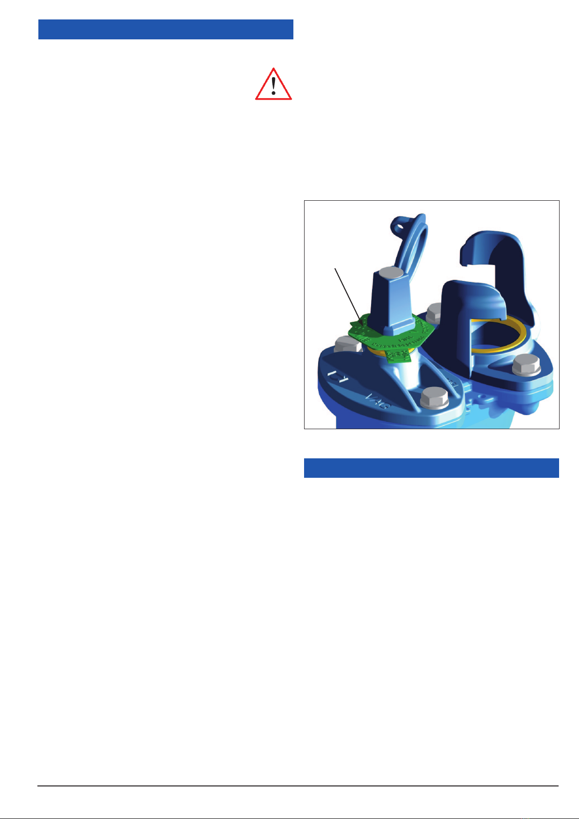
VAG name plate
Picture 1: VAG name plate
2 Transport and Storage
2.1 Transport
For transportation to its installation site, the valve must be packed
in stable packaging material suitable for the size of the valve. It
must be ensured that the valve is protected against atmospheric
influences and external damage. When the valve is shipped under
specific climatic conditions (e.g. overseas transport), it must be
specially protected and wrapped in plastic film and a desiccant
must be added.
The factory-applied corrosion protection and any assemblies
must be protected against damage by external influences during
transport and storage.
2.2 Storage
The VAG HYDRUS®G Underground Hydrant must be stored with
the opened stopper in the horizontal position.
The elastomeric parts (seals) must be protected against direct
sunlight and/or UV light otherwise their long-term sealing function
cannot be guaranteed. Store the valve in a dry and well-aerated
place and avoid direct radiator heat. The protective cover protects
functionally important components from dust and other external
impurities.
Do not remove the protective caps of the connections / flanges
and the packaging materials until immediately prior to assembly.
The valve can be stored in ambient temperatures ranging from