tau T-SKY User manual

1
T-SKY Series
MANUALE D’USO E MANUTENZIONE
USE AND MAINTENANCE MANUAL
BEDIENUNGS - UND WARTUNGSANLEITUNG
MANUEL D’EMPLOI ET D’ENTRETIEN
MANUAL DE USO Y MANTENIMIENTO
T-SKY (K690M)
Motoriduttore per porte da garage
Garage Door Opener
Garagentorantrieb
Automatisme pour Portes de Garage
Automatismo de Techo para Puertas de Garaje
Via Enrico Fermi, 43 - 36066 Sandrigo (VI) Italia
Tel +39 0444 750190 - Fax +39 0444 750376 - info@tauitalia.com - www.tauitalia.com
D-MNL0TSKY 09-10-2012 - Rev.08
IT - Istruzioni originali

2
T-SKY Series
I dati riportati nel presente manuale sono puramente indicativi. La TAU si riserva il diritto di modicarli in qualsiasi momento.
La Casa costruttrice si riserva il diritto di apportare modiche o miglioramenti al prodotto senza alcun preavviso. Eventuali imprecisioni
o errori riscontrabili nel presente fascicolo, saranno corretti nella prossima edizione.
All’apertura dell’imballo vericare che il prodotto sia integro. Riciclare i materiali secondo la normativa vigente.
L’installazione del prodotto dovrà essere effettuata da personale qualicato. La Ditta costruttrice Tau declina ogni responsabilità
per danni derivanti a cose e/o persone dovuti ad un’eventuale errata installazione dell’impianto o la non messa a Norma dello
stesso secondo le vigenti Leggi (vedi Direttiva Macchine).
I disegni esplosi presenti nelle ultime pagine delle presenti istruzioni sono puramente indicativi. Per i ricambi fare riferimento al relativo
listino.
Los datos describidos en este manual son puramente indicativos. La TAU se reserva el derecho de modicarlos en cualquier
momento.
El Fabricante se reserva el derecho de modicar o actualizar el producto sin aviso previo. Posibles imprecisiones o errores en este
manual serán corregidos en la próxima edición.
Cuando abra el embalaje, controle que el producto esté íntegro. Recicle los materiales según la normativa vigente.
La instalación del producto tiene que ser efectuada por personal cualicado. El Fabricante Tau no se asume ninguna
responsabilidad por lesiones a personas o averías a cosas causadas por una instalación incorrecta del equipo o la por la
inobservancia de la normativa vigente (véase Directiva de Máquinas).
Los dibujos estallados que hay en las ultimas paginas de este manual son puramente indicativos. Por los repuestos hay que hacer
referencia a la lista.
The data described in this handbook are purely a guide. TAU reserves the right to change them in any moment.
The manufacturer reserves the right to modify or improve products without prior notice. Any inaccuracies or errors found in this handbook
will be corrected in the next edition.
When opening the packing please check that the product is intact. Please recycle materials in compliance with current regulations.
This product may only be installed by a qualied tter. The manufacturer declines all liability for damage to property and/or
personal injury deriving from the incorrect installation of the system or its non-compliance with current law (see Machinery
Directive).
The exploded views on the last pages of this instruction manual are purely indicative. For the spare parts, please refer to the relevant
price list.
Les données décrites dans ce manual sont purement indicatives. La TAU se réserve le droit de les modier à n’importe quel moment.
Le Constructeur se réserve le droit d’apporter des modications ou des améliorations au produit sans aucun préavis. Les éventuelles
imprécisions ou erreurs présentes dans ce fascicule seront corrigées dans la prochaine édition.
À l’ouverture de l’emballage, vérier que le produit est intact. Recycler les matériaux suivant les normes en vigueur.
L’installation du produit devra être effectuée par du personnel qualié. Tau décline toute responsabilité pour les dommages
aux choses et/ou personnes dus à une éventuelle installation erronée de l’automatisme ou à la non-mise aux normes suivant
les lois en vigueur (voir Directive Machines).
Les plans “esplosi non lo so” qui se trouvent sur les dernières pages de ces notices techniques sont à titre indicatif. En ce qui concerne
les pièces détachées consulter la liste relative.
Die beschriebenen Daten in der vorliegenden Betriebsanleitung sind rein indikativ. TAU behält sich vor, diese in jedem Moment zu
modizieren.
Der Hersteller behält sich das Recht vor, ohne vorherige Benachrichtung Änderungen oder Verbesserungen am Produkt anzubringen.
Ungenauigkeiten oder Fehler, die in der vorliegenden Ausgabe festgestellt werden, werden in der nächsten Ausgabe berichtigt.
Beim Öffnen der Verpackung prüfen, dass das Produkt keine Schäden aufweist. Die Materialien nach den gültigen Vorschriften
recyclen.
Die Installation des Produktes muss von Fachpersonal ausgeführt werden. Die Herstellerrma TAU übernimmt keinerlei
Haftung für Personen- und/oder Sachschäden aufgrund einer falschen Installation der Anlage oder der Nichtkonformität
derselben mit den gültigen Gesetzen (siehe Maschinenrichtlinie).
Die explodierten Zeichnungen auf den letzten Seiten dieser Anleitung sind nur anzeigend. Für die Ersatzteile, bitte die entsprechende
Preisliste sehen.
Italiano
Español
English
Français
Deutsch

3
T-SKY Series
DATI TECNICI - TECHNICAL DATA - TECHNISCHE DATEN - DONNÉES TECHNIQUES - DATOS TÉCNICOS
TIPO - TYPE - TYP - TYPE - TIPO T-SKYKITC T-SKYKITB T-SKYKIT1C T-SKYKIT1B
Sistema di trazione - Drive system
Zug System
Système de traction
Sistema de tracción
catena - chain
Ketten
à chaîne
por cadena
cinghia - belt
Riemen
à courroie
por correa
catena - chain
Ketten
à chaîne
por cadena
cinghia - belt
Riemen
à courroie
por correa
Alimentazione - Power - Stromversorgung
Alimentation - Alimentación 230 V AC (50 ÷ 60 Hz)
Motore - Motor - Motor
Moteur - Motor 24 V DC
Corrente assorbita (a vuoto) - Absorbed current (no load)
Stromaufnahme (ohne Last) - Courant absorbé (à vide)
Corriente absorbida (en vacío)
2,2 A 2,5 A
Potenza assorbita (a vuoto) - Absorbed power (no load)
Leistungsaufnahme (ohne Last) - Puissance absorbée (à vide) -
Potencia absorbida (en vacío)
80 W 110 W
Velocità di manovra - Motor speed - Motorgeschwindigkeit
Vitesse moteur - Velocidad Motor 0,185 m/s
Grado di protezione - Protection level - Schutzart
Degré de protection - Grado de protección IP 40
Corsa utile - Useful travel - Arbeitshub - Course utile - Carrera útil 2,65 m
Ciclo di lavoro - Work cycle - Arbeitszyklus
Cycle de travail - Ciclo de trabajo 100%
Temperatura di esercizio - Operating temperature
Betriebstemperatur - Température de fonctionnement
Temperatura de funcionamiento
-20°C ÷ 55°C
Forza di trazione - Traction power - Zugkraft
Traction - Fuerza de tracción 650 N 1000 N
Radio ricevente 433,92MHz - 433,92MHz radio receiver
433,92MHz Funkempfänger - Radio récepteur 433,92MHz
Radiorreceptor 433,92MHz
incorporata - built-in
integriert - intégrée
integrado
incorporata - built-in
integriert - intégrée
integrado
Scheda carica batterie - Battery charge card
Karte Batterieladung - Carte chargeur de batterie
Tarjeta cargador de batería
incorporata - built-in
integriert - intégrée
integrada
incorporata - built-in
integriert - intégrée
integrada
NOTA: QUANDO IL SISTEMA IN 24 VDC È ALIMENTATO UNICAMENTE DALLA BATTERIA (IN CASO DI BLACK-OUT OPPURE
IN ABBINAMENTO CON PANNELLO FOTOVOLTAICO), LE PRESTAZIONI ESPRESSE DAL MOTORIDUTTORE (FORZA E
VELOCITÀ) SI RIDUCONO DEL 30% CA.
N.B. WHEN THE SYSTEM IS IN THE 24 V DC MODE AND IS POWERED BY THE BATTERY ONLY (IN THE EVENT OF A POWER
FAILURE OR WHEN USED IN CONJUNCTION WITH A PHOTOVOLTAIC PANEL), THE GEAR MOTOR’S OUTPUT (POWER AND
SPEED) IS REDUCED BY APPROXIMATELY 30% .
ANMERKUNG: WENN DAS 24 VDC SYSTEM NUR ÜBER BATTERIE GESPEIST IST (BEI STROMAUSFALL ODER IN
KOMBINATION MIT EINEM PHOTOVOLTAICPANEEL), VERRINGERN SICH DIE LEISTUNGEN DES GETRIEBEMOTORS (KRAFT
UND GESCHWINDIGKEIT) UM CA. 30%.
ATTENTION : QUAND LE SYSTÈME À 24 VCC EST ALIMENTÉ UNIQUEMENT PAR LA BATTERIE (EN CAS DE COUPURE DE
COURANT OU BIEN ENASSOCIATIONAVEC UN PANNEAU PHOTOVOLTAÏQUE), LES PERFORMANCES DU MOTORÉDUCTEUR
(FORCE ET VITESSE) DIMINUENT D’ENVIRON 30% .
NOTA: CUANDO EL SISTEMA DE 24 VDC ES ALIMENTADO ÚNICAMENTE POR LA BATERÍA (EN CASO DE CORTE DE
CORRIENTE, O BIEN COMBINADO CON PANEL FOTOVOLTAICO), LAS PRESTACIONES DEL MOTORREDUCTOR (FUERZA Y
VELOCIDAD) SE REDUCEN EN UN 30%.

4
T-SKY Series
1_ AVVERTENZE PER L’INSTALLATORE
OBBLIGHI GENERALI PER LA SICUREZZA
1) Leggere attentamente le istruzioni prima di procedere
all’installazione, in quanto forniscono importanti indica-
zioni concernenti la sicurezza, l’installazione, l’uso e la
manutenzione. Una errata installazione o un errato uso
del prodotto può portare a gravi danni alle persone.
2) I materiali dell’imballaggio (plastica, polistirolo, ecc.) non de-
vono essere lasciati alla portata dei bambini in quanto poten-
ziali fonti di pericolo.
3) Conservare le istruzioni per riferimenti futuri.
4) Questo prodotto è stato progettato e costruito esclusivamen-
te per l’utilizzo indicato in questa documentazione. Qualsiasi
altro utilizzo non espressamente indicato potrebbe pregiudi-
care l’integrità del prodotto e/o rappresentare fonte di perico-
lo.
5) TAU declina qualsiasi responsabilità derivata dall’uso impro-
prio o diverso da quello per cui l’automatismo è destinato.
6) Non installare il prodotto in ambiente e atmosfera esplosivi.
7) Gli elementi costruttivi meccanici devono essere in accordo
con quanto stabilito dalle Norme EN 12604 e EN 12605. Per
i Paesi extra-CEE, oltre ai riferimenti normativi nazionali, per
ottenere un livello di sicurezza adeguato, devono essere se-
guite le Norme sopra riportate.
8) TAU non è responsabile dell’inosservanza della Buona Tec-
nica nella costruzione delle chiusure da motorizzare, nonché
delle deformazioni che dovessero intervenire nell’utilizzo.
9) Considerando i pericoli che si possono vericare durante
l’installazione e l’uso di T-SKY, per la massima sicurezza è
necessario che l’installazione avvenga nel pieno rispetto di
leggi, norme e regolamenti. In questo capitolo verranno ripor-
tate avvertenze di tipo generico; altre importanti avvertenze
sono presenti nei capitoli “Veriche preliminari” e “Messa in
servizio”.
Secondo la più recente legislazione europea, la rea-
lizzazione di una porta o cancello automatico ricade
in quanto previsto dalla Direttiva 98/37/CE (Direttiva
Macchine) e nel particolare, alle norme: EN 12445; EN
12453 ed EN 12635, che consentono di dichiarare la
presunzione di conformità.
10) Prima di iniziare l’installazione è necessario eseguire analisi
dei rischi che comprendente l’elenco dei requisiti essenziali
di sicurezza previsti nell’allegato I della Direttiva Macchine,
indicando le relative soluzioni adottate. Si ricorda che l’analisi
dei rischi è uno dei documenti che costituiscono il “Fascicolo
tecnico” dell’automazione.
11) Vericare la necessità di ulteriori dispositivi per completare
l’automazione con T-SKY in base alla specica situazione
d’impiego ed ai pericoli presenti; devono essere considerati
ad esempio i rischi di impatto, schiacciamento, cesoiamento,
convogliamento, ecc., ed altri pericoli in genere.
12) L’installazione deve essere effettuata nell’osservanza delle
Norme EN 12453 e EN 12445. Per i Paesi extra-CEE, oltre
ai riferimenti normativi nazionali, per ottenere un livello di si-
curezza adeguato, devono essere seguite le Norme sopra
riportate.
13) Prima di effettuare qualsiasi intervento sull’impianto, togliere
l’alimentazione elettrica e scollegare le batterie.
14) Prevedere sulla rete di alimentazione dell’automazione un
interruttore onnipolare con distanza d’apertura dei contatti
uguale o superiore a 3 mm. È consigliabile l’uso di un ma-
gnetotermico da 6A con interruzione onnipolare.
15) Vericare che a monte dell’impianto vi sia un interruttore dif-
ferenziale con soglia da 0,03 A.
16) Vericare che l’impianto di terra sia realizzato a regola d’arte
e collegarvi le parti metalliche della chiusura.
17) I dispositivi di sicurezza (norma EN 12978) permettono di
proteggere eventuali aree di pericolo da Rischi meccanici di
movimento, come ad es. schiacciamento, convogliamento,
cesoiamento.
18) Per ogni impianto è consigliato l’utilizzo di almeno una se-
gnalazione luminosa nonché di un cartello di segnalazione
ssato adeguatamente sulla struttura dell’insso, oltre ai di-
spositivi citati al punto 18.
19) TAU declina ogni responsabilità ai ni della sicurezza e del
buon funzionamento dell’automazione in caso vengano utiliz-
zati componenti dell’impianto non di produzione TAU.
20) Per la manutenzione utilizzare esclusivamente parti originali
TAU.
21) Non eseguire alcuna modica sui componenti facenti parte
del sistema d’automazione.
22) L’automatismo non può essere utilizzato prima di aver effet-
tuato la messa in servizio come specicato nel capitolo:“5
Collaudo e messa in servizio”.
23) L’installatore deve fornire tutte le informazioni relative al
funzionamento manuale del sistema in caso di emergenza
e consegnare all’Utente utilizzatore dell’impianto la “Guida
Utente” allegata al prodotto.
24) Non permettere ai bambini o persone di sostare nelle vicinan-
ze del prodotto durante il funzionamento.
25) Tenere fuori dalla portata dei bambini radiocomandi o qual-
siasi altro datore di impulso, per evitare che l’automazione
possa essere azionata involontariamente.
26) Il transito sotto la porta deve avvenire solo ad automazione
ferma.
27) L’Utente utilizzatore deve astenersi da qualsiasi tentativo di
riparazione o d’intervento diretto e rivolgersi solo a personale
qualicato.
28) Prima di accedere ai morsetti interni al coperchio di T-SKY
scollegare tutti i circuiti di alimentazione; se il dispositivo di
sconnessione non è a vista apporvi un cartello:“ATTENZIONE
MANUTENZIONE IN CORSO”.
29) Manutenzione: effettuare almeno semestralmente la verica
funzionale dell’impianto, con particolare attenzione all’ef-
cienza dei dispositivi di sicurezza (compresa, ove previsto, la
forza di spinta dell’operatore) e di sblocco.
30) Tutto quello che non è previsto espressamente in queste
istruzioni non è permesso.
Consigliamo di riporre tutta la documentazione relativa all’im-
pianto all’interno o nelle immediate vicinanze della centrali-
na.
2_ DESCRIZIONE PRODOTTO E DESTINAZIONE
D’USO (g. 1)
T-SKY è una linea di motoriduttori destinati all’automazione di por-
te sezionali e, con l’apposito accessorio P-100BANT non fornito,
portoni basculanti a molle o a contrappesi, sia debordanti che non.
T-SKY viene fornito in due soluzioni, con la guida di scorrimento a
binario unico (L= 3m - gli organi di movimento sono già assemblati
in fabbrica) oppure nella versione a 3 pezzi da montare (gli organi
di movimento devono essere montati dall’installatore).
Il sistema irreversibile garantisce il blocco meccanico della porta
quando il motore non è in funzione e quindi non occorre installa-
re alcuna serratura; uno sblocco manuale interno ed uno esterno
(opzionale) rendono manovrabile la porta in caso di mancanza di
alimentazione o disservizio.
È possibile utilizzare l’accessorio batteria tampone P-200BATT-
SKY (opzionale) che permette alcune manovre anche in assenza
di alimentazione da rete.
L’automazione T-SKY è stata progettata e costruita per
uso interno e per controllare l’accesso veicolare. Evita-
re qualsiasi altro utilizzo.
1_ Base
2_ Coperchio
3_ Sportello
4_ Centrale di comando
5_ Lampada di cortesia
6_ Gruppo di rinvio
7_ Guida di scorrimento
8_ Carrello di trascinamento
9_ Staffa attacco porta
10_ Attacco anteriore
11_ Tendicatena
12_ Attacco posteriore
13_ Pomello di sblocco
ITALIANO
5
T-SKY Series
ITALIANO
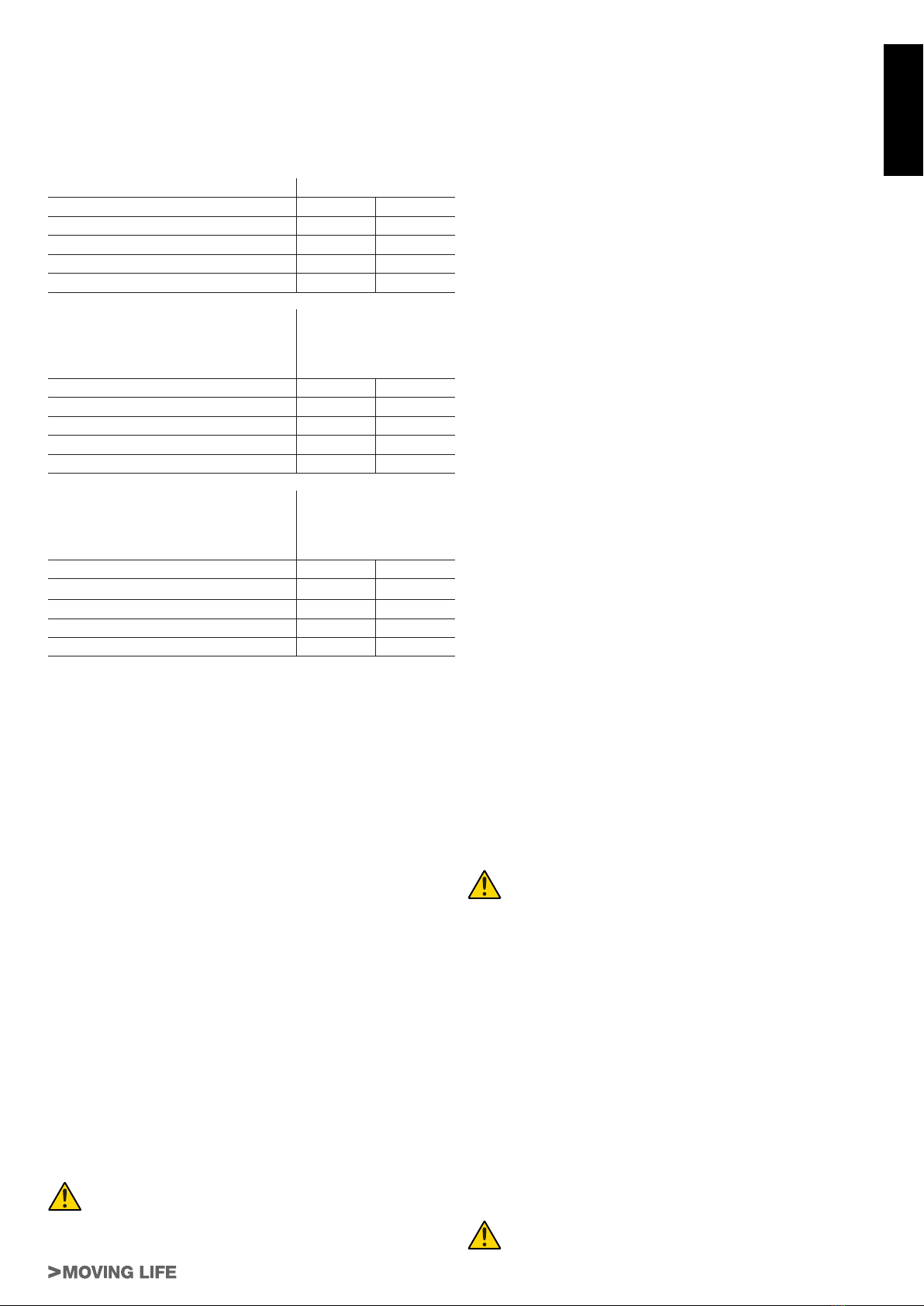
2.1_ Limiti d’impiego e dimensioni (g. 2)
I dati relativi alle prestazioni dei prodotti della linea T-SKY sono
riportati nella tabella “Dati tecnici” e sono gli unici valori che con-
sentono la corretta valutazione all’uso.
Le caratteristiche strutturali dei prodotti T-SKY li rendono atti all’uso
su portoni di tipo sezionale o basculante, secondo i limiti riportati
in tabella
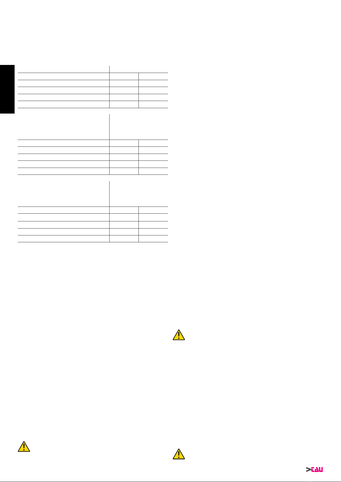
Modello Portone SEZIONALE
Altezza Larghezza
T-SKY (guida P-100BINBELT/CHAIN) 2,5m 3,5m
T-SKY (guida
P-100BINBELT3/CHAIN3
) 2,5m 3,5m
T-SKY1 (guida P-100BINBELT/CHAIN) 2,5m 5m
T-SKY1 (guida
P-100BINBELT3/CHAIN3
) 2,5m 5m
Modello Portone BASCULANTE
non debordante
(con accessorio
P-100BANT)
Altezza Larghezza
T-SKY (guida P-100BINBELT/CHAIN) 2,2m 3m
T-SKY (guida
P-100BINBELT3/CHAIN3
)2,2m 3m
T-SKY1 (guida P-100BINBELT/CHAIN) 2,2m 4m
T-SKY1 (guida
P-100BINBELT3/CHAIN3
)2,2m 4m
Modello Portone BASCULANTE
debordante
(con accessorio
P-100BANT)
Altezza Larghezza
T-SKY (guida P-100BINBELT/CHAIN) 2,8m 3m
T-SKY (guida
P-100BINBELT3/CHAIN3
)2,8m 3m
T-SKY1 (guida P-100BINBELT/CHAIN) 2,8m 4m
T-SKY1 (guida
P-100BINBELT3/CHAIN3
)2,8m 4m
Nota: utilizzando l’art. P-100PROC o (P-100PROB) le altezze ri-
portate nelle tabelle possono essere aumentate di 1m.
Le misure riportate nelle tabelle sono puramente indicative e ser-
vono per una stima di massima. La reale idoneità di T-SKY ad au-
tomatizzare un determinato portone dipende dal grado di bilancia-
mento dell’anta; dagli attriti delle guide e da altri fenomeni, anche
occasionali, come la pressione del vento o la presenza di ghiaccio
che potrebbero ostacolare il movimento dell’anta.
2.2_ Impianto tipo e sezione cavi (gg. 3-4-5)
1_ Motoriduttore con centrale di comando
2_ Fotocellule
3_ Fotocellule su colonnina
4_ Bordo sensibile
5_ Lampeggiante ed antenna
6_ Selettore a chiave
7_ Pulsantiera
8_ Sblocco esterno (opzionale)
a_ 4x0,5 mm²
b_ 2x0,5 mm² + RG58
c_ 2x0,5 mm²
d_ 3x0,5 mm²
e_ 3x0,5 mm²
f_ 4x0,5 mm²
3_ INSTALLAZIONE
L’installazione di T-SKY deve essere effettuata da per-
sonale qualicato, nel rispetto di leggi, norme e regola-
menti e di quanto riportato nelle presenti istruzioni.
3.1_ Veriche preliminari
Prima di procedere con l’installazione di T-SKY è necessario ese-
guire questi controlli:
• Vericare che tutto il materiale da utilizzare sia in ottimo stato,
adatto all’uso e conforme alle norme.
• Vericare che la struttura del portone sia adatta ad essere au-
tomatizzata.
• Vericare che il portone abbia forza e dimensioni che rientrino
nei limiti di impiego riportati nel paragrafo 2.1.
• Vericare che la porta sia conforme alle normative EN12604 e
EN12605.
• La porta, durante il movimento, non deve invadere aree pubbli-
che preposte al transito pedonale o veicolare.
• Vericare che nella corsa del portone, sia in chiusura che in
apertura, non ci siano punti di maggiore attrito.
• Vericare la robustezza degli arresti meccanici e controllare
che non vi sia pericolo di uscita dalle guide del portone.
• Vericare che il portone sia ben bilanciato, cioè non deve muo-
versi se lasciato fermo in una qualsiasi posizione.
• Vericare che i punti di ssaggio dei vari dispositivi (fotocellule,
pulsanti, ecc…) siano in zone protette da urti e le superci di
ssaggio siano sufcientemente solide.
• Vericare che vi siano gli spazi minimi e massimi riportati nelle
gure 6 e 7.
• Evitare che le parti dell’automatismo possano venir immerse in
acqua o in altre sostanze liquide.
• Non tenere i componenti di T-SKY vicino a fonti di calore né
esporlo a amme; tali azioni possono danneggiarlo ed essere
causa di malfunzionamenti, incendio o situazioni di pericolo.
• Nel caso sia presente un porta di passaggio interna al portone,
assicurarsi che non intralci la normale corsa, e nel caso prov-
vedere con un sistema di interblocco opportuno.
• Se il portone da automatizzare è di tipo basculante, vericare
la quota A di gura 8, cioè la distanza minima tra il lato superio-
re della guida ed il punto massimo raggiunto dal bordo superio-
re del portone. Altrimenti T-SKY non può essere montato.
• Collegare la spina di alimentazione di T-SKY ad una presa elet-
trica dotata di messa a terra di sicurezza.
• La presa elettrica deve essere protetta da un adeguato dispo-
sitivo magnetotermico e differenziale.
3.2_ Assemblaggio guida di scorrimento
Se si dispone della guida di scorrimento in tre pezzi occorre ese-
guirne l’assemblaggio, procedendo come di seguito riportato:
1_ Raddrizzare i tre binari dopo aver inlato la staffa a farfalla sul
secondo spezzone (per il ssaggio al softto), come da g. 9.
2_ Scorrere il giunto in maniera da unire i binari (g. 10) e ssarlo
per mezzo della vite (B g 10) in dotazione.
3_ Regolare la tensione della catena/cinghia agendo sul dado del
tendicatena (A g. 10) no a sentirla sufcientemente rigida.
Se, invece, si dispone della guida già assemblata, tendere la cate-
na/cinghia no a sentirla sufcientemente rigida.
Se la catena/cinghia viene tesa eccessivamente, il
motore lavora sotto sforzo con conseguente aumento
dell’assorbimento di corrente.
Nel caso la porta da motorizzare abbia un’altezza maggiore di 2,5
m, sarà necessario utilizzare l’accessorio opzionale 100PROC
(per trazione a catena) o 100PROB (per trazione a cinghia) per
prolungare la guida di scorrimento di 1 m. Per l’assemblaggio, pro-
cedere come segue:
• guida 100BINCHAIN3 - trazione a catena (100PROC)
1_ Inlare lo spezzone aggiuntivo da 1 m all’interno del proprio
giunto da 700 mm (g. 11).
2_ Tenere sbloccato il carrello di trascinamento (A g. 12) e fare
scorrere la catena no a far fuoriuscire il giunto (B g. 12).
3_ Aggiungere lo spezzone in dotazione alla catena (g. 13).
4_ Scorrere la catena no a bloccarla sul carrello di trascina-
mento (g. 14).
5_ Inserire lo spezzone aggiuntivo del carter (con il proprio giun-
to) ed unire i quattro binari come detto precedentemente
(gg. 9-10).
6_ Tendere la catena per mezzo del dado (A g. 15) no a sen-
tirla sufcientemente rigida.
Se la catena/cinghia viene tesa eccessivamente, il
motore lavora sotto sforzo con conseguente aumento
dell’assorbimento di corrente.

6
T-SKY Series
• guida 100BINCHAIN - trazione a catena (100PROC)
1_ Inlare lo spezzone aggiuntivo da 1 m all’interno del proprio
giunto da 700 mm (g. 11).
2_ Allentare la tensione della catena per mezzo del dado (A g.
15) e rimuovere il tendicatena.
3_ Tenere sbloccato il carrello di trascinamento (A g. 12) e fare
scorrere la catena no a far fuoriuscire il giunto (B g. 12).
4_ Aggiungere lo spezzone in dotazione alla catena (g. 13).
5_ Scorrere la catena no a bloccarla sul carrello di trascina-
mento (g. 14).
6_ Inserire lo spezzone aggiuntivo del carter (con il proprio giun-
to) ed unirlo al binario lungo (g. 16).
7_ Montare il tendicatena e regolare la tensione della catena
no a sentirla sufcientemente rigida.
Se la catena/cinghia viene tesa eccessivamente, il
motore lavora sotto sforzo con conseguente aumento
dell’assorbimento di corrente.
• guida 100BINBELT3 e 100BINBELT - trazione a cinghia
(100PROB)
Se si dispone del binario in tre pezzi, è necessario innanzitutto as-
semblarlo come riportato all’inizio del paragrafo; successivamente,
le operazioni sono le stesse per entrambe le versioni:
1_ Inlare lo spezzone aggiuntivo da 1 m all’interno del proprio
giunto da 700 mm (g. 11).
2_ Allentare la tensione della cinghia per mezzo del dado (A g.
17).
3_ Tenere sbloccato il carrello di trascinamento (A g. 18) e fare
scorrere la cinghia no a far fuoriuscire il giunto (B g. 18).
4_ Dopo aver rimosso le viti che la tengono bloccata, estrarre la
cinghia e rimuoverla dalla guida di scorrimento (g. 19).
5_ Rimuovere l’attacco posteriore, come in gura 20. Questa
operazione richiede una certa forza, eventualmente utilizzare
un martello in gomma.
6_ Unire la prolunga di 1 m al binario con il proprio giunto (g.
21).
7_ Passare un’estremità della cinghia attraverso la testata,
come in g. 22, e ssarla al giunto con le viti e le rondelle già
presenti (g. 23). Fate attenzione alla posizione della cinghia:
deve essere con i denti rivolti verso l’interno, dritta e senza
attorcigliamenti.
8_ Assemblare il gruppo di rinvio come in gura 24. Questa ope-
razione richiede una certa forza, eventualmente utilizzare un
martello in gomma.
9_ Passare l’estremità libera della cinghia attraverso il carrello,
al rinvio del tendicinghia e quindi di nuovo attraverso il car-
rello no ad arrivare al giunto in modo da determinarne la
lunghezza. Fate attenzione alla posizione della cinghia: deve
essere con i denti rivolti verso l’interno, dritta e senza attorci-
gliamenti.
10_ Tagliare la cinghia alla lunghezza appena denita e ssarla al
giunto con le viti e le rondelle già presenti (A g. 25).
11_ Scorrere la cinghia no a bloccarla sul carrello di trascina-
mento (B g. 25).
12_ Tendere la cinghia per mezzo del dado (A g. 26) no a sen-
tirla sufcientemente rigida.
Se la catena/cinghia viene tesa eccessivamente, il
motore lavora sotto sforzo con conseguente aumento
dell’assorbimento di corrente.
3.3_ Fissaggio del motoriduttore alla guida
1_ Unire il motoriduttore con la testa della guida; quindi ssarlo
tramite le 4 viti in dotazione, come in gura 27.
2_ Il motore può essere ruotato in tre diverse posizioni, come in
gura 6.
3.4_ Fissaggio del motoriduttore al softto
1_ Rispettando le quote A, B di gura 6, tracciare al centro del
portone i due punti di ssaggio della staffa anteriore della gui-
da. In base al tipo di materiale, la staffa anteriore può essere
ssata con rivetti, tasselli o viti.
2_ Dopo avere forato nei punti previsti, lasciando il motoriduttore
a terra, sollevare la guida dalla parte anteriore e ssarla con
due viti, tasselli o rivetti a seconda della supercie.
3_ Sollevare la guida di scorrimento no a portare l’attacco po-
steriore al medesimo livello di quello anteriore oppure no a
raggiungere la medesima inclinazione del binario orizzontale
della porta (A g. 28).
4_ Misurare la distanza tra il softto e l’interasse dei fori di s-
saggio del gruppo di rinvio (B g. 28).
5_ Piegare alla misura rilevata le staffe in dotazione (effettuare
la misura a partire dal centro della prima asola della staffa).
6_ Montare le staffe sul gruppo di rinvio e riposizionare la guida
di scorrimento (g. 29).
7_ Segnare i punti di ssaggio a softto dell’attacco posteriore e
forare (avendo cura di proteggere la guida di scorrimento).
Terminare l’installazione della guida.
8_ Se si dispone della guida in 3 pezzi, ripetere le operazioni dal
punto 4 al punto 7 per il ssaggio a metà binario.
9_ Per sezionali particolarmente pesanti o che lavorano in con-
dizioni non ottimali, è disponibile l’accessorio opzionale P-
100BINSUPP per un secondo ssaggio al softto (g. 3).
10_ Assemblare la staffa per l’attacco alla porta come da g. 30.
11_ Con il portone chiuso tirare la cordicella per sganciare il car-
rello, come in gura 31.
12_ Fare scorrere il carrello no a portare la staffa di attacco anta
sul bordo superiore del portone, esattamente perpendicolare
alla guida. Fissare poi la staffa attacco anta con rivetti o viti,
come in gura 32. Utilizzare viti o rivetti adeguati al materiale
dell’anta vericando che siano in grado di supportare tutto lo
sforzo necessario all’apertura e chiusura dell’anta stessa.
13_ Allentare le viti del fermo meccanico di chiusura, quindi spo-
starlo davanti al carrello, come in gura 33. Spingere quest’ul-
timo con forza nella direzione di chiusura e, nella posizione
raggiunta, stringere con forza le viti (A).
14_ Per la fase di apertura sfruttare il primo fermo meccanico di-
sponibile, sia esso quello proprio della porta o, in alternativa,
l’intero binario dell’automazione.
15_ Provare a muovere manualmente il portone. Vericare che
il carrello scorra facilmente, senza attriti sulla guida e che la
manovra manuale sia agevole senza richiedere sforzi parti-
colari.
3.5_ Installazione dei vari dispositivi
Effettuare l’installazione degli altri dispositivi previsti seguendo le
rispettive istruzioni. Vericare in gura 2 i dispositivi che possono
essere collegati a T-SKY.
3.6_ Accessori opzionali
La gamma dei motori della serie T-SKY è completata dai seguenti
accessori opzionali:
• P-100BANT adattatore per porte basculanti;
• P-150SETSKY sblocco manuale esterno da applicare alla ma-
niglia;
• P-750BATTSKY Battery Pack;
• P-100BINSUPP Kit ssagio supplementare binario;
• P-100PROC Prolunga per T-SKY;
• P-100PROB Prolunga per T-SKY;
• 100BANT (g. 34)
Adattatore per porte basculanti.
Il 100BANT deve essere usato per motorizzare porte basculanti a
contrappesi con motorizzazioni mod. T-SKY e T-SKY1.
• 150SETSKY
Sblocco esterno (vedi istruzioni relative).
• 750BATTSKY
Kit batterie (vedi istruzioni relative).
• 100BINSUPP (g. 3)
Kit ssagio supplementare binario.
• 100PROC (g. 9 - 14)
Prolunga per T-SKY a catena.
• 100PROB (g. 17 - 26)
Prolunga per T-SKY a cinghia.
ITALIANO
7
T-SKY Series
ITALIANO
3.7_ Collegamenti elettrici
Tutti i collegamenti elettrici devono essere eseguiti in
assenza di tensione all’impianto.
1_ Per aprire il coperchio di protezione ed accedere alla centrale
elettronica di controllo di T-SKY occorre premere sul lato del
coperchio e far ruotare lo sportello come in g. 35.
2_ Far passare attraverso i passacavi i cavi di collegamento ver-
so i vari dispositivi, lasciandoli 20÷30cm più lunghi del ne-
cessario. Vedere par. 2.2 per il tipo di cavi e la gura 3 per i
collegamenti.
3_ Eseguire i collegamenti dei cavi secondo lo schema di gura
36. Per maggiore comodità, i morsetti sono estraibili.
3.8_ Allacciamento dell’alimentazione
Per l’alimentazione elettrica a T-SKY è sufciente collegare la linea
230 Vac al porta fusibile di protezione del trasformatore (A g. 36).
L’allacciamento dell’alimentazione a T-SKY deve esse-
re eseguito da personale esperto, qualicato, in pos-
sesso dei requisiti richiesti e nel pieno rispetto di leggi,
norme e regolamenti.
La linea elettrica di alimentazione deve essere protetta
contro il corto circuito e le dispersioni a terra; deve es-
sere presente un dispositivo che permetta di staccare
l’alimentazione durante l’installazione o la manutenzio-
ne di T-SKY.
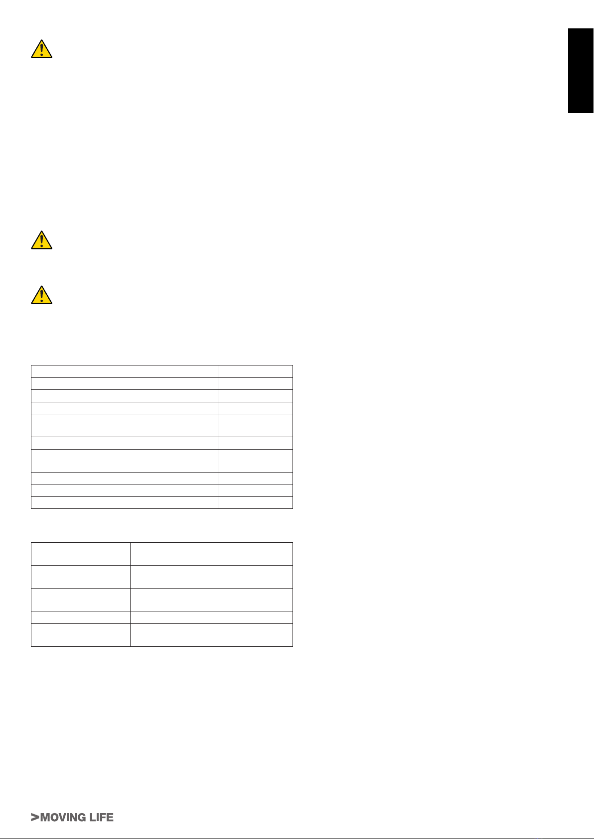
4_ SCHEDA ELETTRONICA K690M
4.1_ Caratteristiche tecniche
Alimentazione scheda 24 Vac - 50 Hz
Potenza max. motore c.c. 50 W - 24 Vdc
Fusibile rapido protezione motore (F1 - 5x20) F 10 A
Fusibile rapido protezione batteria (F2 - 5x20) F 10 A
Fusibile rapido protezione ausiliari 24 V dc (F3
- 5x20) F 2 A
Tensione circuiti alimentazione motore 24 Vdc
Tensione alimentazione circuiti dispositivi au-
siliari 24 Vdc
Tensioni alimentazioni circuiti logici 5 Vdc
Temperatura di funzionamento -20 °C ÷ +70 °C
Grado di protezione del contenitore IP 30
4.2_ Led di diagnosi
DL1 (OPEN/CLOSE) led rosso di segnalazione pulsante
APRE/CHIUDE
DL2 (STOP) led verde di segnalazione pulsante
STOP
DL4 (PHOTO) led verde di segnalazione FOTOCEL-
LULA
DL3 (ERR) led rosso di segnalazione ERRORI
DL5 (POWER) led verde di segnalazione
PRESENZA
RETE (anche tensione batteria)
4.3_ Collegamenti alla morsettiera
FS1 - FS2 ingresso alimentazione scheda 24 Vac - Alimentato
dal trasformatore riposto nell’apposito vano del mo-
tore T-SKY e protetto da fusibile sull’alimentazione
230 Vac.
1-4 (Photocell) ingresso FOTOCELLULE O DISPOSITIVI DI
SICUREZZA attivi in chiusura (contatto Normalmente Chiu-
so); il loro intervento, in fase di chiusura provoca l’arresto
seguito dalla totale riapertura della porta, in fase di apertura
provoca la fermata temporanea dela porta no a rimozione
dell’ostacolo rilevato (solo se programmato dip switch nr.
3 in ON). Nel caso di più dispositivi di sicurezza, collegare
tutti i contatti NC IN SERIE. 1= FOTOCELLULA.
N.B. Il trasmettittore della fotocellula deve sempre essere
alimentato dai morsetti nr 5 - 6, in quanto su di esso si
effettua la verica del sistema di sicurezza (Fototest).
Per eliminare la verica del sistema di sicurezza, o
quando non si usano le fotocellule, porre il dip-switch
nr 6 in OFF. Se il fototest non va a buon ne, la centra-
lina non funziona.
2-4 (Stop) ingresso pulsante STOP (contatto Normalmente
Chiuso); Arresta la porta dovunque si trovi, inibendo tem-
poraneamente la chiusura automatica, se programmata.
Ripartirà di nuovo schiacciando il pulsante APRE/CHIUDEo
il radiocomando. 2= STOP, 4= COMUNE.
3-4 (Open/Close) ingresso pulsante APRE/CHIUDE (contat-
to Normalmente Aperto); Comanda l’apertura e la chiu-
sura della porta ed è regolato nel funzionamento dai dip-
switches 2 e 4. 3= APRE/CHIUDE.
5-6 (Photocell TX) uscita 24 Vdc, per l’ALIMENTAZIONE DEL
TX DELLE FOTOCELLULE (solo quello che effettua il Fo-
totest) max. nr. 1 trasmettitore fotocellule.
5= NEGATIVO, 6= POSITIVO.
6-7 (Photocell RX) uscita 24 Vdc, max. 15 W, per l’ALIMEN-
TAZIONE DELLE RX ED EVENTUALI ALTRI TX DELLE
FOTOCELLULE, RICEVITORI ESTERNI, etc; collegare
max. n° 3 coppie di fotocellule. 6= POSiTIVO, 7= NEGATI-
VO.
8-9 (Flashing light) uscita LAMPEGGIANTE 24 Vdc, max. 15
W. Il segnale fornito è già opportunamente modulato per
l’uso diretto. La frequenza di lampeggio è doppia in fase di
chiusura. 8= POSITIVO, 9= NEGATIVO.
10-11 (Antena) Ingresso ANTENNA per RX 433,92 MHz incorpo-
rata. 10= MASSA, 11= SEGNALE.
M4 innesto rapido per connessione ENCODER e MOTO-
RE. Marrone= 5 Vcc (+5V), verde= SEGNALE ENCO-
DER (ENC), Bianco= 0 Vcc (GND), nero= NEGATIVO
MOTORE, rosso= POSITIVO MOTORE.
17 - 18 ingresso BATTERIE 24V - 1,2Ah.
4.4_ Procedura di memorizzazione
ATTENZIONE: Dopo aver alimentato il quadro di comando at-
tendere 2 sec. prima di iniziare a svolgere le manovre di rego-
lazione.
Terminata l’installazione dell’automazione:
1_ portare la porta a 1 m ca. dalla battuta in chiusura;
2_ posizionare il dip-switch nr. 10 in ON;
3_ comandare l’automazione agendo su uno dei seguenti ingres-
si: A/C, radiocomando o pulsante scheda (O/C).
4_ la porta deve cominciare a chiudere.
N.B.: nel caso dovesse aprirsi, sospendere la programma-
zione resettando il quadro elettrico (togliere l’alimen-
tazione al quadro per almeno 5 sec. e rimettere il dip-
switch nr. 10 in OFF), e quindi a quadro disalimentato
invertire tra di loro i li di alimentazione del motore.
Riprendere poi la procedura dal punto 1.
5_ effettuata la chiusura, trascorso un tempo di circa 2 sec., vie-
ne eseguita automaticamente un’apertura totale e una nuova
chiusura;
6_ a chiusura completata, attendere che il led DL3 sia acceso s-
so, quindi posizionare il dip-switch nr. 10 in OFF;
7_ l’automazione è ora pronta per il funzionamento.
Effettuare le regolazioni logiche.
N.B.: agendo su qualsiasi regolazione del quadro di coman-
do (trimmer o dip-switches) è necessario effettuare una
manovra completa (apertura e chiusura) dell’automa-
zione per rendere attive le nuove impostazioni.
4.5_ Regolazioni logiche
TRIMMER
T.C.A. Trimmer di regolazione del tempo di chiusura automati-
ca. Da 0 a 120 sec.
Ruotando in senso orario si aumenta la spinta.

8
T-SKY Series
FRA Trimmer di regolazione della forza durante la fase di
apertura.
Ruotando in senso orario si aumenta la spinta.
FRC Trimmer di regolazione della forza durante la fase di
chiusura.
Ruotando in senso orario si aumenta la spinta.
TRM4 }vedi menù tecnico dip-switch 7-8.TRM5
TRM6
4.6_ Dip-switch
1 on: ad apertura completata, la chiusura della porta è automati-
ca trascorso un tempo impostato sul trimmer T.C.A.;
off: la chiusura necessita di un comando manuale;
2 on: ad automazione funzionante, una sequenza di comandi di
apertura/chiusura induce la porta ad una APERTURA-CHIU-
SURA-APERTURA-CHIUSURA, etc. (vedi anche dip switch 4);
off: nelle stesse condizioni, la stessa sequenza di comandi di
apertura/chiusura induce la porta ad una APERTURA-STOP-
CHIUSURA-STOP-APERTURA-STOP, etc. (funzione passo-
passo);
3on: durante la fase di apertura la fotocellula interviene arre-
stando la porta no a rimozione dell’ostacolo rilevato. Alla rimo-
zione dell’ostacolo la porta riprende l’apertura;
off: durante la fase di apertura la fotocellula non interviene;
4on: funzione NO-REVERSE attiva; la porta ignora i comandi
di chiusura durante l’apertura e l’inversione di marcia avviene
solo in fase di chiusura;
off: azionando il pulsante apre-chiude avremo una inversione
di marcia anche in fase di apertura;
5 on: la funzione prelampeggio è abilitata;
off: la funzione prelampeggio è disabilitata;
6 on: la funzione “verica delle fotocellule” è inserita;
off: la funzione “verica delle fotocellule” è disinserita. N.B.: da
utilizzare quando non si usano le fotocellule;
7 - 8 REGOLAZIONE PARAMETRI AVANZATI: vedi MENÙ
TECNICO
9 on: da selezionare se si utilizza il mod. T-SKY1;
off: da selezionare se si utilizza il mod. T-SKY;
10 on: si abilita la funzione di memorizzazione per l’autoapprendi-
mento della corsa;
off: posizione in cui lasciare il dip-switch al termine della proce-
dura di memorizzazione.
4.7_ Caratteristiche della K690M
LED - DL3
Il led, oltre ad indicare la presenza dell’alimentazione, segnala
eventuali errori con una serie di lampeggi predeniti:
• sempre acceso: funzionamento regolare;
• 1 lampeggio: tensione della batteria tampone inferiore a
11,3 Vdc;
Controllare l’alimentazione di rete, caricare la batteria, sostitu-
ire la batteria;
• 2 lampeggi: errore fototest;
Disabilitare fototest (dip-switch 6 in OFF), vericare funziona-
mento fotocellule e loro collegamento;
• 3 lampeggi: mancanza tensione di rete;
Controllare interruttore magnetotermico (a monte dell’impian-
to), controllare fusibili;
• 4 lampeggi: superamento limite max. di corrente;
Picco di eccessivo assorbimento del motoriduttore, controlla-
re l’assenza di ostacoli lungo la corsa della porta, vericare
l’assorbimento di corrente del motore a vuoto e applicato alla
porta;
• 5 lampeggi: assenza segnale encoder;
Controllare cablaggio, vericare encoder, vericare che il mo-
tore giri liberamente alimentato direttamente dalla batteria, ve-
ricare fusibile F1;
• 6 lampeggi: presenza ostacolo dopo 5 tentativi di chiusu-
ra falliti;
Controllare l’assenza di ostacoli lungo la corsa del cancello e la
scorrevolezza dello stesso;
• 7 lampeggi: non è stata eseguita alcuna procedura di me-
morizzazione;
Eseguire procedura di memorizzazione.
• 8 lampeggi: assenza segnale motore;
Controllare cablaggio, vericare che il motore giri liberamente
alimentato direttamente dalla batteria, vericare fusibile F1.
L’indicazione di più errori viene eseguita con una pausa di 2 sec.
tra una segnalazione e l’altra. L’indicazione degli errori persiste
no all’esecuzione di una manovra completa (apertura e chiusura)
dell’automazione.
Nel caso di 5 interventi consecutivi (durante la stessa manovra
di apertura o chiusura) da parte dell’encoder, la centrale entrerà
in fase di corsa rallentata alla ricerca della battuta in chiusura. É
necessario che l’automazione completi una manovra in chiusura
per resettarsi, altrimenti ripartirà la fase di ricerca della battuta di
ne corsa di chiusura dopo ogni singolo intervento dei dispositivi
di sicurezza.
SCHEDA CARICA BATTERIA (INTEGRATA)
Se si collega la batteria, in assenza di rete l’automazione risul-
ta comunque funzionante. Nel caso la tensione scenda sotto gli
11,3 Vdc, l’automazione cessa di funzionare (il quadro di comando
rimane alimentato); quando, invece, scende sotto i 10,2 Vdc, la
scheda sgancia completamente la batteria (il quadro di comando
non è più alimentato).
RILEVAMENTO OSTACOLI
La funzione di rilevamento ostacoli (impostabile tramite trimmer
FR) intervenendo in fase di apertura dell’automazione provoca una
richiusura della stessa di 20 cm ca., mentre in fase di chiusura
provoca un’apertura totale.
ATTENZIONE: la logica del quadro di comando può interpre-
tare un attrito meccanico come un eventuale ostacolo.
N.B.: il pulsante O/C della scheda ha la stessa funzione del
tasto APRE/CHIUDE.
4.8_ Funzioni avanzate
Funzione orologio: è possibile utilizzare un timer (esempio setti-
manale) collegato all’ingresso del pulsante apre-chiude per mante-
nere aperta la porta in determinate fascie orarie e permetterne poi
la richiusura automatica.
N.B. la porta rimane aperta nchè l’ingresso Ap/Ch rimane
impegnato.
Funzione “solo Apre”: ponendo il dip 1 in ON ed il dip 4 in OFF,
l’ingresso Ap/Ch funzionerà solo come comando di apertura, men-
tre la porta chiuderà esclusivamente una volta trascorso il tempo
di chiusura automatica.
4.9_ Radio ricevitore 433,92 MHz integrato
Il radio ricevitore può apprendere no ad un max di 30 codici a
dip-switches (TXD2, TXD4, BUG2, BUG4, K-SLIM, K-SLIM-C, T-4,
T-4C) o rolling code (BUG2R, BUG4R, K-SLIM-RP, T-4RP) da im-
postare liberamente.
La modalità di apprendimento (dip-switches o rolling code) viene
determinata dal primo radiocomando e rimarrà la stessa no alla
cancellazione totale di tutti i codici.
APPRENDIMENTO RADIOCOMANDI
1_ premere brevemente il tasto RADIO se si desidera associare
un radiocomando alla funzione APRE/CHIUDE;
2_ il led DL3 si spegne per indicare la modalità di apprendimento
dei codici (se non viene immesso nessun codice entro 10 se-
condi, la scheda esce dalla modalità di programmazione);
3_ premere il tasto del radiocomando che si desidera utilizzare;
4_ il led DL3 si riaccende per segnalare l’avvenuta memorizzazio-
ne (se ciò non accade, attendere 10 secondi e riprendere dal
punto 1);
5_ se si desidera memorizzare altri radiocomandi, ripetere la pro-
cedura dal punto 1 no ad un massimo di 30 trasmettitori;
6_ se si desidera uscire dalla modalità di apprendimento senza
memorizzare un codice, premere brvemente il tasto RADIO.
N.B.: nel caso di raggiungimento del nr massimo di radio-
comandi (nr 30), il led DL3 inizierà a lampeggiare ve-
locemente per circa 3 secondi senza però eseguire la
memorizzazione.
ITALIANO
9
T-SKY Series
ITALIANO
PROGRAMMAZIONE REMOTA TRAMITE T-4RP, K-SLIM-RP e
BUG-R
È possibile anche eseguire l’apprendimento remoto della nuova
versione di radiocomandi T-4RP, K-SLIM-RP e BUG-R, ossia sen-
za agire direttamente sui tasti di programmazione della ricevente.
Sarà sufciente disporre di un radiocomando già programmato
nella ricevente per poter aprire la procedura di programmazione
remota dei nuovi radiocomandi, programmati tramite TAUPROG.
Attivazione della modalità di autoapprendimento nella centra-
le e memorizzazione del nuovo radiocomando.
Questa operazione permette di memorizzare nella centrale il co-
dice del nuovo radiocomando, ma è necessario possedere un
radiocomando “RP” già funzionante. Le successive operazioni
si dovranno eseguire nelle vicinanze della centrale dell’impianto.
Attivazione della modalità di autoapprendimento nella centrale e
memorizzazione del nuovo radiocomando:
1Nel radiocomando già in uso
(vecchio) tenendo premuto il
tasto del canale 1, premere
per 3 volte il tasto del canale
2.
4A questo punto la centrale
confermerà il passaggio in
modalità di programmazione
accendendo il lampeggiante
(salvo per riceventi esterne
della serie RXDC).
2Rilasciare i tasti. Il led del te-
lecomando inizierà a lampeg-
giare indicando l’abilitazione
della modalità di autoappren-
dimento.
5 Premere sul nuovo radioco-
mando il tasto da memoriz-
zare. Se la programmazione
è andata a buon ne il lam-
peggiante della centrale si
spegne.
3Sempre nel radiocomando già
in uso (vecchio), premere per
almeno 3 secondi, il tasto che
attualmente attiva l’automati-
smo.
CANCELLAZIONE RADIOCOMANDI
1_ tenere premuto per 3 secondi ca. il tasto RADIO al ne di can-
cellare tutti i radiocomandi ad esso associati;
2_ il led DL3 inizia a lampeggiare lentamente per indicare che la
modalità di cancellazione è attivata;
3_ rilasciare e premere nuovamente il tasto RADIO per 3 secondi;
4_ il led DL3 si spegne per 3 secondi ca. per poi riaccendersi sso
ad indicare l’avvenuta cancellazione;
6_ se si desidera uscire dalla modalità di cancellazione, premere
brevemente il tasto RADIO.
ATTENZIONE: Se si desidera memorizzare un nuovo tipo di
telecomando (es: da dip-switches a rolling code o viceversa)
è necessario eseguire una cancellazione totale dei codici pre-
senti.
5_ SBLOCCO MANUALE
Nel caso si renda necessario movimentare manualmente la porta,
per mancanza di alimentazione elettrica o disservizio dell’automa-
zione, è necessario agire sul dispositivo di sblocco come segue:
1_ Con lo sblocco tradizionale, tirare il pomello verso il basso
come indicato in g. 31.
2_ Con lo sblocco esterno (8 g. 3), ruotare la maniglia.
3_ Effettuare manualmente la manovra di apertura o chiusura.
6_ RIPRISTINO DEL FUNZIONAMENTO NORMALE
Per ripristinare la funzionalità dell’automatismo riportare la porta
nella posizione iniziale no a sentire il riaggancio del carrello.
Attenzione: se non si sente il riaggancio del carrello (quando
la posizione iniziale è a porta chiusa), comandare l’automati-
smo (tramite radiocomando, selettore a chiave, etc.); saranno
necessarie alcune manovre complete per rieffettuare l’ap-
prendimento automatico della corsa.
7_ VERIFICHE FINALI ED AVVIAMENTO
Non appena viene fornita tensione a T-SKY è consigliabile fare
alcune semplici veriche:
- Vericare che il motore non comandi il movimento del porto-
ne e che la luce di cortesia sia spenta.
Se questo non avviene occorre spegnere immediatamente l’ali-
mentazione alla centrale e controllare con maggiore attenzione i
collegamenti elettrici.
Altre informazioni utili per la ricerca e la diagnosi dei guasti sono
presenti nel paragrafo “11 Malfunzionamenti: cause e rimedi”.
8_ COLLAUDO E MESSA IN SERVIZIO
Questa è la fase più importante nella realizzazione dell’automazio-
ne al ne di garantire la massima sicurezza.
Il collaudo può essere usato anche come verica periodica dei di-
spositivi che compongono l’automatismo.
Il collaudo dell’intero impianto deve essere eseguito da
personale esperto e qualicato che deve farsi carico
delle prove richieste, in funzione del rischio presente e
di vericare il rispetto di quanto previsto da leggi, nor-
mative e regolamenti, ed in particolare tutti i requisiti
della norma EN12445 che stabilisce i metodi di prova
per la verica degli automatismi per cancelli e porte.
8.1_ Collaudo
Ogni singolo componente dell’automatismo, ad esempio bordi
sensibili, fotocellule, arresto di emergenza, ecc. richiede una spe-
cica fase di collaudo; per questi dispositivi si dovranno eseguire
le procedure riportate nei rispettivi manuali istruzioni.
Per il collaudo di T-SKY eseguire la seguente sequenza di opera-
zioni:
1_ Vericare che si sia rispettato rigorosamente quanto previsto
nel capitolo 1 “AVVERTENZE”.
2_ Sbloccare il portone tirando il cordino di sblocco verso il bas-
so. Vericare che sia possibile muovere manualmente il por-
tone in apertura e in chiusura con una forza non superiore a
225N.
3_ Riagganciare il carrello.
4_ Utilizzando il selettore o il trasmettitore radio, effettuare delle
prove di chiusura e apertura del portone e vericare che il
movimento corrisponda a quanto previsto.
5_ Conviene eseguire diverse prove al ne di valutare la scorre-
volezza del portone ed eventuali difetti di montaggio o rego-
lazione nonché la presenza di particolari punti d’attrito.
6_ Vericare uno ad uno il corretto funzionamento di tutti i di-
spositivi di sicurezza presenti nell’impianto (fotocellule, bordi
sensibili ecc.).
7_ Per vericare il funzionamento delle fotocellule ed in partico-
lare che non vi siano interferenze con altri dispositivi, passare
un cilindro di diametro 5cm e lunghezza 30cm sull’asse ottico
prima vicino al TX, poi vicino all’RX e inne al centro tra i due
e vericare che in tutti i casi il dispositivo intervenga passan-
do dallo stato di attivo a quello di allarme e viceversa; inne
che provochi nella centrale l’azione prevista; esempio: nella
manovra di chiusura provoca l’inversione di movimento.
8_ Se le situazioni pericolose provocate dal movimento del por-
tone sono state salvaguardate mediante la limitazione della
forza d’impatto si deve eseguire la misura della forza secon-
do quanto previsto dalla norma EN 12445. Se la regolazione
della “Velocità” ed il controllo della “Forza Motore” vengono
usati come ausilio al sistema per la riduzione della forza d’im-
patto, provare e trovare le regolazione che offrono i migliori
risultati.
8.2_ Messa in servizio
La messa in servizio può avvenire solo dopo aver eseguito con
esito positivo tutte le fasi di collaudo. Non è consentita la messa in
servizio parziale o in situazioni “provvisorie”.

10
T-SKY Series
1_ Realizzare e conservare per almeno 10 anni il fascicolo tec-
nico dell’automazione che dovrà comprendere almeno: dise-
gno complessivo dell’automazione, schema dei collegamenti
elettrici, analisi dei rischi e relative soluzioni adottate, dichia-
razione di conformità del fabbricante di tutti i dispositivi utiliz-
zati (per T-SKY utilizzare la Dichiarazione CE di conformità
allegata); copia del manuale di istruzioni per l’uso e del piano
di manutenzione dell’automazione.
2_ Fissare in maniera permanente sul portone un’etichetta o
targa con indicate le operazioni per lo sblocco e la manovra
manuale (utilizzare le gure contenute nella “Guida utente”).
3_ Fissare in maniera permanente sul portone una etichetta o
targa con questa immagine (altezza minima 60mm).
4_ Apporre sul portone una targhetta contenente almeno i se-
guenti dati: tipo di automazione, nome e indirizzo del costrut-
tore (responsabile della “messa in servizio”), numero di ma-
tricola, anno di costruzione e marchio “CE”.
5_ Compilare e consegnare al proprietario dell’automazione la
dichiarazione di conformità dell’automazione.
6_ Realizzare e consegnare al proprietario il manuale di “Istru-
zioni ed avvertenze per l’uso dell’automazione”.
7_ Realizzare e consegnare al proprietario dell’automazione il
piano di manutenzione (che raccoglie le prescrizioni sulla
manutenzione di tutti i dispositivi dell’automazione).
8_ Prima di mettere in servizio l’automatismo informare adegua-
tamente ed in forma scritta il proprietario (ad esempio sul ma-
nuale di istruzioni ed avvertenze per l’uso dell’automazione)
sui pericoli ed i rischi ancora presenti.
9_ USO
Si fa’ espresso divieto di utilizzare l’apparecchio per scopi diversi o
in circostanze diverse da quelle menzionate. Si ricorda che siamo
in presenza di un dispositivo automatico e alimentato a corrente,
perciò da usare con precauzione. In particolare , si ammonisce di:
1_ non toccare l’apparecchio con mani bagnate;
2_ togliere la corrente prima di aprire la scatola comandi e/o mo-
toriduttore;
3_ non tirare il cavo di alimentazione per staccare la presa di
corrente;
4_ non toccare il motore se non siete sicuri che sia raffreddato;
5_ mettere in movimento il portone solo quando è completamen-
te visibile ;
6_ tenersi fuori dal raggio di azione del portone se questo è in
movimento: aspettare no a che non sia fermo;
7_ non lasciare che bambini o animali giochino in prossimità del
portone;
8_ non lasciare che bambini o persone inadatte usino il teleco-
mando o altri dispositivi di azionamento;
9_ effettuare una manutenzione periodica;
10_ in caso di guasto, togliere l’alimentazione e gestire il portone
manualmente solo se possibile e sicuro. Astenetersi da ogni
intervento e chiamare un tecnico autorizzato;
11_ è vietato toccare qualsiasi organo meccanico durante il fun-
zionamento;
12_ tutto quello che non è espressamente previsto in queste
istruzioni non è permesso.
10_ MANUTENZIONE E SMALTIMENTO
In questo capitolo sono riportate le informazioni per la realizzazio-
ne del piano di manutenzione e lo smaltimento di T-SKY.
10.1_ Manutenzione
Per mantenere costante il livello di sicurezza e per garantire la
massima durata dell’intera automazione è necessaria una manu-
tenzione regolare.
La manutenzione deve essere effettuata nel pieno ri-
spetto delle prescrizioni sulla sicurezza del presente
manuale e secondo quanto previsto dalle leggi e nor-
mative vigenti.
Per gli altri dispositivi diversi da T-SKY seguire quanto previsto nei
rispettivi piani manutenzione.
1_ Per T-SKY è necessaria una manutenzione programmata al
massimo entro 6 mesi o 3000 manovre dalla precedente ma-
nutenzione.
2_ Scollegare qualsiasi sorgente di alimentazione elettrica,
comprese le eventuali batterie tampone.
3_ Vericare lo stato di deterioramento di tutti i materiali che
compongono l’automazione con particolare attenzione a fe-
nomeni di erosione o di ossidazione delle parti strutturali; so-
stituire le parti che non forniscono sufcienti garanzie.
4_ Vericare lo stato di usura delle parti in movimento: cinghia,
carrello, pignoni e tutte le parti del portone, sostituire le parti
usurate.
5_ Ricollegare le sorgenti di alimentazione elettrica ed eseguire
tutte le prove e le veriche previste nel paragrafo “6.1 Collau-
do”.
10.2_ Manutenzione straordinaria
Se dovessero rendersi necessari interventi non banali su parti
elettromeccaniche , si raccomanda la rimozione della parte dove il
guasto è localizzato per consentire una riparazione in ofcina dai
tecnici della casa madre o da essa autorizzati.
10.3_ Smaltimento
T-SKY è costituito da diverse tipologie di materiali, alcuni di questi
possono essere riciclati; acciaio, alluminio, plastica, cavi elettrici;
altri dovranno essere smaltiti: batterie e schede elettroniche.
Alcuni componenti elettronici potrebbero contenere
sostanze inquinanti, non disperderli nell’ambiente.
Informatevi sui sistemi di riciclaggio o smaltimento at-
tenendovi alle norme in vigore a livello locale.
1_ Scollegare l’alimentazione elettrica dall’automatismo e
l'eventuale batteria tampone.
2_ Smontare tutti i dispositivi ed accessori, seguendo il procedi-
mento inverso a quello descritto nel capitolo “3 Installazione”.
3_ Separare per quanto possibile le parti che possono o devo-
no essere riciclate o smaltite in modo diverso, ad esempio
le parti metalliche da quelle plastiche, le schede elettroniche
ecc.
4_ Smistare ed afdare i vari materiali così separati ai centri abi-
litati al recupero ed allo smaltimento previsti a livello locale.
11_ RUMOROSITÀ
Il livello di emissione del rumore dell’operatore T-SKY, riferito alla
postazione di lavoro è di 52 dB(A).
ITALIANO
11
T-SKY Series
ITALIANO
12_ MENÙ TECNICO
La centrale viene fornita con una congurazione di fabbri-
ca standard, adatta a movimentare la maggior parte delle
porte in commercio, nel rispetto delle normative europee.
È comunque possibile modicare una serie di parametri agendo
sui dip-switch 7-8 e sui trimmer TRM4, TRM5 e TRM6.
La funzione di questi trimmer varia a seconda della posizione dei
dip 7 e 8, come riportato in tabella.
Dip7 Dip8 TRM4 TRM5 TRM6
OFF OFF
1
Punto
di inizio
rallentamento
in apertura
2
Punto
di inizio
rallentamento
in chiusura
3
Velocità
minima
(Vmin)
Ruotando il trimmer in
senso orario, la porta
anticipa la fase di
rallentamento.
Ruotando il trimmer in
senso orario, la porta
anticipa la fase di
rallentamento.
Ruotando il trimmer in
senso orario, aumenta
la velocità minima, una
volta terminata la fase di
rallentamento.
OFF ON
4
Velocità
apertura
(Vap)
5
Velocità
chiusura
(Vch)
6
Spinta su
necorsa
di chiusura
Ruotando il trimmer in
senso orario, la velocità
aumenta.
Ruotando il trimmer in
senso orario, la velocità
aumenta.
Ruotando il trimmer in
senso orario, aumenta il
tempo di spinta contro la
battuta di arresto.
ON OFF
7
Rampa di
accelerazione
in apertura
8
Rampa di
accelerazione
in chiusura
9
Tempo di
oscuramento
encoder (start
motore)
Ruotando il trimmer in
senso orario, la rampa di
accelerazione dura più
a lungo.
Ruotando in senso orario
il trimmer, la rampa di
accelerazione dura più
a lungo.
Ruotando il trimmer in
senso orario, aumenta
(all’avvio) il tempo in cui
il segnale encoder viene
ignorato (per ovviare a
partenze difcoltose,
es. porta sezionale non
parallela al pavimento,
etc.).
ON ON
10
Punto di
arresto dal
ne corsa in
apertura
(FCA)
11
Posizione
limite di
controllo
ostacoli in
chiusura1
12
Riduzione
allentamento
catena/
cinghia
Ruotando il trimmer in
senso orario, aumenta
la distanza di arresto dal
ne corsa di apertura
(per la salvaguardia
dell’efcienza meccanica
del prodotto).
Ruotando il trimmer in
senso orario, aumenta la
zona considerata come
ne corsa di chiusura
(per evitare che piccoli
ostacoli come sassolini
etc., possano essere
causa di accidentali e
continue riaperture).
Ruotando il trimmer in
senso orario, si riduce il
fastidioso allentamento
verso il basso della
catena/cinghia, che si
manifesta a chiusura
completata.
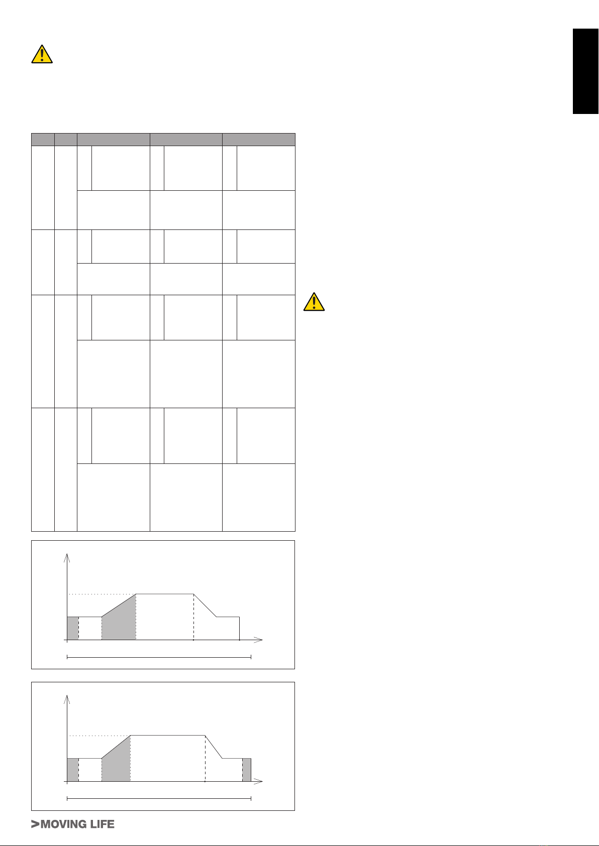
Velocità PARAMETRI IN APERTURA
0
A B
C D
Vap (4)
Corsa utile binario
Vmin (3)
Tempo
A = Tempo di oscuramento encoder (9)
B = Rampa di accelerazione in apertura (7)
C = Punto di inizio rallentamento in apertura (1)
D = Punto di arresto dal fine corsa in apertura (FCA) (10)
Velocità PARAMETRI IN CHIUSURA
0
A B
C
D
Vch (5)
Corsa utile binario
Vmin (3)
Tempo
A = Tempo di oscuramento encoder (9)
B = Rampa di accelerazione in chiusura (8)
C = Punto di inizio rallentamento in chiusura (2)
D = Posizione limite di controllo ostacoli in chiusura (11)
Note:
(1) se si varia questo parametro, cioè si sposta +/- in avanti
la zona in cui viene considerato necorsa un ev. ostacolo, è
necessario regolare ”Posizione ne corsa in apertura” (10),
in modo tale da garantire lo spazio necessario ad eseguire
una corsa completa.
Procedura consigliata per la regolazione:
1_ posizionare i dip7 e 8 sulla combinazione necessaria a
modicare il parametro voluto;
2_ regolare a metà corsa TUTTI e TRE i trimmer;
3_ premere il tasto ENTER per confermare i parametri;
4_ eseguire una manovra apre/chiude completa e verica-
re se il comportamento è soddisfacente;
5_ regolare i trimmer;
6_ premere il tasto ENTER;
7_ procedere come dal punto 4 no ad ottenere il compor-
tamento voluto;
8_ ripetere la procedura per tutte le combinazioni dei dip 7
e 8 al ne di regolare tutti i parametri;
N.B. non è possibile modicare un solo parametro.
Ogni volta si devono regolare e vericare tutti e tre i
settaggi della combinazione selezionata.
Per riportare la centrale alla congurazione standard
(impostazioni di fabbrica), è necessario premere e
mantanere premuto il tasto ENTER per almeno 5 sec.
13_ MALFUNZIONAMENTO: CAUSE E RIMEDI
L’automazione non parte
a_ Vericare con lo strumento (Multimetro) la presenza dell’ali-
mentazione 230Vac;
b_ Vericare che i contatti N.C. della scheda siano effettiva-
mente normalmente chiusi (3 led verdi accesi) e che i led
rossi dei comandi di apertura siano spenti;
c_ Impostare il dip 6 (fototest) su OFF;
d_ Aumentare il trimmer FRC e FRA al massimo;
e_ Controllare con lo strumento (Multimetro) che i fusibili siano
integri.
Il radiocomando ha poca portata
a_ Controllare che il collegamento della massa e del segnale
dell’antenna non sia invertito;
b_ Non eseguire giunzioni per allungare il cavo dell’antenna;
c_ Non installare l’antenna in posizioni basse o in posizioni
nascoste dalla muratura o dal pilastro;
d_ Controllare lo stato delle pile del radiocomando.
La porta si apre al contrario
a_ Invertire il collegamento del motore (li ROSSO e NERO
sul motore).

12
T-SKY Series
DICHIARAZIONE DI INCORPORAZIONE DEL COSTRUTTORE
(ai sensi della Direttiva Europea 2006/42/CE AlI. II.B)
Fabbricante: TAU S.r.l.
Indirizzo: Via E. Fermi, 43
36066 Sandrigo (Vi)
ITALIA
Dichiara sotto la propria responsabilità che il prodotto: Attuatore elettromeccanico
realizzato per il movimento automatico di: Porte da garage
per uso in ambiente: Residenziale
completo di: Centrale elettronica di controllo, radioricevente e radiocomando
Modello: T-SKY
Tipo: T-SKY / T-SKY1
Numero di serie: VEDI ETICHETTA ARGENTATA
Denominazione commerciale: AUTOMAZIONE PER PORTE DA GARAGE
È realizzato per essere incorporato su una chiusura (porta da garage) o per essere assemblato con altri dispositivi al ne di movimen-
tare una tale chiusura per costituire una macchine ai sensi della Direttiva Macchine 2006/42/CE.
Dichiara inoltre che questo prodotto è conforme ai requisiti essenziali di sicurezza delle seguenti ulteriori direttive CEE:
- 2006/95/CE Direttiva Bassa Tensione
- 2004/108/CE Direttiva Compatibilità Elettromagnetica
ed, ove richiesto, alla Direttiva:
- 1999/5/CE Apparecchiature Radio e apparecchiature terminali di telecomunicazione
Dichiara inoltre che non è consentito mettere in servizio il macchinario no a che la macchina in cui sarà incorporato o di cui diverrà
componente sia stata identicata e ne sia stata dichiarata la conformità alle condizioni della Direttiva 2006/42/CE.
Si impegna a trasmettere, su richiesta adeguatamente motivata delle autorità nazionali, informazioni pertinenti sulle quasi-macchine.
Sandrigo, 31/03/2010
Il Rappresentante Legale
_________________________________________
Bruno Danieli
Nome e indirizzo della persona autorizzata a costituire la documentazione tecnica pertinente:
Loris Virgilio Danieli - via E. Fermi, 43 - 3606 Sandrigo (Vi) Italia
ITALIANO
13
T-SKY Series
1_ INSTALLATION WARNINGS
GENERAL SAFETY REQUIREMENTS
1) Carefully read all instructions before installation, as they
provide important instructions regarding the safety, in-
stallation, operation and maintenance. Incorrect instal-
lation or use of the product may lead to serious physical
injury.
2) Never leave packaging materials (plastic, polystyrene etc.)
within the reach of children as they constitute a potential haz-
ard.
3) Keep the instructions in a safe place for future consultation.
4) This product has been designed and constructed exclusively
for the use specied in this documentation. Any other use not
specied herein may impair product integrity and/or consti-
tute a hazard.
5) TAU declines all liability for improper use or use other than as
specied for this automation.
6) Never install the product in explosive atmospheres.
7) The mechanical elements must comply with the requirements
as stated in the standards EN 12604 and EN 12605. For non
European member states, in addition to the national refer-
ence standards, the above-mentioned standards must be ob-
served to ensure an adequate level of safety.
8) TAU is not responsible for failure to observe Good Practice
in construction of the doors to be power-operated, nor any
deformations occurring during use.
9) To ensure the maximum safety, in consideration of the haz-
ards that may arise during installation and use of T-SKY, the
installation procedures must be performed in full compliance
with the law, current standards and regulations. This chapter
contains general warnings, while other important warnings
are provided in chapters “Preliminary Checks” and “Commis-
sioning”.
According to the most recent legislation, the installa-
tion of a power-operated door or gate must be in full
observance of the standards envisaged by European
Directive 98/37/EC (Machinery Directive) and in particu-
lar the standards: EN 12445; EN 12453 and EN 12635,
which enable the declaration of presumed conformity.
10) Before installation, an assessment of the associated risks
must be made, including a list of the essential safety require-
ments as envisaged in Appendix I of the Machinery Directive,
specifying the relative solutions adopted. Note that the risk
assessment is one of the documents included in the automa-
tion Technical documentation.
11) Check whether other devices are needed to complete the au-
tomation with T-SKY on the basis of the specic conditions
of use and dangers present; take into account all risks of im-
pact, crushing, shearing, dragging etc. and other hazards in
general.
12) Installation must comply with all provisions of Standards EN
12453 and EN 12445. In non-EU member states, as well as
national reference standards, the afore-mentioned standards
should also be observed to guarantee an adequate level of
safety.
13) Before performing any operations on the system, disconnect
from the mains and detach the batteries.
14) On the automation power line, install a device for disconnec-
tion from the power mains with a gap between contacts equal
to or greater than 3 mm. Use of a 6A thermal magnetic circuit
breaker with multi-pole switch is recommended.
15) Check upline of the system that there is a residual current
circuit breaker with a threshold of 0.03 A.
16) Ensure that the earthing system is to professional standards
and connected to the metal section of the door.
17) The safety devices (standard EN 12978) enable the protec-
tion of danger areas from risks associated with mechani-
cal movements such as crushing, dragging and shearing.
18) The use of at least one luminous indicator is recommended
for each system, as well as a warning notice xed suitably
to the frame structure, in addition to the devices specied in
point 18.
19) TAU declines all liability for the safety and efcient operation
of the automation in the event of using system components
not produced by TAU.
20) For maintenance, use exclusively original TAU parts.
21) Never modify components that are part of the automation
system.
22) The automation may only be used after completing the com-
missioning procedure as specied in chapter 5 “Testing and
commissioning”.
23) The installer must provide all information regarding manual
operation of the system in the event of an emergency and
supply the system User with the “User Guide” enclosed with
the product.
24) Never allow children or other persons to stay in the vicinity of
the product during operation.
25) Keep all radio controls or other pulse supplier device out of
the reach of children to prevent inadvertent activation of the
automation.
26) Transit below the door must occur exclusively when the auto-
mation is stationary.
27) The user must never attempt to repair or intervene directly
on the product; always contact qualied personnel for assist-
ance.
28) Before accessing internal terminals under the T-SKY cover,
disconnect all power circuits. If the disconnect device is not in
a visible location, afx a notice stating: “CAUTION: MAINTE-
NANCE IN PROGRESS”.
29) Maintenance: at least every six months, make a general
check of the system, with special reference to the efciency
of the safety devices (including, when envisaged, the opera-
tor thrust force) and release mechanisms.
30) All actions not expressly envisaged in these instructions
are strictly prohibited.
All documentation related to the system should be kept inside
or in the immediate vicinity of the control unit.
2_ PRODUCT DESCRIPTION AND INTENDED USE
(g. 1)
T-SKY is a range of gearmotors destined for the automation of sec-
tional doors and, by means of the special accessory P-100BANT
not supplied, spring or counterweight up-and-over doors, project-
ing and non-projecting.
2 solutions of T-SKY are available: one with a single track sliding
guide (L= 3m – moving parts are already assembled at the factory)
or in the 3-section version for assembly (moving parts need to be
assembled by the installer).
The irreversible system guarantees mechanical blocking of the
door when the motor is not operating, and therefore no lock is nec-
essary; an internal and external manual release (optional) enable
door manoeuvres in the event of a power failure or when out of
service.
The buffer battery accessory P-200BATTSKY (optional) is also
available, which enables certain manoeuvres in the event of a
mains power failure.
The T-SKY automation has been designed and con-
structed for indoor use and to control vehicle access.
Any other use is strictly prohibited.
1_ Base
2_ Cover
3_ Door
4_ Control unit
5_ Courtesy light
6_ Gear unit
7_ Sliding guide
8_ Drive carriage
9_ Door attachment bracket
10_ Front attachment
11_ Chain tensioner
12_ Rear attachment
13_ Release knob
ENGLISH
14
T-SKY Series
2.1_ Application limits and dimensions (g. 2)
All performance data of the products in the T-SKY range are pro-
vided in the table “Technical Data” are the only values that enable
and ensure correct evaluation for use.
The structural features of T-SKY products make them suitable for
use on sectional or up-and-over doors, within the limits as speci-
ed in the table.
Model SECTIONAL door
Height Width
T-SKY (guide P-100BINBELT/CHAIN) 2,5m 3,5m
T-SKY (guide
P-100BINBELT3/CHAIN3
) 2,5m 3,5m
T-SKY1 (guide P-100BINBELT/CHAIN) 2,5m 5m
T-SKY1 (guide
P-100BINBELT3/CHAIN3
) 2,5m 5m
Model UP-AND-OVER
door non projecting
(with accessory
P-100BANT)
Height Width
T-SKY (guide P-100BINBELT/CHAIN) 2,2m 3m
T-SKY (guide
P-100BINBELT3/CHAIN3
)2,2m 3m
T-SKY1 (guide P-100BINBELT/CHAIN) 2,2m 4m
T-SKY1 (guide
P-100BINBELT3/CHAIN3
)2,2m 4m
Model UP-AND-OVER
door projecting
(with accessory
P-100BANT)
Height Width
T-SKY (guide P-100BINBELT/CHAIN) 2,8m 3m
T-SKY (guide
P-100BINBELT3/CHAIN3
)2,8m 3m
T-SKY1 (guide P-100BINBELT/CHAIN) 2,8m 4m
T-SKY1 (guide
P-100BINBELT3/CHAIN3
)2,8m 4m
Note: if art. P-100PROC (or P-100PROB) is used, the heights stat-
ed in the tables may be increased by 1m.
The measurements stated in the tables are guideline only and
serve as a general estimate. The effective suitability of T-SKY for
the automation of a specic door depends on the degree of leaf
balance, friction on the guides and other factors, including occa-
sional events, such as wind pressure or the presence of ice, which
may obstruct leaf movement.
2.2_ Type of system and cable sections (gs. 3-4-5)
1_ Gearmotor with built-in control
2_ Photocells
3_ Photocells on post
4_ Sensitive edge
5_ Flashing light and aerial
6_ Key-operated selector switch
7_ Pushbutton panel
8_ External release (optional)
a_ 4x0,5 mm²
b_ 2x0,5 mm² + RG58
c_ 2x0,5 mm²
d_ 3x0,5 mm²
e_ 3x0,5 mm²
f_ 4x0,5 mm²
3_ INSTALLATION
T-SKY must be installed by qualied personnel in com-
pliance with current legislation, standards and regu-
lations as well as the specications in these instruc-
tions.
3.1_ Preliminary checks
Before installing T-SKY the following checks are required:
• Ensure that all material used is in perfect condition, suitable for
use and compliant with standards.
• Ensure that the door structure is suitable for power-operation.
• Ensure that the door has the force and dimensions within the
application limits as specied in paragraph 2.1.
• Ensure that the door complies with standards EN12604 and
EN12605.
• During movement, the door must never invade public areas
allocated for the transit of pedestrians or vehicles.
• During door travel, ensure that there are no points of marked
friction, both during opening and closing.
• Ensure sufcient strength of the mechanical stops and check
that there is no risk of the door derailing.
• Ensure that the door is adequately balanced, i.e. it should not
move if left stationary in any position.
• Ensure that the xing points of the various devices (photocells,
pushbuttons etc.) are located in areas protected against the
risk of impact, and that the xing surfaces are sufciently solid.
• Ensure that the minimum and maximum clearances are as
specied in gures 6 and 7.
• Ensure that parts of the operator cannot come into contact with
water or other liquids.
• Do not keep T-SKY components near sources of heat or ex-
pose to ames; these actions may damage or cause malfunc-
tions, re or hazardous situations.
• If the door is equipped with a pedestrian pass door, ensure that
this does not obstruct normal door travel; if necessary t a suit-
able interlock system.
• If the door to be automated is up-and-over, check value A of
gure 8, i.e. the minimum distance between the upper edge of
the guide and the maximum point reached by the upper edge
of the door. Otherwise T-SKY cannot be tted.
• Connect the T-SKY power plug to an electrical socket equipped
with safety earthing.
• The electrical socket must be protected by an adequate ther-
mal magnetic cut-out and residual current circuit breaker.
3.2_ Sliding guide assembly
If supplied with the sliding guide in 3 sections, these must be as-
sembled as described below:
1_ Straighten the three tracks after inserting the buttery bracket
on the section (for ceiling mounting), as shown in g. 9.
2_ Slide the joint to join the tracks (g. 10) and secure using the
screw (B g. 10) suppied.
3_ Adjust the tension of the chain/belt by means of the chain ten-
sioner nut (A g. 10) until it is sufciently taut.
Otherwise, if supplied with the pre-assembled guide, tension the
chain/belt until it is sufciently taut.
If the chain/belt is tensioned excessively, the motor will
undergo excessive stress with a consequent increase
in current absorption.
If the height of the door to be power-operated is greater than 2,5
m, the optional accessory 100PROC (for chain drive) or 100PROB
(for belt drive) is required to extend the sliding guide by 1 m. To
assemble, proceed as follows:
• guide 100BINCHAIN3 – chain drive (100PROC)
1_ Insert the additional 1-metre section inside its joint of 700 mm
(g. 11).
2_ Keep the drive carriage locked in place (A g. 12) and slide
the chain until the joint protrudes (B g. 12).
3_ Add the additional section on the chain (g. 13).
4_ Slide the chain until it is locked on the drive carriage (g. 14).
5_ Insert the additional section in the casing (with joint) and join
the four tracks as described above (gs. 9-10).
6_ Tension the chain by means of the nut (A g. 15) until it is suf-
ciently taut.
If the chain/belt is tensioned excessively, the motor will
undergo excessive stress with a consequent increase
in current absorption.
ENGLISH

15
T-SKY Series
ENGLISH
• guide 100BINCHAIN – chain drive (100PROC)
1_ Insert the additional 1-metre section inside its joint of 700 mm
(g. 11).
2_ Loosen the chain tension by means of the nut (A g. 15) and
remove the chain tensioner.
3_ Keep the drive carriage locked in place (A g. 12) and slide
the chain until the joint protrudes (B g. 12).
4_ Add the additional section on the chain (g. 13).
5_ Slide the chain until it is locked on the drive carriage (g. 14).
6_ Insert the additional section of the casing (with joint) and join
to the long track (g. 16).
7_ Fit the chain tensioner and adjust tension until the chain is
sufciently taut.
If the chain/belt is tensioned excessively, the motor will
undergo excessive stress with a consequent increase
in current absorption.
• guide 100BINBELT3 and 100BINBELT – belt drive (100PROB)
If supplied with the track in three sections, these must be assem-
bled as described at the start of this paragraph, after which the
following operations are the same for both versions:
1_ Insert the additional 1-metre section inside its joint of 700 mm
(g. 11).
2_ Loosen the belt tension by means of the nut (A g. 17).
3_ Keep the drive carriage locked in place (A g. 18) and slide
the belt until the joint protrudes (B g. 18).
4_ After removing the xing screws, extract the belt and remove
from the sliding guide (g. 19).
5_ Remove the rear attachment as shown in gure 20. This
operation requires some strength; use a rubber mallet if re-
quired.
6_ Join the 1-metre extension to the track with its joint (g. 21).
7_ Pass one end of the belt through the head section, as shown
in g. 22, and x it to the joint with the screws and wash-
ers already present (g. 23). Take care to ensure the correct
position of the belt: it must be with the teeth facing inwards,
straight without any twists.
8_ Assemble the gear unit as shown in gure 24. This operation
requires some strength; use a rubber mallet if required.
9_ Pass the free end of the belt through the carriage, to the gear
of the chain tensioner and then again through the carriage to
the joint to establish the correct length. Take care to ensure
the correct position of the belt: it must be with the teeth facing
inwards, straight without any twists.
10_ Cut the belt to the set length and x to the joint by means of
the screws and washers already present (A g. 25).
11_ Slide the belt until it is locked on the drive carriage (B g. 25).
12_ Tension the belt by means of the nut (A g. 26) until it is suf-
ciently taut.
If the chain/belt is tensioned excessively, the motor will
undergo excessive stress with a consequent increase
in current absorption.
3.3_ Fixing the gearmotor to the guide
1_ Join the gearmotor with the head of the guide, then secure by
means of the 4 screws supplied as shown in gure 27.
2_ The motor can be rotated to three different positions, as
shown in gure 6.
3.4_ Fixing the gearmotor to the ceiling
1_ In observance of positions A and B in gure 6, trace the two
xing points of the rear guide bracket at the centre of the
door. Depending on the type of material, the front bracket can
be secure by means of stud bolts, plugs or screws.
2_ After drilling holes at the envisaged points, leaving the gear-
motor on the ground, lift the guide from the front section and
secure it with two screws, plugs or stud bolts depending on
the mounting surface.
3_ Lift the sliding guide so that the rear attachment reaches the
same level as the front attachment, or to the same angle as
the horizontal track of the door (A g. 28).
4_ Measure the distance between the ceiling and interaxis of the
gear unit xing holes (B g. 28).
5_ Bend the brackets supplied to the set measurement (meas-
ure from the centre of the rst slot on the bracket).
6_ Fit the brackets on the gear unit and reposition the sliding
guide (g. 29).
7_ Mark the rear attachment xing points on the ceiling (taking
care to protect the sliding guide).
Complete guide installation.
8_ Three-sections track: repeat points 3_ to 7_ for the xing at
guide center
9_ For heavy doors or doors not running smoothly, the optional
P-100BINSUPP accessory allows a second ceiling xing
point (g. 3).
10_ Assemble the door xing bracket as shown in g. 30.
11_ With the door closed, pull the cord to release the carriage as
shown in gure 31.
12_ Slide the carriage until the leaf attachment bracket is on the
upper edge of the door, exactly perpendicular to the guide.
Then x the leaf attachment bracket with stud bolts or screws
as shown in gure 32. Use stud bolts or screws suited to the
material of the leaf, checking that it is suitable to withstand all
the force required to open and close the door.
13_ Loosen the screws of the mechanical stops, then move it in
front of the carriage, as shown on gure 33. Firmly push the
carriage in the closing direction and, once reached the posi-
tion, tighten the screws (A) fully down.
14_ For opening phase, use any available mechanical stop, both
the door one and the complete automation track are equally
ne.
15_ Attempt to move the door manually. Ensure that the carriage
slides freely, without friction on the guide, and that manual
manoeuvres are smooth without requiring particular effort.
3.5_ Installation of various devices
To install the other devices envisaged, refer to the
relevant instructions. Check in gure 2 the devices that can be
connected to T-SKY.
3.6_ Optional accessories
The range of T-SKY motors can be completed with the following
optional accessories:
• P-100BANT adaptor for up-and-over doors;
• P-150SETSKY external manual release for application on han-
dle;
• P-750BATTSKY Battery Pack;
• P-100BINSUPP Additional Ceiling Fixing Kit;
• P-100PROC Extension for T-SKY;
• P-100PROB Extension for T-SKY;
• 100BANT (g. 34)
Adaptor for up-and-over doors
100BANT must be used to power operate counterweight up-and-
over doors with drive models T-SKY and T-SKY1.
• 150SETSKY
External release (see relative instructions).
• 750BATTSKY
Battery pack (see relative instructions).
• 100BINSUPP (g. 3)
Additional Ceiling Fixing Kit.
• 100PROC (g. 9 - 14)
Extension for T-SKY with chain.
• 100PROB (g. 17 - 26)
Extension for T-SKY with belt.

16
T-SKY Series
3.7_ Electrical connections
All electrical connections must be made withthe sy-
stem disconnected from the power supply.
1_ To open the protection cover and access the electronic con-
trol unit of T-SKY, press on the side of the cover and turn the
panel door as shown in g. 35.
2_ Route the connection cables to the various devices through
the cable clamps, leaving a length 20÷30cm more than nec-
essary. See para. 2.2 for the type of cables and gure 3 for
connections.
3_ Make the connections as shown in the diagram in gure 36.
Terminals are removable to facilitate connections.
3.8_ Connecting to the power supply
For electric power supply of T-SKY simply connect the 230 Vac line
to the transformer safety fuse holder (A g. 36).
T-SKY must be connected to the power mains by skil-
led and qualied personnel, in possession of all requi-
rements for full compliance with all legal provisions,
standards and regulations.
The electric power line must be protectedagainst short
circuits and dispersion to earth; a device must be tted
to enable shutoff of the power supply during installa-
tion or maintenance of T-SKY.
4_ K690M ELECTRONIC BOARD
4.1_ Technical specications
Board power supply 24 Vac - 50 Hz
Max. DC motor power 50 W - 24 Vdc
Quick-acting motor protection fuse
(F1 - 5x20) F 10 A
Quick-acting battery protection fuse
(F2 - 5x20) F 10 A
Quick-acting 24 Vdc auxiliary circuit protection
fuse (F3 - 5x20) F 2 A
Motor power circuit supply voltage 24 Vdc
Auxiliary device circuit power supply voltage 24 Vdc
Logic circuit power supply voltage 5 Vdc
Operating temperature -20 °C ÷ +70 °C
Housing protection rating IP 30
4.2_ Diagnostics leds
DL1 (OPEN/CLOSE) red led indicating use of OPEN/CLOSE
button
DL2 (STOP) green led indicating use of STOP but-
ton
DL4 (PHOTO) green led indicating PHOTOCELL
DL3 (ERR) red led indicating ERRORS
DL5 (POWER) green led indicating POWER ON (also
when battery powered)
4.3_ Terminal board connections
FS1 - FS2 24 Vac board power supply input – Powered by
transformer in relative compartment of T-SKY motor
and protected by fuse on the 230 Vac power line.
1-4 (Photocell) PHOTOCELL OR SAFETY DEVICE input ac-
tive on closure (Normally Closed contact); when activated,
during the closing phase, generates a door stop command
followed by complete door re-opening; in the opening
phase generates a temporary stop command until the de-
tected obstacle is removed (only if dip switch nr. 3 is set to
ON). In the case of multiple safety devices, connect all NC
contacts IN SERIES. 1= PHOTOCELL .
N.B. The photocell transmitter must always be powered by
terminals 5 and 6, as the safety system check is per-
formed on the latter (Fototest).
To disable the safety system test function, or when
using the photocells, set dipswitch 6 to OFF. If the fo-
totest function fails, there is a control unit fault.
2-4 (Stop) STOP button input (Normally Closed contact); stops
the door at any point of travel, temporarily inhibiting auto-
matic closure, if programmed. It resumes operation when
the OPEN/CLOSE button is pressed or radio control is
used. 2= STOP, 4= COMMON
3-4 (Open/Close) OPEN/CLOSE button input (Normally Open
contact); activates door opening and closing and is control-
led by operation of dipswitches 2 and 4. 3= OPEN/CLOSE.
5-6 (Photocell TX) 24 Vdc output, for PHOTOCELL TX POW-
ER SUPPLY (only those that perform the Fototest function)
max. nr. 1 photocell transmitter.
5= NEGATIVE, 6= POSITIVE.
6-7 (Photocell RX) 24 Vdc output, max. 15 W, for POWER
SUPPLY OF RX AND POSSIBLE OTHER TX ELEMENTS
OF PHOTOCELLS, EXTERNAL RECEIVERS etc; connect
max. 3 pairs of photocells. 6= POSITIVE, 7= NEGATIVE.
8-9 (Flashing light) 24 Vdc FLASHING LIGHT output (max. 15
W). The signal supplied is already specially modulated for
direct use. The ashing frequency doubles during the clos-
ing phase. 8= POSITIVE, 9= NEGATIVE.
10-11 (Antenna) AERIAL input for built-in RX 433,92 MHz. 10=
EARTH, 11= SIGNAL.
M4 quick connector for ENCODER and MOTOR connec-
tion. Brown = 5 Vdc (+5V), green = ENCODER SIGNAL
(ENC), White = 0 Vdc (GND), black = MOTOR NEGA-
TIVE, red = MOTOR POSITIVE.
17 - 18 24V – 1.2Ah BATTERY input.
4.4_ Memorisation procedure
IMPORTANT: After powering up the control panel, wait for 2
seconds before starting the adjustment procedures.
On completion of automation installation:
1_ bring the door to approx. 1 m from the closing stop;
2_ position dipswitch no. 10 to ON;
3_ activate the automation via one of the following inputs: O/C,
radio control or board button (O/C).
4_ the door should start to close.
N.B.: if the door opens, suspend programming and reset the
electrical panel (disconnect the panel from the power
supply for at least 5 sec. and return dipswitch no. 10 to
OFF), and while disconnected, invert the motor supply
wires. Then resume the procedure from point 1.
5_ at the end of closure, after an interval of approx. 2 seconds, a
total opening and new closing cycle is performed automatically;
6_ at the end of closing, wait for led DL3 to light up permanently,
then position dipswitch no. 10 to OFF;
7_ the automation is now ready for operation.
Make the logic settings.
N.B.: by means of any adjustment device on the control
panel (trimmers or dipswitches) perform a complete
manoeuvre (opening and closing) of the automation to
apply the new settings.
4.5_ Logic settings
TRIMMER
T.C.A. Automatic closing time setting trimmer. From 0 to 120
sec.
Turn clockwise to increase the time interval.
FRA Trimmer for adjustment of force during the opening
phase.
Turn clockwise to increase force.
ENGLISH

17
T-SKY Series
ENGLISH
FRC Trimmer for adjustment of force during the closing
phase.
Turn clockwise to increase force.
TRM4 }see technical menu for dipswitches 7-8.TRM5
TRM6
4.6_ Dip-switches
1 on: at the end of opening, the door closes automatically after a
time interval set on the trimmer A.C.T.;
off: closure requires a manual command;
2 on: with the automation running, a sequence of open/close
commands activates a door sequence OPEN-CLOSE-OPEN-
CLOSE, etc. (see also dip switch 4);
off: in the same conditions, a sequence of open/close com-
mands activates a door sequence OPEN-STOP-CLOSE-
STOP-OPEN-STOP, etc. (step-step function);
3 on: during the opening phase, the photocell intervenes, stop-
ping the door until the detected obstacle is removed. The door
resumes opening when the obstacle is removed;
off: the photocell does not intervene during opening;
4 on: NO-REVERSE function active; the door ignores the clos-
ing commands during opening and inverts the direction of door
travel only in the closing phase;
off: on activation of the open-close button, the direction of trav-
el is inverted also in the opening phase;
5 on: the pre-ashing function is enabled;
off: the pre-ashing function is disabled;
6 on: the “photocell check” function is enabled;
off: the “photocell check” function is disabled. N.B. to be used
when photocells are not used;
7 - 8 ADVANCED PARAMETER SETTINGS: see TECHNI-
CAL MENU
9 on: to select if using mod. T-SKY1;
off: to select if using mod. T-SKY;
10 on: this enables the function for memorising travel in self-learn-
ing mode;
off: position to leave the dipswitch in at the end of the memori-
sation procedure.
4.7_ Features of K690M
LED - DL3
As well as indicating the presence of power, this led indicates any
errors by means of a set series of ashing signals:
• always lit: normal operation;
• 1 ash: backup battery voltage less than 11.3 Vdc;
Check the mains voltage, charge the battery, replace the bat-
tery;
• 2 ashes: fototest error;
Disable fototest (dipswitch 6 set to OFF), check photocell op-
eration and relative connection;
• 3 ashes: mains power failure;
check thermal magnetic cut-out (upline of system), check fus-
es;
• 4 ashes: max. current limit exceeded;
Peak of excessive motor absorption, ensure absence of obsta-
cles along door travel, check motor absorption under no load
and applied on the door;
• 5 ashes: no encoder signal;
check wiring, check encoder, check that the motor rotates free-
ly when powered directly by battery, check fuse F1;
• 6 ashes: presence of obstacle after 5 failed closing at-
tempts;
Ensure absence of obstacles along door travel and smooth
movement of the door;
• 7 ashes: no memorisation procedure performed;
Perform memorisation procedure.
• 8 ashes: no motor signal;
check wiring, check that the motor rotates freely when powered
directly by battery, check fuse F1;
Multiple error signals are indicated with a pause of 2 seconds be-
tween one signal and the next. The error signals persist until a
complete automation manoeuvre is performed (opening and clos-
ing).
If the encoder is activated 5 times consecutively (during the same
opening or closing manoeuvre), the control unit sets to the decel-
eration phase to locate the closing stop position. The automation
must complete a closing manoeuvre to be able to reset; otherwise
the closing limit position will be searched for each time one of the
safety devices is activated.
BATTERY CHARGE CARD (BUILT-IN)
If the battery is connected, the automation will be operative also
in the event of a power failure. If voltage falls below 11.3 Vdc, the
automation stops operating (the control panel remains powered); if
it falls below 10.2 Vdc, the card disconnects the battery completely
(the control panel is no longer powered).
OBSTACLE DETECTION
The obstacle detection function (settable via the trimmer FR), if
activated during the opening phase, re-closes the door by approx.
20 cm, and during closing activates a complete opening cycle.
IMPORTANT: the control panel logic may interpret mechani-
cal friction as an obstacle.
N.B. the O/C button on the card has the same function as the
OPEN/CLOSE key.
4.8_ Advanced functions
Clock function: a timer may be used (e.g. weekly), connected to
the input of the open-close button, to keep the door open in set
time intervals, to then enable automatic re-closure.
N.B. the door remains open while the Op/Cl input is engaged.
Open only” function: by setting dipswitch 1 to ON and dipswitch
4 to OFF, the Op/Cl input will only operate as an opening com-
mand, while the door will close exclusively after the set interval for
automatic closure.
4.9_ Built-in 433.92 MHz radio receiver
The radio receiver can learn up to max. 30 codes in dipswitch
mode (TXD2, TXD4, BUG2, BUG4, K-SLIM, K-SLIM-C, T-4, T-4C)
or rolling codes (BUG2R, BUG4R, K-SLIM-RP, T-4RP) set as re-
quired.
The learning mode (dipswitch or rolling code) is set by the rst ra-
dio control and remain so until all codes are deleted from the latter.
RADIO CONTROL LEARNING
1_ briey press the key RADIO to associate a radio control with
the function OPEN/CLOSE;
2_ led DL3 turns off to indicate code learning mode (if no code is
entered within 10 seconds, the card exits programming mode);
3_ press the key of the radio control to be used;
4_ led DL3 turns on again to conrm memorisation (if this does not
occur, wait 10 seconds and repeat the steps from point 1);
5_ to memorise other radio controls, repeat the procedure from
point 1, for up to a maximum of 30 transmitters.
6_ to exit learning mode without memorising a code, briey press
the key RADIO.
N.B.: if the maximum number of radio controls is reached
(30), led DL3 ashes quickly for approx. 3 seconds,
without performing memorisation.

18
T-SKY Series
REMOTE PROGRAMMING VIA T-4RP, K-SLIM-RP and BUG-R
It is also possible to learn the new versions of the radio controls T-
4RP, K-SLIM-RP and BUG-R remotely, i.e. without acting directly
on the receiver programming keys.
A radio control previously programmed on the receiver is all that is
needed to open the remote programming procedure for new radio
controls, programmed via TAUPROG.
Activation of self-learning mode of the control unit and memo-
risation of the new radio control.
This operation enables memorisation of the new radio control code
on the control unit, but an operational “RP” radio control must al-
ready be available. The subsequent operations must be performed
in the vicinity of the system control unit. Activation of self-learning
mode on the control unit and memorisation of the new radio con-
trol:
1On the operative (old) radio
control, press and hold the key
for channel 1, and press the
channel 2 key three times.
4At this point the control unit
conrms changeover to pro-
gramming mode by activat-
ing the ashing light (except
for external receivers in the
RXDC series).
2Release the keys. The radio
control led starts ashing to
indicate that the self-learning
mode is enabled.
5 Press the radio control key to
be memorised again. If pro-
gramming is successful, the
control unit ashing light turns
off.
3Still on the operative (old)
radio control, press the key
currently used to activate the
automation for at least 3 sec-
onds.
DELETING RADIO CONTROLS
1_ press and hold the RADIO key for approx. 3 seconds to delete
all associated radio controls;
2_ led DL3 starts ashing slowly to indicate that deletion mode is
enabled;
3_ release the RADIO key and press again for 3 seconds;
4_ led DL3 turns off for approx. 3 seconds, and then remains lit to
conrm deletion;
6_ to exit deletion mode, briey press the RADIO key.
IMPORTANT: To memorise a new type of remote control (e.g.
from dipswitch to rolling code mode or vice versa) all codes
present must rst be deleted.
5_ MANUAL RELEASE
If manual movement of the door is necessary, due to a power fail-
ure or problem with the automation, the release device is used as
follows:
1_ In the case of the traditional release system, pull the knob
downwards as shown in g. 31.
2_ In the case of external release (8 g. 3), turn the handle.
3_ Manually open or close the door.
6_ RESTORING NORMAL OPERATION
To restore normal automation operation, return the door to the ini-
tial position when you hear the carriage re-engage.
Caution: if you do not hear the carriage re-engage (when
the initial position is with the door closed), activate the op-
erator (via radio control, key-operated selector switch etc.); a
number of complete manoeuvres are required to repeat auto-
matic self-learning of the travel limits.
7_ FINAL CHECKS AND START-UP
Immediately after powering up T-SKY, perform a number of simple
checks:
- Ensure that the motor does not activate any door movement
and that the courtesy light is off.
If this is not so, disconnect the control unit from the power supply
immediately and check the electrical connections carefully.
Other useful information for troubleshooting can be found in chap-
ter 11 “Troubleshooting”.
8_ TESTING AND COMMISSIONING
This is the most important phase of automation set-up to ensure
maximum system safety.
The test can also be performed as a periodic check of automation
devices.
Testing of the entire system must be performed by
skilled and qualied personnel, who are responsible
for the tests required to verify the solutions adopted
according to the risks present, and for ensuring ob-
servance of all legal provisions, standards and regula-
tions, with particular reference to all requirements of
the standard EN12445 which establishes the test meth-
ods for testing automations for power-operated gates
and doors.
8.1_ Testing
Each automation component, such as sensitive edges, photocells,
emergency stop, etc., requires a specic testing phase; for these
devices take care to follow the procedures specied in the respec-
tive instruction manual.
To test T-SKY, perform the following sequence of operations:
1_ Ensure that all contents of chapter 1 “WARNINGS” are strictly
observed.
2_ Release the door by pulling the release cord downwards.
Check that it is possible to move the door in the opening and
closing directions with a maximum force of 225N.
3_ Re-engage the carriage.
4_ Using the selector or radio transmitter, test door closing and
opening and ensure that movement is as envisaged.
5_ A number of tests are recommended to assess smoothness
of door movement and check for any assembly or adjustment
defects, as well as for any points of friction.
6_ Check operation of all system safety devices one at a time
(photocells, sensitive edges etc.);
7_ To test photocells and in particular that there is no interfer-
ence with other devices, pass a cylinder (diameter 5cm,
length 30cm) through the optic axis joining the pair of pho-
tocells, rst close to the TX and then the RX and then mid-
way between the two. Ensure that in all cases the device
engages, changing from the active status to alarm status and
vice versa, and nally that the action envisaged occurs on the
control unit, for example that during the Closing manoeuvre,
the door inverts the current movement.
8_ If hazardous situations generated by the moving door are
protected by means of impact force limitation, measure the
force as specied in the standard EN 12445. If the settings
“speed” and “gearmotor force” control are used as an aux-
iliary function with the system for reduction of impact force,
test and identify the setting that obtains the best results.
ENGLISH

19
T-SKY Series
ENGLISH
8.2_ Commissioning
Commissioning can only be performed after positive results of all
testing phases. Partial or “makeshift” commissioning is strictly pro-
hibited.
1_ Prepare the automation technical documentation (to be con-
served for at least 10 years), which must contain the follow-
ing documents: an overall layout diagram of the automation,
electrical wiring diagram, risk assessment and relative solu-
tions adopted, manufacturer’s declaration of conformity for all
devices used (for T-SKY use the EC declaration of conformity
enclosed) copy of instruction manual for operation and the
automation maintenance schedule.
2_ Permanently afx a label or plate on the door, indicating the
operations for manual release and manoeuvres (use the g-
ures in the “User Guide”).
3_ Permanently afx a label or plate on the door with this image
(min. height 60mm).
4_ Afx a dataplate on the door, specifying at least the following
data: type of automation, name and address of manufacturer
(responsible for commissioning), serial number, year of con-
struction and CE mark.
5_ Compile the automation declaration of conformity and deliver
to the owner.
6_ Compile the manual “Instructions and warnings for automa-
tion operation” and deliver to the owner.
7_ Produce and supply the owner with the automation mainte-
nance schedule (containing all maintenance instructions for
all automation devices).
8_ Before commissioning the automation, ensure that the owner
is adequately informed in writing of all associated risks and
hazards (for example of the manual of instructions and warn-
ings for automation operation).
9_ OPERATION
Use of the device for purposes or in circumstances other than as
specied in this document is strictly prohibited. Note that this is a
mains-powered automatic device and must therefore be used with
caution. The following in particular is recommended:
1_ never touch the device with wet hands;
2_ disconnect the power supply before opening the controls box
and/or gearmotor;
3_ never pull the power cable to remove it from the socket;
4_ never touch the motor before ensuring it is completely cool;
5_ only move the door when it is completely visible;
6_ keep away from the operating range of the door when in
movement: wait until it is stationary;
7_ never allow children or animals to play in the vicinity of the
door;
8_ never allow children or unskilled persons to use the remote
control or other activation devices;
9_ perform periodic maintenance;
10_ in the event of a fault, disconnect the power supply and only
move the door manually when possible and in safety. Do not
intervene on the door; call an authorised technician for as-
sistance.
11_ never touch any mechanical part during operation;
12_ all actions not expressly envisaged in these instructions are
strictly prohibited.
10_ MAINTENANCE AND DISPOSAL
This chapter describes the procedures for drawing up a mainte-
nance schedule and disposal of T-SKY.
10.1_ Maintenance
To maintain a constant level of safety and guarantee maximum
lifetime of the entire automation, regular maintenance is required.
Maintenance must be performed in strict observance of
all safety instructions in this manual and in compliance
with current legislation and standards.
For devices other than T-SKY follow the respective maintenance
schedules.
1_ For T-SKY route maintenance is required within maximum six
months or 3000 duty cycles from the previous maintenance.
2_ Disconnect all electric power supply sources, including any
backup batteries.
3_ Check the condition of all automation materials, with special
attention to possible erosion or oxidation of structural parts;
replace any parts that do not guarantee total reliability.
4_ Check the state or wear of all moving parts: belt, carriage,
pinions and all door parts; replace any parts if worn.
5_ Reconnect the power supply sources and perform all checks
and tests as envisaged in paragraph “6.1 Testing”.
10.2_ Special maintenance
If more complex operations are required on electro-mechanical
parts, the faulty part should be removed to enable repairs in the
manufacturer’s workshop by technicians or other authorised cen-
tre.
10.3_ Disposal
T-SKY is made up of different types of material; some may be re-
cycled, such as steel, aluminium, plastic, or electric cables, while
others must be disposed of: batteries and electronic boards.
Some components may contain pollutant substances;
do not dispose of into the environment.Seek informa-
tion on recycling or disposal systems in observance of
current and local standards.
1_ Disconnect the automation and any backup battery from the
electrical mains.
2_ Disassemble all devices and accessories, in reverse order of
the procedures described in chapter “3 Installation”.
3_ Separate where possible all parts which may or must be re-
cycled or disposed of differently, for example metal parts from
plastic parts, electronic boards etc.
4_ Sort and assign the separated materials to specialist waster
recovery and disposal centres in your local area.
11_ NOISE LEVELS
The noise emission level of the T-SKY operator, from the work po-
sition, is 52 dB(A).
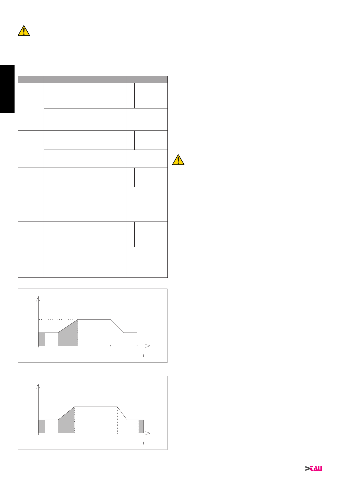
20
T-SKY Series
12_ TECHNICAL MENU
The control unit is supplied with standard factory set-
tings, suitable to move most doors commercially avail-
able, in compliance with European standards.
However a series of parameters may be modied, by means of
dipswitches 7-8 and trimmers TRM4, TRM5 and TRM6.
The function of these trimmers varies according to the position of
dipswitches 7-8, as specied in the table below.
Dip7 Dip8 TRM4 TRM5 TRM6
OFF OFF
1
Deceleration
start point
during
opening
2
Deceleration
start point
during closing
3Minimum
speed(Vmin)
Turning the trimmer clock-
wise, the door forestalls
the deceleration phase.
Turning the trimmer clock-
wise, the door forestalls
the deceleration phase.
Turning the trimmer
clockwise, the minimum
speed increases once
the deceleration phase is
complete.
OFF ON
4Opening
speed (Vap) 5Closing
speed (Vch) 6
Thrust on
closing end-
stop
Turning the trimmer
clockwise, the speed
increases.
Turning the trimmer
clockwise, the speed
increases.
Turning the trimmer
clockwise, the thrust
time against the endstop
increases.
ON OFF
7
Accelera-
tion ramp on
opening
8
Acceleration
ramp on
closing
9
Encoder
blackout time
(motor start)
Turning the trimmer clock-
wise, the acceleration
ramp lasts longer.
Turning the trimmer clock-
wise, the acceleration
ramp lasts longer.
Turning the trimmer clock-
wise, the time increases
(on start-up) when the
encoder signal is ignored
(to prevent difcult starts
(e.g. sectional doors that
are not parallel to the
oor, etc.).
ON ON
10
Endstop
halt point
on opening
(FCA)
11
Max. obsta-
cle control
position on
closing1
12
Reduction of
loose chain/
belt
Turning the trimmer clock-
wise, the halt distance
from the opening endstop
increases (to protect the
mechanical efciency of
the product).
Turning the trimmer clock-
wise, the zone considered
as closing endstop
increases (to avoid small
obstacles, like stones,
etc., causing accidental or
repeated re-openings).
Turning the trimmer clock-
wise, the irritating loosen-
ing of the chain/belt at the
bottom is avoided, which
occurs when the closing
phase is complete.
Speed OPENING PARAMETERS
0
A B
C D
Vap (4)
Guide useful trave
Vmin (3)
Time
A = Encoder blackout time (9)
B = Acceleration ramp on opening (7)
C = Deceleration start point during opening (1)
D = Endstop halt point on opening (FCA) (10)
Speed CLOSING PARAMETERS
0
A B
C
D
Vch (5)
Guide useful travel
Vmin (3)
Time
A = Encoder blackout time (9)
B = Acceleration ramp on closing (8)
C = Deceleration start point during closing (2)
D = Max. obstacle control position on closing (11)
Notes:
(1) if this parameter is modied, i.e. if the stopping distance
from the mechanical limiter is moved +/- forward, the value
”Opening limit position” (10) must be adjusted to guarantee
the space required to complete a complete manoeuvre.
Recommended procedure for adjustment:
1_ position dipswitches 7 and 8 on the combination re-
quired to modify the specic parameter;
2_ set ALL THREE trimmers to mid-way.
3_ press ENTER to conrm the parameters;
4_ perform a complete open/close manoeuvre and check
that the response is correct.
5_ adjust the trimmers;
6_ press ENTER;
7_ proceed as per point 4 to obtain the required response.
8_ repeat the procedure for all dip 7 and dip 8 combina-
tions to adjust all the parameters;
N.B. it is not possible to modify one parameter only. All
three parameters of the selected combination need to
be adjusted each time.
To restore the standard conguration to the control
unit (factory settings), press and hold ENTER for at le-
ast 5 sec.
13_ MALFUNCTIONS: TROUBLESHOOTING
The automation does not start
a_ Use a Multimeter to check presence of 230 Vac supply volt-
age.
b_ Check that the NC contacts of the card are effectively nor-
mally closed (3 green leds lit) and that the red leds for open-
ing commands are off.
c_ Set dipswitch 6 (fototest) to OFF;
d_ Set trimmers FRC and FRA to the maximum value;
e_ Use the Multimeter to check that the fuses are intact.
The radio control range is low
a_ Check that the earth connection and aerial signal have not
been inverted;
b_ Do not make joints to extend the aerial cable;
c_ Do not install the aerial at low heights or concealed by walls
or columns;
d_ Check status of the radio control batteries.
The door opens in the opposite direction
a_ Invert the motor connection (RED and BLACK wires on the
motor).
ENGLISH
Other manuals for T-SKY
3
Table of contents
Other tau Garage Door Opener manuals


Popular Garage Door Opener manuals by other brands


Chamberlain
Chamberlain MotorLift ML500 instruction manual

Chamberlain
Chamberlain Whisper Drive Security+ 459950 owner's manual

Chamberlain
Chamberlain Power Drive Security+ PD210CS owner's manual

Craftsman
Craftsman 139.53992 owner's manual

DELTA DORE
DELTA DORE TYXIA 6410 installation guide

Calimet
Calimet CM5-DCNB instruction manual

Chamberlain
Chamberlain 3265C 1/2 HP owner's manual

Abloy
Abloy DA460 Installation and commissioning manual

Automatic Technology
Automatic Technology GDO-11 Ero instruction manual

Chamberlain
Chamberlain ELITE Series user guide

Chamberlain
Chamberlain M150 1/2 HP owner's manual

King gates
King gates INTRO Installation and use instructions and warnings