tau SKYBOX Series User manual

1
SKYBOX Series
Edizione 03 - anno 2007 rev. 17 - del 09/06/2009http://www.tauitalia.com
SKYBOX Series
AUTOMAZIONI PER PORTE BASCULANTI
AUTOMATIONS FOR OVERHEAD DOORS
AUTOMATISIERUNGEN FÜR SCHWINGTORE
AUTOMATISATIONS POUR PORTES BASCULANTES
AUTOMATIZACIÓNES PARA PUERTAS BASCULANTES
>ITALIANO
>ENGLISH
>DEUTSCH
>FRANÇAIS
>ESPAÑOL
TAU srl via E. Fermi, 43 – 36066 Sandrigo (Vi) Italy – Tel. +390444750190 Fax. +390444750376 E-mail: [email protected]
MANUALE D’USO E MANUTENZIONE
USE AND MAINTENANCE MANUAL
BEDIENUNGS - UND WARTUNGSANLEITUNG
MANUEL D’EMPLOI ET D’ENTRETIEN
MANUAL DE USO Y MANTENIMIENTO

2
SKYBOX Series
Los datos describidos en este manual son puramente indicativos. La TAU se reserva el derecho de modicarlos en cualquier
momento.
El Fabricante se reserva el derecho de modicar o actualizar el producto sin aviso previo. Posibles imprecisiones o errores en este
manual serán corregidos en la próxima edición.
Cuando abra el embalaje, controle que el producto esté íntegro. Recicle los materiales según la normativa vigente.
Este producto ha sido diseñado y realizado para automatizar puertas que se abran manualmente y que estén bien equilibradas; por dicho
motivo, la puerta se debe poder abrir completamente con una fuerza inferior a 150 N (15 kg) y, detenida en cualquier posición, accionado el
dispositivo de desbloqueo, no debe tender a bajar.
La instalación del producto tiene que ser efectuada por personal cualicado. El Fabricante Tau no se asume ninguna
responsabilidad por lesiones a personas o averías a cosas causadas por una instalación incorrecta del equipo o la por la
inobservancia de la normativa vigente (véase Directiva de Máquinas).
Italiano
I dati riportati nel presente manuale sono puramente indicativi. La TAU si riserva il diritto di modicarli in qualsiasi momento.
La Casa costruttrice si riserva il diritto di apportare modiche o miglioramenti al prodotto senza alcun preavviso. Eventuali imprecisioni
o errori riscontrabili nel presente fascicolo, saranno corretti nella prossima edizione.
All’apertura dell’imballo vericare che il prodotto sia integro. Riciclare i materiali secondo la normativa vigente.
Questo prodotto è stato progettato e realizzato per automatizzare porte apribili manualmente e ben bilanciate, perciò, la porta deve
potersi aprire per tutta la corsa con una forza inferiore a 150N (15 kg) e fermato in qualsiasi posizione, azionato lo sblocco, non deve
accennare a scendere.
L’installazione del prodotto dovrà essere effettuata da personale qualicato. La Ditta costruttrice Tau declina ogni responsabilità
per danni derivanti a cose e/o persone dovuti ad un’eventuale errata installazione dell’impianto o la non messa a Norma dello
stesso secondo le vigenti Leggi (vedi Direttiva Macchine).
English
Deutsch
Français
Español
The data described in this handbook are purely a guide. TAU reserves the right to change them in any moment.
The manufacturer reserves the right to modify or improve products without prior notice. Any inaccuracies or errors found in this handbook
will be corrected in the next edition.
When opening the packing please check that the product is intact. Please recycle materials in compliance with current regulations.
This product has been designed and built for automating well-balanced doors that can be opened manually; it must therefore be possible
to completely open the door using a force of less than 150N (15 kg). No matter what position it is stopped at, it must not descend when
the unlock device is released.
This product may only be installed by a qualied tter. The manufacturer declines all liability for damage to property and/or
personal injury deriving from the incorrect installation of the system or its non-compliance with current law (see Machinery
Directive).
Les données décrites dans ce manual sont purement indicatives. La TAU se réserve le droit de les modier à n’importe quel moment.
Le Constructeur se réserve le droit d’apporter des modications ou des améliorations au produit sans aucun préavis. Les éventuelles
imprécisions ou erreurs présentes dans ce fascicule seront corrigées dans la prochaine édition.
À l’ouverture de l’emballage, vérier que le produit est intact. Recycler les matériaux suivant les normes en vigueur.
Ce produit a été projeté et réalisé pour automatiser des portes s’ouvrant manuellement et bien équilibrées ; par conséquent, la porte
doit pouvoir s’ouvrir sur toute la course avec une force inférieure à 150N (15 kg) et avec le motoréducteur arrêté dans une position
quelconque, après avoir actionné le déblocage, la porte ne doit amorcer aucun mouvement de descente.
L’installation du produit devra être effectuée par du personnel qualié. Tau décline toute responsabilité pour les dommages
aux choses et/ou personnes dus à une éventuelle installation erronée de l’automatisme ou à la non-mise aux normes suivant
les lois en vigueur (voir Directive Machines).
Die beschriebenen Daten in der vorliegenden Betriebsanleitung sind rein indikativ. TAU behält sich vor, diese in jedem Moment zu
modizieren.
Der Hersteller behält sich das Recht vor, ohne vorherige Benachrichtung Änderungen oder Verbesserungen am Produkt anzubringen.
Ungenauigkeiten oder Fehler, die in der vorliegenden Ausgabe festgestellt werden, werden in der nächsten Ausgabe berichtigt.
Beim Öffnen der Verpackung prüfen, dass das Produkt keine Schäden aufweist. Die Materialien nach den gültigen Vorschriften recyclen.
Dieses Produkt wurde geplant und hergestellt, um von Hand aufmachbare und gut ausgeglichene Tore zu öffnen; man muss daher
das Tor auf seinem gesamten Lauf mit einer Kraft unter 150N (15 kg) öffnen und in jeder Stellung anhalten können; nachdem die
Entriegelung betätigt ist, darf das Tor nicht nach unten gehen.
Die Installation des Produktes muss von Fachpersonal ausgeführt werden. Die Herstellerrma TAU übernimmt keinerlei
Haftung für Personen- und/oder Sachschäden aufgrund einer falschen Installation der Anlage oder der Nichtkonformität
derselben mit den gültigen Gesetzen (siehe Maschinenrichtlinie).
D-MNL0SKYBOXE

3
SKYBOX Series
AVVERTENZE E ISTRUZIONI PER L’INSTALLATORE
Tau si congratula per la scelta del prodotto e vi invita a leggere con molta attenzione queste pagine.
Al ne di renderle semplici, le istruzioni sono state impaginate seguendo l’ordine delle varie fasi d’installazione dell’impianto.
Leggere attentamente le istruzioni prima di procedere all’installazione, in quanto forniscono importanti indicazioni concernenti la
sicurezza, l’installazione, l’uso e la manutenzione.
Tutto quello che non è espressamente previsto nel presente manuale NON è permesso. Consultare la TAU srl per ogni cosa non indicata.
Usi non indicati, infatti, potrebbero essere causa di danni al prodotto stesso e mettere in pericolo persone, animali e/o cose.
L’installazione deve essere eseguita da personale qualicato, professionalmente competente.
L’installazione, i collegamenti elettrici e le regolazioni devono essere effettuati nell’osservanza della Buona Tecnica e in ottemperanza alle
norme vigenti.
Prima di iniziare l’installazione vericare l’integrità del prodotto.
Non installare il prodotto in ambiente e atmosfera esplosivi.
Prima di installare l’automazione, apportare tutte le modiche strutturali relative alla realizzazione dei franchi di sicurezza ed alla protezione
o segregazione di tutte le zone di schiacciamento, cesoiamento, convogliamento e di pericolo in genere. Vericare che la struttura esistente
abbia i necessari criteri di robustezza e stabilità. Per la messa a punto della coppia massima del motoriduttore, attenersi alle normative in
vigore (per l’Europa consultare le norme EN 12341-1 ed EN 12635).
L’installazione del motoriduttore, ad eccezione dei modelli interrati, deve essere realizzata sopra il livello del pavimento, al ne di evitare
rischi di allagamento.
I dispositivi di sicurezza (fotocellule, coste sensibili, stop di emergenza, ecc.) devono essere installati tenendo in considerazione: le normative
e le direttive in vigore, i criteri della Buona Tecnica, l’ambiente di installazione, la logica di funzionamento del sistema e le forze sviluppate
dalla porta o cancello motorizzati.
Scegliere percorsi brevi per i cavi. Tenere separati i cavi di potenza dai cavi di comando.
Quantunque il motoriduttore possa essere dotato di tutti i dispositivi di sicurezza si consiglia caldamente di tenere fuori della portata di
bambini o di persone inabili ogni dispositivo in grado di comandare l’apertura del cancello e che possa inavvertitamente essere usato senza
sorveglianza.
Applicare le segnalazioni previste dalle norme vigenti per individuare le zone pericolose. Ogni installazione deve riportare in modo visibile
l’indicazione dei dati identicativi degli organi automatizzati.
Prima di collegare l’alimentazione elettrica accertarsi che i dati di targa siano rispondenti a quelli della rete di distribuzione elettrica.
Prevedere sulla rete di alimentazione un interruttore/sezionatore onnipolare con distanza d’apertura dei contatti uguale o superiore a 3
mm.
Vericare che a monte dell’impianto elettrico vi siano un interruttore differenziale e una protezione di sovracorrente adeguati (interruttore
magnetotermico C6).
Collegare l’automazione ad un efcace impianto di messa a terra eseguito come previsto dalle vigenti norme di sicurezza.
Il costruttore dell’automazione declina ogni responsabilità qualora vengano installati elementi incompatibili ai ni della sicurezza e del buon
funzionamento. Per l’eventuale riparazione o sostituzione dei prodotti, dovranno essere utilizzati esclusivamente ricambi originali.
L’installatore deve fornire tutte le informazioni relative al funzionamento automatico, manuale e di emergenza della struttura automatizzata,
e consegnare all’utilizzatore dell’impianto le istruzioni per l’uso.
Consigliamo di riporre tutta la documentazione relativa all’impianto all’interno o nelle immediate vicinanze della centralina.
WARNINGS AND INSTRUCTIONS FOR FITTERS
Congratulations on choosing this Tau product. Please read this handbook carefully.
For the sake of simplicity, the instructions are listed in order of installation.
Please read these instructions carefully before installing the product as they contain important information concerning safety,
installation, use and maintenance.
Anything not expressly specied in this handbook is FORBIDDEN. Contact TAU srl for information regarding any points which may not
have been specied in the present manual.
Operations not indicated in these instructions may damage the product and put people, animals and/or and property at risk.
The equipment should be installed only by trained and qualied personnel.
Installation, electrical connections and adjustments must be made according to the rules of good workmanship and current standards.
Before beginning installation, make sure the product is undamaged.
Do not install the product in explosive environments.
Prior to installing the automation, make all structural modications in order to ensure safety distances and protect and segregate areas
in which people may be exposed to the risk of crushing, shearing, dragging or similar dangers. Make sure the existing structure is suf-
ciently sturdy and stable. Observe current legislation when adjusting maximum gearmotor torque (in Europe consult EN 12341-1 and
EN 12635 standards).
Apart from buried models, the gearmotor must be installed above ground level in order to prevent damage deriving from ooding.
The safety devices (photocells, sensitive edges, emergency stop devices, etc.) must be installed according to current legislation and
directives, the rules of good workmanship, the installation area, the operating logic of the system and the forces developed by the pow-
ered door or gate.
Choose short routes for the cables. Keep power cables separate from control cables.
Though the gearmotor is tted with various safety devices, we strongly recommend keeping all unattended devices capable of opening
the gate out of the reach of children or unable adults.
Fit the signs required by current regulations for identifying dangerous areas. Each installation must show the identication data of the
automated devices in a visible place.
Before connecting to the power supply, make sure the data on the rating plate correspond to the mains power supply.
Fit a multipole switch/knife switch on the power supply network with contacts opening distance of at least 3 mm.
Make sure there is a suitable circuit breaker and overcurrent protection device (thermal-magnet breaker C6) upline from the electrical
system.
Connect the automation to an efcient earth system compliant with current safety standards.
The manufacturer declines all liability if incompatible safety and components are installed. Only use original spare parts to repair or
replace the product.
The tter must provide all the information relative to the automatic, manual and emergency operation of the automated unit, and give
the user the operating instructions.
Keep all the documents concerning the system inside or near the central control unit.
Italiano
English

4
SKYBOX Series
AVERTISSEMENTS ET INSTRUCTIONS POUR L’INSTALLATEUR
Tau vous félicite de votre choix et vous invite à lire très attentivement les pages qui suivent.
An de faciliter la compréhension, l’ordre de présentation des instructions suit celui des différentes phases d’installation de l’automatisme.
Lire attentivement les instructions avant de procéder à l’installation, dans la mesure où elles fournissent des indications importantes
concernant la sécurité, l’installation, l’emploi et la maintenance.
Tout ce qui n’est pas expressément prévu dans ce manuel N’EST PAS permis. Consulter TAU srl pour tout ce qui n’est pas indiqué.
Les utilisations non indiquées, en effet, pourraient provoquer des dommages au produit et mettre en danger les personnes, les animaux et/ou
les choses.
L’installation doit être effectuée par du personnel qualié, professionnellement compétent.
L’installation, les connexions électriques et les réglages doivent être effectués dans les règles de l’art en respectant les normes en vigueur.
Avant de commencer l’installation, vérier l’intégrité du produit.
Ne pas installer le produit dans un environnement et une atmosphère explosifs.
Avant d’installer l’automatisme, apporter toutes les modications structurelles relatives à la réalisation des espaces de sécurité et à la protection
ou à l’isolement de toutes les zones d’écrasement, cisaillement et de danger en général. Vérier que la structure existante possède la robus-
tesse et la stabilité nécessaires.
Pour le réglage du couple maximum du motoréducteur, respecter les normes en vigueur (pour l’Europe
consulter les normes EN 12341-1 et EN 12635).
L’installation du motoréducteur, à l’exception des modèles enterrés, doit être réalisée au-dessus du niveau du sol an d’éviter les
risques d’inondation.
Les dispositifs de sécurité (photocellules, barres palpeuses, arrêt d’urgence, etc.) doivent être installés en tenant compte : des normes et des
directives en vigueur, des règles de l’art, du site d’installation, de la logique de fonctionnement du système et des forces générées par la porte
ou le portail motorisés.
Choisir des parcours brefs pour les câbles et maintenir les câbles de puissance séparés des câbles de commande.
Malgré tous les dispositifs de sécurité qui peuvent équiper l’automatisme, il est vivement conseillé de maintenir hors de portée des
enfants ou de personnes inaptes tout dispositif en mesure de commander l’ouverture du portail et qui, par mégarde, pourrait être
utilisé sans surveillance.
Appliquer les signalisations prévues par les normes en vigueur pour identier les zones dangereuses. Chaque installation doit reporter de
manière visible, l’indication des données d’identication des organes automatisés.
Avant de connecter l’alimentation électrique, s’assurer que les données de la plaque correspondent à celles du secteur de distribution électri-
que. Prévoir sur le secteur d’alimentation un interrupteur/sectionneur omnipolaire avec distance d’ouverture des contacts égale ou supérieure
à 3 mm.
Vérier qu’il y a en amont de l’automatisme un interrupteur différentiel et une protection contre la surcharge adéquats (interrupteur magnéto-
thermique C6).
Raccorder l’automatisme à une installation efcace de mise à la terre effectuée suivant les prescriptions des normes de sécurité en vigueur.
Le constructeur de l’automatisme décline toute responsabilité en cas d’installation de composants incompatibles en matière de sécurité et de
bon fonctionnement. Pour toute réparation ou pour tout remplacement des produits, il faudra utiliser exclusivement des pièces de rechange
originales.
L’installateur doit fournir toutes les informations relatives au fonctionnement automatique, manuel et d’urgence de la structure automatisée et
remettre à l’utilisateur de l’automatisme le mode d’emploi.
Nous conseillons de conserver toute la documentation relative à l’installation à l’intérieur de l’armoire de commande ou à proximité
immédiate.
HINWEISE UND ANWEISUNGEN FÜR DEN INSTALLATEUR
Tau gratuliert Ihnen zur Wahl dieses Produkts und bittet Sie, diese Seiten sehr aufmerksam zu lesen.
Um die Anweisungen einfach zu machen, wurden sie in der Reihenfolge der verschiedenen Installationsphasen der Anlage verfasst.
Die Anweisungen vor der Installation genau lesen, da sie wichtige Hinweise mit Bezug auf Sicherheit, Installation, Bedienung und
Wartung liefern.
Alles nicht ausdrücklich in diesen Anleitungen vorgesehene ist UNZULÄSSIG. Wenden Sie sich für alles nicht angegebene an die Firma TAU
srl.
Ein nicht angegebener Gebrauch könnte Schäden am Produkt verursachen und Personen, Tiere und/oder Gegenstände in Gefahr bringen.
Die Installation muss von beruich kompetentem Fachpersonal ausgeführt werden.
Installation, elektrische Anschlüsse und Einstellungen sind unter Beachtung der Fachtechnik und der gültigen Vorschriften auszuführen.
Das Produkt vor der Installation auf Schäden überprüfen.
Das Produkt nicht in EX-Umgebung bzw. EX-Atmosphäre installieren.
Vor der Installation der Automatisierung alle strukturellen Änderungen für das Vorhandensein der Sicherheitsabstände und den Schutz aller
Bereiche ausführen, in denen Quetsch-, Schnitt- und Mitnehmgefahr und Gefahren allgemein bestehen. Prüfen, ob die vorhandene Struktur
die erforderliche Robustheit und Stabilität besitzt.
Für die Einstellung des maximalen Drehmoments des Getriebemotors sind die gültigen
Vorschriften zu beachten (für Europa siehe die Normen EN 12341-1 und EN 12635).
Die Installation des Getriebemotors muss, Unterurmodelle ausgenommen, über der Bodenhöhe erfolgen, um Überschwemmungsgefahr
zu vermeiden.
Sicherheitsvorrichtungen (Fotozellen, Sicherheitsleisten, Notstop usw.) müssen unter Berücksichtigung des folgenden installiert werden: gültige
Vorschriften und Verordnungen, korrekte Fachtechnik, Installationsumgebung, Betriebslogik des Systems und Kräfte, die vom motorbetriebenen
Tor entwickelt werden.
Kurze Strecken beim Verlegen der Kabel wählen. Leistungskabel von Steuerkabeln getrennt halten.
Auch wenn der Getriebemotor mit allen Sicherheitsvorrichtungen ausgestattet werden kann, empfehlen wir, Vorrichtungen zur Betätigung
eines Tors, die ohne Überwachung zufällig benutzt werden könnten, außer der Reichweite von Kindern oder Personen mit Handicaps
zu halten.
Zur Kennzeichnung von Gefahrenbereichen die laut gültigen Vorschriften vorgesehenen Beschilderungen anbringen. An jeder Installation
müssen die Kenndaten der automatisierten Elemente sichtbar angegeben sein.
Vor dem Anschluss der Stromversorgung ist sicher zu stellen, dass die Kenndaten mit jenen des Stromnetzes übereinstimmen.
Am Versorgungsnetz einen allpoligen Schalter/Trennschalter mit Öffnungsabstand der Kontakte von oder über 3 mm vorsehen.
Prüfen, dass vor der elektrischen Anlage ein Differentialschalter und ein geeigneter Überstromschutz (magnetothermischer Schalter C6) vor-
handen sind.
Die Automatisierung an eine wirksame Erdungsanlage anschließen, die nach den gültigen Sicherheitsvorschriften ausgeführt ist.
Der Hersteller der Automatisierung übernimmt keinerlei Haftung, falls Bestandteile installiert werden, die – was Sicherheit und korrekten Betrieb
betrifft – nicht kompatibel sind. Zur Reparatur oder zum Ersatz der Produkte dürfen ausschließlich Originalersatzteile verwendet werden.
Der Installateur hat alle Auskünfte über den automatischen und manuellen Betrieb und den Notbetrieb der automatisierten Struktur zu liefern
und muss dem Benutzer der Anlage die Bedienungsanweisungen aushändigen.
Wir empfehlen, alle Unterlagen der Anlage in der Steuerzentrale oder in ihrer unmittelbaren Nähe aufzubewahren.
Deutsch
Français

5
SKYBOX Series
ADVERTENCIAS E INSTRUCCIONES PARA EL INSTALADOR
Tau le agradece por la elección del producto y le invita a leer con mucha atención estas páginas.
A n de simplicar su uso, las instrucciones han sido compaginadas siguiendo el orden de las diferentes etapas de instalación del sistema.
Lea con atención las instrucciones antes de proceder con la instalación, puesto que suministran importantes indicaciones sobre la
seguridad, instalación, uso y mantenimiento.
Todo aquello que no está expresamente previsto en este manual NO está permitido. Consulte con TAU srl para cualquier cosa que no esté
indicada.
En efecto, los usos no previstos podrían causar averías al producto y ser peligrosos para las personas, animales o cosas.
La instalación debe ser hecha por personal cualicado y experto.
La instalación, las conexiones eléctricas y las regulaciones deben ser efectuadas correctamente y respetando las normas vigentes.
Antes de empezar la instalación, controle la integridad del producto.
No instale el producto en locales con atmósfera explosiva.
Antes de instalar la automatización, realice todas las modicaciones estructurales relativas a la realización de las distancias de seguridad y
a la protección o separación de todas las zonas de aplastamiento, corte y peligro en general. Controle que la estructura existente posea los
criterios necesarios de robustez y estabilidad.
Para poner a punto el par máximo del motorreductor, aténgase a las normativas en vigor
(para Europa consulte las normas EN 12341-1 y EN 12635).
La instalación del motorreductor, menos en el caso de los modelos enterrados, tiene que efectuarse por encima del nivel del
pavimento para evitar posibles inundaciones.
Los dispositivos de seguridad (fotocélulas, bordes sensibles, botón de parada de emergencia, etc.) se deben instalar teniendo en cuenta:
las normativas y directivas vigentes, los criterios de la buena técnica, el entorno de instalación, la lógica de funcionamiento del sistema y las
fuerzas desarrolladas por la puerta o cancela motorizadas.
Escoja recorridos cortos para los cables. Mantenga separados los cables de potencia de los cables de control.
Aunque el motorreductor disponga de todos los dispositivos de seguridad, se aconseja mantener fuera del alcance de los niños o de
personas incapacitadas cualquier dispositivo capaz de controlar la apertura de la cancela y que pueda utilizarse de forma inadvertida
sin vigilancia.
Aplique las señalizaciones previstas por las normas vigentes para señalar las zonas peligrosas. Cada instalación debe tener a la vista la indi-
cación de los datos de identicación de los componentes automatizados.
Antes de conectar la alimentación eléctrica, controle que las características nominales correspondan a aquellas de la red de distribución
eléctrica.
Prevea en la red de alimentación un interruptor omnipolar de 3 o más mm de apertura de los contactos.
Controle que antes de la instalación eléctrica haya un interruptor diferencial y un dispositivo de protección de sobrecorriente adecuados (in-
terruptor magnetotérmico C6).
Conecte la automatización a una instalación de puesta a tierra ecaz y que respete las normas de seguridad vigentes.
El fabricante de la automatización no se asume ninguna responsabilidad si se instalan componentes incompatibles para la seguridad y el
funcionamiento correcto. Para una posible reparación o sustitución de los productos, use sólo recambios originales.
El instalador debe suministrar todas las informaciones relativas al funcionamiento automático, manual y de emergencia de la estructura auto-
matizada, y entregar al usuario de la instalación las instrucciones para su uso.
Se aconseja guardar toda la documentación de la instalación en el interior o cerca de la central.
Español
Pag. 6 DESCRIZIONE, MODELLI E CARATTERISTICHE / DESCRIPTION, MODELS AND CHARACTERISTICS /
BASCHREIBUNG, MODELLE UND MERKMALE / DESCRIPTION, MODÈLES ET CARACTÉRISTIQUES /
DESCRIPCIÓN, MODELOS Y CARACTERÍSTICAS
Pag. 8 ITALIANO
Pag. 10 ENGLISH
Pag. 12 DEUTSCH
Pag. 14 FRANÇAIS
Pag. 15 DISEGNI / DRAWINGS / ZEICHNEN / PROJETS / DIBUJOS
Pag. 20 ESPAÑOL
Pag. 22 QUADRO DI COMANDO K660M / CONTROL PANEL K660M / SCHALTTAFEL K660M / ARMOIRE DE COMMANDE
K660M / CUADRO DE MANDO K660M
Pag. 26 ESPLOSI DELLA SERIE SKYBOX / EXPLODED DIAGRAMS OF THE SKYBOX SERIES / EXPLOSIONSZEICHNUNGEN
DER REIHE SKYBOX / VUES ÉCLATÉES DE LA SÉRIE SKYBOX / DESPIECES DE LA SERIE SKYBOX
Pag. 30 DICHIARAZIONE CE / KONFORMITÄTSERKLÄRUNG / DECLARATION OF CONFORMITY / DECLARATlON DE
CONFORMITY / DECLARACIÓN DE CONFORMIDAD
Pag. 31 GARANZIA / GARANTIE / GUARANTEE / GARANTIE / GARANTÍA
INDICE
CONTENTS
VERZEICHNIS
INDEX
INDICE

6
SKYBOX Series
DESCRIZIONE, MODELLI E CARATTERISTICHE
DESCRIPTION, MODELS AND CHARACTERISTICS
BASCHREIBUNG, MODELLE UND MERKMALE
DESCRIPTION, MODÈLES ET CARACTÉRISTIQUES
DESCRIPCIÓN, MODELOS Y CARACTERÍSTICAS
i motoriduttori SKYBOXE e SKYBOXCE sono adatti ad automatizzare qualsiasi tipo di porte basculanti con bilanciamento a molle,
a contrappesi e porte sezionali. SI FA ESPRESSO DIVETO DI UTILIZZARE L’APPARECCHIO PER SCOPI DIVERSI O IN
CIRCOSTANZE DIVERSE DA QUELLE MENZIONATE.
The SKYBOXE and SKYBOXCE gear motors can automate any kind of spring up-and-over doors, of counterweight up-and-over doors
and sectional doors. IT IS ALSO EXPRESSED THAT THE APPARATUS MUST NOT BE USED UNDER ANY CIRCUMSTANCE
OR FOR ANY PURPOSE OTHER THAN THOSE STATED.
Die Getriebemotoren SKYBOXE und SKYBOXCE für die Automatisierung von jeden Schwingtortyp mit Federn, mit Gegengewicht
und von Sektionaltoren. ES IST AUSDRÜCKLICH VERBOTEN, DAS GERÄT ZU ANDEREN ZWECKEN ODER UNTER ANDEREN
UMSTÄNDEN ALS ERWÄHNT ZU VERWENDEN.
les motoréducteurs SKYBOXE et SKYBOXCE sont indiqués pour automatiser n’importe quel type de portes basculantes avec
équilibrage par ressorts, par contrepoids et les portes sectionnelles. IL EST FORMELLEMENT INTERDIT D’UTILISER L’APPAREIL
DANS DES BUTS DIFFÉRENTS OU DANS DES CIRCONSTANCES DIFFÉRENTES DE CELLES QUI SONT MENTIONNÉES.
los motorreductores SKYBOXE y SKYBOXCE son adecuados para automatizar cualquier tipo de puertas basculantes equilibradas
con muelles, con contrapesos y puertas seccionales. QUEDA TERMINANTEMENTE PROHIBIDO UTILIZAR EL EQUIPO PARA
FINALIDADES DISTINTAS O EN CIRCUNSTANCIAS DISTINTAS DE LAS QUE SE INDICAN.
I
GB
D
F
E
SKYBOXE
Kit per basculanti a molle e porte sezionali, motoriduttore 24 v sistema di trazione a catena, completo di quadro
di comando con funzione di rallentamento in apertura e chiusura, radio ricevente 433,92 mhz incorporata e
radiocomando. Spinta max. 650 nm.
Kit for sprung up-and-over and sectional doors, 24 v gearmotor, chain drive system, complete with control panel
featuring an opening and closing deceleration function, a built-in 433,92 mhz radio receiver and radio control. Max.
thrust 650 nm.
Kit für Schwingtore mit Federn und Sektionaltore, 24v Getriebemotor, Kettenzugsystem, komplett mit Schalttafel mit
verlangsamungsfunktion in öffnung und schließung, 433,92 mhz Eingebautem Funkempfänger und Funksteuerungen.
Max. Schub 650 nm.
Kit pour portes basculantes à ressorts et portes sectionnelles, opérateur 24 v système de traction à chaîne, avec
armoire électrique de commande avec la fonction de ralentissement en ouverture et en fermeture, récepteur radio
433,92 mhz incorporé et radiocommande. Poussée maximum 650 nm.
Kit para puertas basculantes de muelles y puertas seccionales a 24 v, motorreductor 24 v, sistema con arrastre por
cadena, con cuadro eléctrico de mando con función de deceleración durante appertura y cierre, radiorreceptor 433,92
mhz incorporado y radiomando. Empuje máx 650 nm.
SKYBOXCE
Kit per basculanti a molle e porte sezionali, motoriduttore 24 v sistema di trazione a cinghia, completo di quadro
di comando con funzione di rallentamento in apertura e chiusura, radio ricevente 433,92 mhz incorporata e
radiocomando. Spinta max. 650 nm.
Kit for sprung up-and-over and sectional doors, 24 v gearmotor, belt drive system, complete with control panel
featuring an opening and closing deceleration function, a built-in 433,92 mhz radio receiver and radio control. Max.
thrust 650 nm.
Kit für Schwingtore mit Federn und Sektionaltore, 24v Getriebemotor, Riemenzugsystem, komplett mit Schalttafel mit
verlangsamungsfunktion in öffnung und schließung, 433,92 mhz Eingebautem Funkempfänger und Funksteuerungen.
Max. Schub 650 nm.
Kit pour portes basculantes à ressorts et portes sectionnelles, opérateur 24 v système de traction à courroie, avec
armoire électrique de commande avec la fonction de ralentissement en ouverture et en fermeture, récepteur radio
433,92 mhz incorporé et radiocommande. Poussée maximum 650 nm.
Kit para puertas basculantes de muelles y puertas seccionales a 24 v, motorreductor 24 v, sistema con arrastre por
correa, con cuadro eléctrico de mando con función de deceleración durante appertura y cierre, radiorreceptor 433,92
mhz incorporado y radiomando. Empuje máx 650 nm.
SKYBOXE100
Kit per basculanti a molle e porte sezionali, motoriduttore 24 v sistema di trazione a catena, completo di quadro
di comando con funzione di rallentamento in apertura e chiusura, radio ricevente 433,92 mhz incorporata e
radiocomando. Spinta max. 1000 nm.
Kit for sprung up-and-over and sectional doors, 24 v gearmotor, chain drive system, complete with control panel
featuring an opening and closing deceleration function, a built-in 433,92 mhz radio receiver and radio control. Max.
thrust 1000 nm.
Kit für Schwingtore mit Federn und Sektionaltore, 24v Getriebemotor, Kettenzugsystem, komplett mit Schalttafel mit
verlangsamungsfunktion in öffnung und schließung, 433,92 mhz Eingebautem Funkempfänger und Funksteuerungen.
Max. Schub 1000 nm.
Kit pour portes basculantes à ressorts et portes sectionnelles, opérateur 24 v système de traction à chaîne, avec
armoire électrique de commande avec la fonction de ralentissement en ouverture et en fermeture, récepteur radio
433,92 mhz incorporé et radiocommande. Poussée maximum 1000 nm.
Kit para puertas basculantes de muelles y puertas seccionales a 24 v, motorreductor 24 v, sistema con arrastre por
cadena, con cuadro eléctrico de mando con función de deceleración durante appertura y cierre, radiorreceptor 433,92
mhz incorporado y radiomando. Empuje máx 1000 nm.
SKYBOXCE100
Kit per basculanti a molle e porte sezionali, motoriduttore 24 v sistema di trazione a cinghia, completo di quadro
di comando con funzione di rallentamento in apertura e chiusura, radio ricevente 433,92 mhz incorporata e
radiocomando. Spinta max. 1000 nm.
Kit for sprung up-and-over and sectional doors, 24 v gearmotor, belt drive system, complete with control panel
featuring an opening and closing deceleration function, a built-in 433,92 mhz radio receiver and radio control. Max.
thrust 1000 nm.
Kit für Schwingtore mit Federn und Sektionaltore, 24v Getriebemotor, Riemenzugsystem, komplett mit Schalttafel mit
verlangsamungsfunktion in öffnung und schließung, 433,92 mhz Eingebautem Funkempfänger und Funksteuerungen.
Max. Schub 1000 nm.
Kit pour portes basculantes à ressorts et portes sectionnelles, opérateur 24 v système de traction à courroie, avec
armoire électrique de commande avec la fonction de ralentissement en ouverture et en fermeture, récepteur radio
433,92 mhz incorporé et radiocommande. Poussée maximum 1000 nm.
Kit para puertas basculantes de muelles y puertas seccionales a 24 v, motorreductor 24 v, sistema con arrastre por
correa, con cuadro eléctrico de mando con función de deceleración durante appertura y cierre, radiorreceptor 433,92
mhz incorporado y radiomando. Empuje máx 1000 nm.

7
SKYBOX Series
MODELLO / MODEL / MODELL / MODÈLE / MODELO SKYBOXE / SKYBOXCE SKYBOXE100 / SKYBOXCE100
Alimentazione /Power / Alimentation / Stromversorgung /
Alimentación 230 V ac
Motore / Motor / Moteur / Motor / Motor 28,5 V dc
Corrente assorbita (a vuoto) / Absorbed current (no load) / Courant
absorbé (à vide) / Stromaufnahme (ohne Last) / Corriente absorbida
(en vacío)
0,7 A 1,2 A
Potenza assorbita (a vuoto) /Absorbed power (no load) / Puissance
absorbée (à vide) / Leistungsaufnahme (ohne Last) / Potencia
absorbida (en vacío)
110 VA 180 VA
Velocità motore / Motor speed / Vitesse moteur /
Motorgeschwindigkeit / Velocidad Motor 48 rpm ±10% 60 rpm ±10%
Grado di protezione /Protection level / Degré de protection /
Schutzart / Grado de protección IP 20
Corsa utile / Useful travel / Course utile / Arbeitshub / Carrera útil 2,65 m
Ciclo di lavoro / Work cycle / Cycle de travail / Arbeitszyklus / Ciclo
de trabajo 100%
Temperatura di esercizio / Operating temperature / Température
de fonctionnement / Betriebstemperatur / Temperatura de
funcionamiento
-20°C ÷ 70°C
Spinta max / max. thrust / Poussée maximum / max. Schub / Empuje
máx. 650 Nm 1000 Nm
NOTA: QUANDO IL SISTEMA IN 24 VDC È ALIMENTATO UNICAMENTE DALLA BATTERIA (IN CASO DI BLACK-OUT OPPURE IN
ABBINAMENTO CON PANNELLO FOTOVOLTAICO), LE PRESTAZIONI ESPRESSE DAL MOTORIDUTTORE (FORZAE VELOCITÀ)
SI RIDUCONO DEL 30% CA.
N.B. WHEN THE SYSTEM IS IN THE 24 V DC MODE AND IS POWERED BY THE BATTERY ONLY (IN THE EVENT OF A POWER
FAILURE OR WHEN USED IN CONJUNCTION WITH A PHOTOVOLTAIC PANEL), THE GEAR MOTOR’S OUTPUT (POWER AND
SPEED) IS REDUCED BY APPROXIMATELY 30% .
ANMERKUNG: WENN DAS 24 VDC SYSTEM NUR ÜBER BATTERIE GESPEIST IST (BEI STROMAUSFALL ODER IN KOMBINATION
MIT EINEM PHOTOVOLTAICPANEEL), VERRINGERN SICH DIE LEISTUNGEN DES GETRIEBEMOTORS (KRAFT UND
GESCHWINDIGKEIT) UM CA. 30%.
ATTENTION : QUAND LE SYSTÈME À 24 VCC EST ALIMENTÉ UNIQUEMENT PAR LA BATTERIE (EN CAS DE COUPURE DE
COURANT OU BIEN EN ASSOCIATIONAVEC UN PANNEAU PHOTOVOLTAÏQUE), LES PERFORMANCES DU MOTORÉDUCTEUR
(FORCE ET VITESSE) DIMINUENT D’ENVIRON 30% .
NOTA: CUANDO ELSISTEMA DE 24 VDC ES ALIMENTADO ÚNICAMENTE POR LA BATERÍA(EN CASO DE CORTE DE CORRIENTE,
O BIEN COMBINADO CON PANEL FOTOVOLTAICO), LAS PRESTACIONES DEL MOTORREDUCTOR (FUERZA Y VELOCIDAD)
SE REDUCEN EN UN 30%.

8
SKYBOX Series
IMPIANTO TIPO
Automazione che consente l’apertura automatica della porta di
un garage a movimento verticale: porte sezionali (g.3), porte
basculanti bilanciate a molla (g.4). Per porte non provviste di
guide (g.5), l’automazione può essere completata da un Kit
di adattamento (la porta non arriva ad aprirsi totalmente) non
contenuto nella scatola. Nei portoni sezionali (g.3) è obbligatorio
inserire entro il canale di guida un fermo per bloccare la corsa in
apertura.
DESCRIZIONE E MISURE DA RISPETTARE (g.6-7)
Prima di cominciare, assicurarsi che la porta sia stata ben bilanciata
e che essa funzioni in modo ottimale, senza punti di attrito su tutta
la corsa.
1_ Parte ssa portone
2_ Solaio
3_ Staffa di aggancio
4_ Guida di scorrimento
5_ Pattino
6_ Sostegno guida
7_ Motoriduttore
Prima di procedere all’installazione del motoriduttore vanno effet-
tuate alcune considerazioni al ne di rendere più agevole ogni fase
successiva.
Controllare che vi sia uno spazio di almeno 40/120 mm tra il softto
ed il punto più alto di scorrimento della porta (g. 8).
NB: se la misura risulta essere inferiore ai 40/120 mm citati, si
sconsiglia di eseguire l’installazione.
Nei portoni sezionali, vericare che il rullo di guida superiore si trovi
nella parte orizzontale della guida a portone chiuso (g. 8).
E’ importante che la guida di scorrimento sia montata in modo
da essere sempre alla stessa distanza dal pavimento.
La guida di scorrimento va posizionata in asse con la porta ba-
sculante come in g.9. La misura Y4 indicata deve essere uguale
o superiore allo spessore della porta (maggiorato di 1 cm), per
consentire che la porta non tocchi la guida di scorrimento durante
la fase di apertura.
Importante: vericare che, a porta totalmente aperta, l’angolo
che viene a formarsi (α° g. 8) sia superiore a 90°. Eventualmen-
te applicare dei tappi in gomma sulla basculante per facilitarne
la chiusura.
ACCESSORI IN DOTAZIONE (g.10)
ATTREZZI NECESSARI PER IL MONTAGGIO (g.11)
MONTAGGIO DELLA GUIDA DI SCORRIMENTO
1_ Raddrizzare i due binari come da disegno (g.12).
2_ Scorrere il giunto in maniera da unire i binari (g.13) e regolare
la corsa del pattino tramite le 2 piastrine (part. A g.13) in
dotazione.
FISSAGGIO DELLE ASTE DI SUPPORTO AL MOTORI-
DUTTORE
Predisporre il ssaggio del motoriduttore e del binario al softto,
procedendo come segue:
- ssare la staffa ad omega ad una delle aste forate in appoggio
al carter dello Skybox (g.14);
- piegare l’asta per permettere il ssaggio al softto (A g.14);
- ssare, allo stesso modo della prima, la seconda asta forata
alla staffa a farfalla a metà binario, piegandola poi come visto
precedentemente per il successivo ssaggio al softto (g.15).
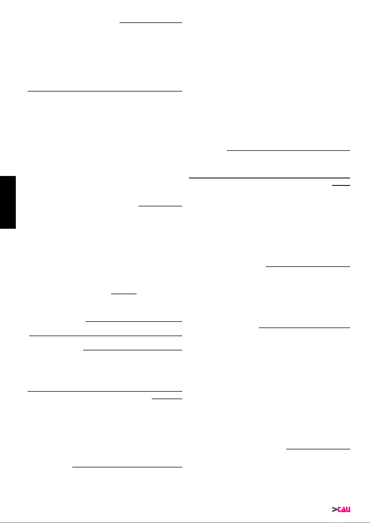
PARTE FINALE DELL’ INSTALLAZIONE
Come prima operazione si tratta di ssare la staffa (A g.16) di
ancoraggio della guida di scorrimento al telaio della basculante
o alla muratura, con viti autoperforanti o tasselli ad espansione,
assicurandosi che sia ben saldo.
Come già indicato nelle prime pagine, vanno rispettate le misure
d’installazione e l’asse della porta basculante in modo da bilanciare
il peso della stessa.
Come seconda operazione (vedi g.17) portare l’impianto in
posizione orrizzontale e segnare i punti nei quali praticare i fori per
il ssaggio delle aste forate di sostegno del motoriduttore e della
guida di scorrimento.
Procedere ora al bloccaggio delle aste forate con i relativi tasselli
ad espansione, assicurandosi che la tenuta sia idonea.
Fissare la staffa B alla porta basculante nella posizione più
prossima al bordo superiore, usando due viti autoperforanti
(g.18a).
Inserire inne la spina motore sulla presa di corrente e vericare
il funzionamento dell’impianto. Ad impianto montato tendere la
catena regolando il dado (C g.18) che agisce sulla vite con una
apposita chiave.
Ora non rimane che procedere alla programmazione della scheda
elettronica; è necessario quindi togliere il carter motore e seguire
le istruzioni riportate nel libretto relativo alla scheda di comando.
INSTALLAZIONE SBLOCCO ESTERNO
Se il garage è cieco installare lo sblocco esterno come in gura
18a.
MANOVRA MANUALE DALL’INTERNO O SBLOCCO
La manovra manuale deve avvenire esclusivamente a porta ferma
e dopo aver tolto l’alimentazione alla centrale elettrica.
DALL’ESTERNO: Se installato lo sblocco esterno, ruotare la
maniglia e agire sulla porta manualmente.
DALL’INTERNO: Tirare il pomello verso il basso e agire sulla porta
manualmente.
NOTA: eseguire un periodico controllo della funzionalità
del meccanismo, eventualmente agire sui dadi di
regolazione della guaina.
IMPIANTO TIPO (g.19)
1_ MOTORIDUTTORE + CENTRALINA
2_ PULSANTIERA *
3_ CASSETTA DI DERIVAZIONE *
4_ ANTENNA + LAMPEGGIANTE *
5_ FOTOCELLULE DI SICUREZZA *
6_ SELETTORE A CHIAVE *
*venduta a parte
SEZIONE CAVI (g.19)
a_ 4x0.5 mm² Fotocellule (RX)
b_ RG58 Antenna
c_ 2x0.5 mm² Lampeggiante-Fotocellule (TX)
d_ 3x0.5 mm² Selettore a chiave
e_ 3x0.5 mm² Pulsantiera
Come per l’impianto elettrico, lo schema riportato in g. 19 è
puramente indicativo ed è compito dell’installatore o dell’acquirente
dotare l’impianto medesimo di tutti gli accorgimenti necessari ad
un suo corretto e funzionale utilizzo, dotandolo inoltre di tutti quei
dispositivi di sicurezza e/o segnalazione necessari al ne di portare
a Norma l’impianto di automazione. Qualora ciò non avvenga
per negligenza dell’installatore o per leggerezza dell’acquirente
nale, la Ditta costruttrice declina ogni responsabilità in merito ad
eventuali danni occorsi a cose e/o persone.
PARTE ELETTRICA
Lo schema dell’impianto elettrico è puramente indicativo e le
sezioni dei cavi fanno riferimento ad un motoriduttore in 24V dc.
Scegliere in ogni caso i percorsi più brevi per le linee dei cavi. Si
consiglia poi di prevedere nell’impianto un interruttore generale,
fuori della portata di persone inadatte, che consenta di togliere
l’alimentazione al motoriduttore in caso di manutenzione o se il
motoriduttore rimane inattivo per un lungo periodo.
Realizzare i collegamenti elettrici come indicato nella g. 19 in
cui viene illustrato un impianto tipo con disposizione e passaggio
dei vari li elettrici, posizionamento delle scatole di derivazione,
pulsantiere e dell’eventuale selettore a chiave e delle fotocellule
a parete. Fatto ciò inserire la spina sulla presa di alimentazione; a
questo punto il motoriduttore è in grado di funzionare.
ITALIANO

9
SKYBOX Series
ADATTATORE PER PORTE BASCULANTI (150BAN)
- INSTALLAZIONE (Venduto a parte)
Il 150BAN deve essere usato per motorizzare porte basculanti a
contrappesi con motorizzazioni mod. SKYBOXE/CE. L’installatore
deve innanzitutto vericare l’idoneità della struttura esistente,
osservando che:
- sia possibile ssare il binario dello SKYBOXE/CE sulla parte
superiore del telaio di sostegno della porta basculante stessa
o sull’architrave appena sopra (se a lo con il telaio), vedi
dettaglio A di g. 20;
- la distanza tra il binario di scorrimento dello SKYBOXE/CE e il
punto più alto raggiunto dalla basculante durante la rotazione
(quota X di g. 22) sia almeno di 1 cm superiore allo spessore
della porta stessa.
Per una corretta installazione procedere come segue:
- posizionare il 150BAN sulla mezzeria della porta, perfettamente
perpendicolare ed a lo con il limite superiore della porta
basculante (B g.21) e ssarlo usando 4/6 viti autoperforanti;
- assemblare il 150BAN come nel dettaglio C di g.21,
ricordandosi di sostituire l’asta forata curva con quella dritta;
- ssare il 150BAN alla slitta, rispettando la quota di 1 cm dal
longherone (D g. 20) e facendo scorrere l’asta forata no a far
combaciare i fori per il ssaggio (E g. 21);
RACCOMANDAZIONI
1_ Integrare la sicurezza del portone conformemente alla
normativa vigente.
2_ Scegliere percorsi brevi per i cavi e tenere separati i cavi di
potenza dai cavi di comando.
3_ In accordo con la normativa europea in materia di sicurezza si
consiglia di inserire un interruttore esterno per poter togliere
l’alimentazione in caso di manutenzione del portone.
4_ Vericare che ogni singolo dispositivo installato sia efciente
ed efcace.
5_ Afggere cartelli facilmente leggibili che informino della
presenza del portone motorizzato.
USO
Si fa’ espresso divieto di utilizzare l’apparecchio per scopi diversi o
in circostanze diverse da quelle menzionate. Si ricorda che siamo
in presenza di un dispositivo automatico e alimentato a corrente,
perciò da usare con precauzione. In particolare , si ammonisce di
:
1_ non toccare l’apparecchio con mani bagnate;
2_ togliere la corrente prima di aprire la scatola comandi e/o
motoriduttore;
3_ non tirare il cavo di alimentazione per staccare la presa di
corrente;
4_ non toccare il motore se non siete sicuri che sia raffreddato;
5_ mettere in movimento il portone solo quando è completamente
visibile ;
6_ tenersi fuori dal raggio di azione del portone se questo è in
movimento: aspettare no a che non sia fermo;
7_ non lasciare che bambini o animali giochino in prossimità del
portone;
8_ non lasciare che bambini o persone inadatte usino il
telecomando o altri dispositivi di azionamento;
9_ effettuare una manutenzione periodica;
10_ in caso di guasto, togliere l’alimentazione e gestire il portone
manualmente solo se possibile e sicuro. Astenetersi da ogni
intervento e chiamare un tecnico autorizzato;
11_ è vietato toccare qualsiasi organo meccanico durante il
funzionamento;
12_ tutto quello che non è espressamente previsto in queste
istruzioni non è permesso.
MANUTENZIONE
Il buon funzionamento dipende anche dallo stato del portone-
basculante: perciò descriveremo brevemente anche le operazioni
da fare per avere un portone sempre efciente.
Attenzione: nessuna persona ad eccezione del manutentore,
che deve essere un tecnico specializzato, deve poter comandare
l’automatismo durante la manutenzione. Si raccomanda perciò di
togliere l’alimentazione di rete, evitando così anche il pericolo di
shock elettrici. Se invece l’alimentazione dovesse essere presente
per talune veriche, si raccomanda di controllare o disabilitare
ogni dispositivo di comando (telecomandi, pulsantiere, etc) ad
eccezione del dispositivo usato dal manutentore.
MANUTENZIONE ORDINARIA
Ciascuna delle seguenti operazioni deve essere fatta quando se
ne avverte la necessità e comunque ogni 6 mesi (ogni 750 cicli di
lavoro).
Portone:
1_ Lubricare i bracci.
Impianto di automazione:
1_ verica funzionamento dispositivi di sicurezza (fotocellule, etc.).
Essi devono essere efcaci in caso di pericolo ed intervenire
secondo le modalità selezionate in fase di installazione;
2_ lubricare la catena;
3_ vericare che la corsia di scorrimento sia pulita e libera da
detriti;
4_ aprire manualmente il portone per tutta la sua corsa
assicurandosi di esercitare uno sforzo sempre inferiore a 150
N (15 kg);
5_ vericare che la porta, durante il moto, non subisca punti
d’attrito;
6_ vericare che la porta, fermata in qualsiasi punto e sbloccata,
non accenni a cadere;
7_ vericare che i collegamenti a vite siano ben stretti.
FREQUENZA: ogni 750 manovre o 6 mesi, pena la decadenza
della garanzia.
MANUTENZIONE STRAORDINARIA O ROTTURE
Se dovessero rendersi necessari interventi non banali su parti
elettromeccaniche , si raccomanda la rimozione della parte dove il
guasto è localizzato per consentire una riparazione in ofcina dai
tecnici della casa madre o da essa autorizzati.
SMALTIMENTO
SKYBOXE/CE è costituio da varie tipologie di materiali e
l’eliminazione di questi va effettuata rispettando le norme vigenti
nei singoli paesi.
Nel caso di demolizione dell’automatismo non esistono particolari
pericoli o rischi derivati dall’automaizone stessa. E’ opportuno, in
caso si desideri effettuare una raccolta differenziata, che i materiali
vengano separati per tipologia (parti elettriche, alluminio, plastica,
ecc.).
ITALIANO

10
SKYBOX Series
STANDARD SYSTEM
Mechanism for operating vertical-opening garage doors: sectionals
doors (g.3), overhead spring-balanced doors (g.4). For doors not
tted with guide rails (g.5), this mechanism can be provided with
an adaptor kit (the door cannot be fully opened) that is not included
in the box. For sectional doors (g.3) a stop must be tted on the
guide rail to block movement during opening.
DESCRIPTION AND MEASUREMENTS TO COMPLY
WITH (g.6-7)
Before starting, make sure the door is correctly balanced and
slides smoothly.
1_ Door header
2_ Ceiling
3_ Bracket
4_ Guide
5_ Slider
6_ Guide xing lug
7_ Gear motor
Before beginning to install the gear motor, some considerations
must be made in order to make each subsequent step easier.
Make sure there is a clearance of at least 40/120 mm between the
ceiling and the highest sliding point of the door (g. 8).
N.B.: if the measure is less than 40/120 mm, it is not
recommended to install it.
In the case of sectional doors, check that the upper guide roller is
in the horizontal part of the guide when the door is closed (g. 8).
Make sure the chain guide is always at the same distance
from the oor when mounting.
Align the chain guide with the overhead door as shown in g. 9. Y4
must be equal to or greater than the thickness of the door (plus 1
cm) to ensure that it doesn’t touch the chain guide when opening.
Important: make sure that the angle formed by the door when
it is fully open (α° g. 8) is greater than 90°. If necessary,
install rubber bumpers on the overhead door.
STANDARD ACCESSORIES (g.10)
TOOLS REQUIRED FOR ASSEMBLY (g.11)
INSTALLING THE GUIDE
1_ Straighten the two tracks as shown in the drawing (g.12).
2_ Slide the coupling so as to join the tracks together (g.13) and
adjust the stroke of the shoe using the 2 supplied plates (detail
A g. 13).
SECURING THE SUPPORTING RODS TO THE GEAR
MOTOR
Prepare to x the gearmotor and track to the ceiling as follows:
- x the omega bracket to one of the perforated rods attached to
the Skybox safety guard (g.14);
- bend the rod so that it can be xed to the ceiling (A g.14);
- similarly, x the second perforated rod to the buttery bracket
halfway along the track and bend it so that it, too, can be xed
to the ceiling (g.15).
FINAL PART OF INSTALLATION
First x the anchor bracket (A g. 16) of the chain guide to the
doorframe or wall with self-tapping screws or expansion bolts,
making sure it is rmly secured.
As described at the beginning of this booklet, observe the
installation measurements and make sure the overhead door is
properly aligned so that its weight is perfectly balanced.
The second thing to do (see g.17) is to move the unit to its
horizontal position and mark the positions of the holes required to
x the perforated rods supporting the gear motor and the guide.
Now secure the perforated rods with the expansion bolts and make
sure they are well fastened.
Fix bracket B to the overhead door, as near as possible to the top
edge, using two self-tapping screws (g.18a).
Lastly, plug in the motor and check that the unit works. After
installation, tighten the chain using a spanner to adjust the nut
(g.18) which acts on the screw.
Then programme the electronic card by removing the motor casing
and following the instructions in the control card handbook.
INSTALLING THE EXTERNAL RELEASE DEVICE
If the garage has no other accesses, install the external release
device as shown in the gure 18a.
MANUAL MANOEUVRE FROM INSIDE OR RELEASE
DEVICE
The manual manoeuvre must be made exclusively with the door
stopped and after disconnecting power from the electrical control
unit.
FROM OUTSIDE: if the external release device is installed, turn
the handle and push the door.
FROM INSIDE: Pull the knob downwards and push the door.
NOTE: from time to time, check that the mechanism
is working correctly, if necessary act on the
sheathing adjustment nuts.
STANDARD SYSTEM (g.19)
1_ GEAR MOTOR + CONTROL UNIT
2_ PUSH BUTTON PANEL *
3_ PULL BOX *
4_ AERIAL + FLASHING LIGHT *
5_ WALL-MOUNTED PHOTOCELLS *
6_ KEY SELECTOR *
*sold separately
CROSS-SECTIONS OF CABLES (g.19)
a_ 4x0.5 mm² Photocells (RX)
b_ RG58 Aerial
c_ 2x0.5 mm² Flashing light-Photocells (TX)
d_ 3x0.5 mm² Key selector
e_ 3x0.5 mm² Push button panel
Similarly to the wiring diagram, the diagram in Fig. 19 is only
approximate. The installer or purchaser must make sure that the
unit is tted with all the devices required to ensure it works correctly
and smoothly, and install all the safety and/or signalling devices
required to ensure it complies with the relative standards. If this
is not done due to the installer’s negligence or the purchaser’s
irresponsibility, the manufacturer declines all liability for damage to
people and/or property.
ELECTRICAL SYSTEM
The wiring diagram of the electrical installation is only indicative
and the cross-sections of the cables refer to a 24Vdc gear motor.
Always choose the shortest routes for the cables. A main switch
should be provided on the system, out of reach of unauthorised
people, allowing power to be disconnected from the gear motor for
maintenance purposes or if the gear motor remains inactive for a
long period of time.
Make the electrical connections as shown in g. 19 which shows
a standard system with the layout of the various wires and the
position of the pull boxes, push button panels, key selector if there
is one and wall-mounted photocells. Then plug in the unit to power
the gear motor.
ADAPTER FOR OVERHEAD DOORS (150BAN) - IN-
STALLATION (Sold separately)
The 150BAN is required to power overhead doors with
counterweights and mod. SKYBOXE/CE motors. The tter must
rst ensure that the existing structure is suitable by checking that:
ENGLISH

11
SKYBOX Series
- the SKYBOXE/CE track can be tted to the upper part of the
doorframe or to the architrave just above it (if this lies ush with
the frame), see pos. A in g. 20;
- the distance between the SKYBOXE/CE sliding track and the
highest point reached by the overhead door during rotation
(distance X in g. 22) is at least 1 cm greater than the thickness
of the door.
Install as follows:
- position the 150BAN in the middle of the door, perfectly
perpendicular and ush with its upper edge (B g.21). Secure
with 4/6 self-tapping screws;
- assemble the 150BAN, see pos. C in g. 21, not forgetting to
replace the curved drilled rod with the straight one;
- x the 150BAN to the slide, keeping at a distance of 1 cm from
the longitudinal member (D g. 20) and sliding the slotted bar
until the holes match the xing holes (E g. 21);
RECOMMENDATIONS
1_ Integrate overhead garage door safety in compliance with
current laws.
2_ Choose short routes for cables and keep power cables
separate from control cables.
3_ An external switch should be tted, in compliance with
European safety standards, in order to disconnect mains
power when servicing the door.
4_ Make sure that each device is in perfect working order.
5_ Put up easy-to-read signs informing people that they are near
a motor-driven door.
USE
It is categorically forbidden to use the equipment for purposes or
in circumstances other than those mentioned herein. Please bear
in mind that this is an electrically powered automatic device which
should therefore be used with caution. In particular:
1_ do not touch the equipment with wet hands;
2_ disconnect the power supply before opening the control box
and/or the gear motor;
3_ do not remove the plug by pulling the lead;
4_ do not touch the motor unless you are sure it is cold;
5_ only operate the door when it is completely visible;
6_ do not approach the door while it is moving: wait until it has
stopped;
7_ do not allow children or animals to play near the door;
8_ do not allow children or unauthorised people to use the remote
control or other control devices;
9_ carry out routine maintenance;
10_ in the event of a fault, disconnect the power supply and
only move the door if it is possible and safe to do so. Do not
attempt to repair the door but call in an authorised technician;
11_ it is forbidden to touch moving parts while the device is
working;
12_ anything not expressly specied in these instructions is
forbidden.
MAINTENANCE
As the performance of the system also depends on the state of
the overhead door, the operations required to keep it in perfect
condition are described below.
Attention: no-one, except for qualied maintenance men, must be
able to use the automatic system during servicing. Switch off the
mains power supply to eliminate the risk of electrocution. If the
power supply must be left on for certain operations, each control
device (remote controls, push button panels, etc.) should be
checked or disabled, except for the one used by the maintenance
man.
ROUTINE MAINTENANCE
Each of the following operations must be carried out when
necessary and always every 6 months (always 750 work cycles).
Door:
1_ Lubricate the hinges.
Automation system:
1_ check the safety devices (photocells, etc.). They must work
properly in dangerous situations and cut in as congured
during installation;
2_ lubricate the chain;
3_ check that the slide way is clean and free from debris;
4_ push the door fully open making sure never to use a force of
more than 150 N (15 kg);
5_ make sure the door moves smoothly;
6_ make sure that the door does not descend when it is stopped
and released at any point;
7_ check that the screw connections are perfectly tight.
FREQUENCY: every 750 manoeuvres or 6 months, failing
which the guarantee lapses.
EXTRAORDINARY MAINTENANCE OR BREAKAGE
If major work on electromechanical parts must be carried out, the
faulty part should be removed and repaired in the workshop by the
manufacturer’s or other authorised technicians.
DISPOSAL
SKYBOXE/CE comprises various types of materials which must be
disposed of in compliance with current legislation.
There are no particular dangers or risks deriving from demolition of
the system. If waste sorting is required, the components should be
grouped by type of material (electrical, aluminium, plastic, etc.).
ENGLISH

12
SKYBOX Series
TYPISCHE ANLAGE
Automatisierung für die automatische Öffnung eines sich vertikal
bewegenden Garagentors: Sektionaltoren (Abb. 3), Kipptoren mit
Feder ausgewuchtet sind (Abb. 4). Für führungslose Tore (Abb.
5) kann die Automatisierung mit einem Adapterkit geliefert werden
(das Tor wird sich nicht ganz öffnen), der in der Verpackung
nicht enthalten ist. Für Sektionaltore (Abb. 3) ist es Picht, eine
Feststellvorrichtung in die Führung einzubauen, um den Torlauf in
Öffnung zu blockieren.
BESCHREIBUNG UND EINZUHALTENDE MAßE (Abb.6-
7)
Bevor man beginnt, muss sichergestellt werden, dass das Tor
richtig ausgeglichen ist und bestens und ohne Reibungen auf der
gesamten Laufstrecke funktioniert.
1_ Fester Torteil
2_ Decke
3_ Einspannbügel
4_ Gleitführung
5_ Gleitbacke
6_ Führungshalterung
7_ Getriebemotor
Vor der Installation des Getriebemotors werden einige Hinweise
gegeben, um jede nachfolgende Arbeitsphase einfacher zu
machen.
Sicherstellen, dass zwischen Decke und dem höchsten Gleitpunkt
des Tors ein Mindestabstand von 40/120 mm vorhanden ist (Abb.
8).
NB: falls das Maß kleiner als 40/120 mm ist, wird von der
Installation abgeraten.
Bei den Sektionstoren ist zu sicherzustellen, dass sich die
obere Führungsrolle bei geschlossenem Tor im horizontalen
Führungsbereich bendet (Abb. 8)
Wichtig: die Gleitführung muss so montiert sein, dass ihr
Abstand vom Fußboden immer gleich ist.
Die Gleitführung muss mit der Schwingtür auf einer Achse
positioniert werden, wie in Abb. 9 gezeigt. Das angegebene Maß
Y4 muss gleich oder größer als die Türdicke (plus 1 cm) sein,
damit die Tür während der Öffnung die Gleitführung nicht berührt.
Wichtig: prüfen, dass der Winkel, der sich bei ganz geöffnetem
Tor bildet (α° Abb. 8), über 90° beträgt. Ggf. Gummistopfen am
Schwingtor anbringen.
MITGELIEFERTES ZUBEHÖR (Abb.10)
WERKZEUGE, DIE FÜR DIE MONTAGE NÖTIG SIND
(Abb.11)
MONTAGE DER GLEITFÜHRUNG
1_ Die beiden Schienen wie auf der Zeichnung gezeigt
gleichrichten (Abb.12).
2_ Die Verbindung gleiten lassen, so dass die Schienen vereint
sind (Abb.13) und den Lauf der Gleltbacke mit Hilfe der 2
mitgelieferten Plättchen regulieren (Teil A, Abb. 13).
BEFESTIGUNG DER TRAGSTANGEN AM GETRIEBE-
MOTOR
Die Befestigung des Getriebemotors und der Schiene an der
Decke wie folgt vorbereiten:
- den Omega-Bügel an einer der gelochten Stangen am
Gehäuse von Skybox befestigen (Abb.14);
- die Stange biegen, damit sie an der Decke befestigt werden
kann (A Abb.14);
- die zweite gelochte Stange wie die erste am Bügel auf
halber Schiene befestigen, dann wie vorher erwähnt für die
Deckenmontage biegen (Abb.15).
ENDTEIL DER INSTALLATION
Als erstes muss der Ankerbügel (A Abb.16) der Gleitführung
mit selbstbohrenden Schrauben oder Spreizdübeln am
Schwingtorrahmen oder an der Mauer gut befestigt werden.
Wie auf den ersten Seiten angegeben, sind die Installationsmaße
und die Achse der Schwingtür zu beachten, so dass das Gewicht
der Tür ausgeglichen ist.
Als zweites (siehe Abb.17) die Anlage in horizontale Stellung
bringen und die Punkte aufzeichnen, an denen die Löcher zur
Befestigung der Lochstangen zum Halten des Getriebemotors und
der Gleitführung gebohrt werden müssen.
Nun die Lochstangen mit den jeweiligen Spreizdübeln blockieren
und sicher stellen, dass sie gut befestigt sind.
Den Bügel B mit zwei selbstschneidenden Schrauben so nah
wie möglich an der oberen Kante des Schwingtors anbringen
(Abb.18a).
Dann den Motorstecker in die Stromsteckdose einstecken und den
Betrieb der Anlage überprüfen. Nach der Montage der Anlage die
Kette spannen, indem die Mutter (C Abb.18), die auf die Schraube
einwirkt, mit einem Schlüssel reguliert wird.
Als letztes die elektronische Steuerkarte programmieren. Dazu das
Motorgehäuse entfernen und die Anweisungen in der Anleitung
der Steuerkarte befolgen.
INSTALLATION DER EXTERNEN ENTRIEGELUNG
Falls die Garage keine anderen Zugangstüren oder Fenster hat,
die externe Entriegung gemäß der Abbildung 18a installieren.
MANUELLE BEWEGUNG DES TORS VON INNEN ODER
ENTRIEGELUNG
Die manuelle Bewegung darf ausschließlich bei stehendem Tor
und nach Abschalten der Versorgung zur Steuerung ausgeführt
werden.
VON AUßEN: Falls die externe Entriegelung installiert ist, den Griff
drehen und das Tor von Hand betätigen.
VON INNEN: Den Knauf nach unten ziehen und das Tor von Hand
betätigen.
ANMERKUNG: Die Funktionstüchtigkeit des Mechanismus
regelmäßig überprüfen, ggf. die
Verstellmuttern des Mantels betätigen.
TYPISCHE ANLAGE (Abb.19)
1_ GETRIEBEMOTOR + STEUERUNG
2_ DRUCKKNOPFTAFEL *
3_ ABZWEIGKASTEN
4_ ANTENNE + BLINKLEUCHTE *
5_ PHOTOZELLEN AN MAUER *
6_ SCHLÜSSELTASTER *
*gesondert verkauft
KABELSCHNITT (Abb.19)
a_ 4x0.5 mm² Photozellen (RX)
b_ RG58 Antenne
c_ 2x0.5 mm² Blinkleuchte-Photozellen (TX)
d_ 3x0.5 mm² Schlüsseltaster
e_ 3x0.5 mm² Druckknopftafel
Wie für die elektrische Anlage, ist der Plan in Abb. 19 nur als
Hinweis zu betrachten, und es ist Aufgabe des
Installateurs oder des Käufers, die Anlage mit allen Vorrichtungen
auszustatten, die für ihren korrekten und funktionellen Gebrauch
notwendig sind, weiterhin muss sie mit allen Sicherheits- und/oder
Warnvorrichtungen ausgestattet werden, die für eine normgerechte
Gestaltung der Automatisierung erforderlich sind. Falls dies wegen
Fahrlässigkeit des Installateurs oder des Endkunden nicht erfolgt,
so lehnt der Hersteller jede diesbezügliche Haftung für Personen-
und/oder Sachschäden ab.
ELEKTRISCHER TEIL
Der Plan der elektrischen Anlage dient nur als Hinweis; die
Kabelschnitte beziehen sich auf einen 24 Vdc Getriebemotor.
DEUTSCH

13
SKYBOX Series
Zum Verlegen der Kabel immer die kürzesten Strecken wählen.
Weiterhin sollte die Anlage mit einem Hauptschalter ausgerüstet
werden, der sich außerhalb der Reichweite Unzuständiger
bzw. Ungeeigneter bendet und mit dem die Versorgung zum
Getriebemotor bei Wartung oder längerem Stillstand abgeschaltet
werden kann.
Die elektrischen Anschlüsse gemäß Abb.19 ausführen. Auf ihr
ist eine typische Anlage mit Anordnung und Durchführung der
verschiedenen Drähte, Stellung der Abzweigdosen, Druckknopftafel
und des eventuellen Schlüsseltasters und der Photozellen an
mauer gezeigt. Danach den Stecker in die Steckdose stecken; der
Getriebemotor kann nun funktionieren.
ADAPTER FÜR SCHWINGTORE (150BAN) - (Gesondert
verkauft)
Der Adapter 150BAN muss für die Automatisierung von
Schwingtüren mit Gegengewicht mit Motoren Mod. SKYBOXE/CE
benutzt werden. Als erstes muss der Installateur prüfen, ob die
vorhandene Struktur geeignet ist, insbesondere:
- ob es möglich ist, die Schiene des SKYBOXE/CE an der
Oberseite des Schwingtürrahmens oder am Türsturz gleich
darüber (falls mit dem Rahmen abschließend) zu befestigen
– siehe Detail A in Abb. 20;
- ob der Abstand zwischen Gleitschiene von SKYBOXE/CE und
der höchsten Stelle, die von der Schwingtür bei ihrer Drehung
erreicht wird (Maß X in Abb. 22), mindestens 1 cm größer als
die Tordicke ist.
Für eine korrekte Installation wie folgt vorgehen:
- den Adapter 150BAN an der Türhälfte anbringen, so dass er
rechtwinklig zur Schwingtür ist und mit dem oberen Ende der
Schwingtür abschließt (B, Abb. 21); mit 4/6 selbstbohrenden
Schrauben befestigen;
- den 150BAN zusammenbauen, wie in C auf Abb. 21 gezeigt,
dabei die gebogene gelochte Stange mit der geraden
ersetzen;
- den 150BAN am Schlitten befestigen, dabei das Maß 1 cm
vom Längsträger beachten (D, Abb. 20) und die gelochte
Stange gleiten lassen, bis die Bohrungen für die Befestigung
zusammentreffen (E, Abb. 21);
RATSCHLÄGE
1_ Die Sicherheit des Tors gemäß den gültigen Vorschriften
integrieren.
2_ Die kürzesten Strecken für die Kabel wählen und die
Leistungskabel von den Steuerkabeln getrennt halten.
3_ In Vereinbarung mit den europäischen Sicherheitsvorschriften
wird empfohlen, einen externen Schalter zu installieren, damit
die Versorgung im Falle von Wartung des Tors abgeschaltet
werden kann.
4_ Prüfen, ob jede einzelne installierte Vorrichtung efzient und
wirksam ist.
5_ Gut leserliche Schilder anbringen, die über das Vorhandensein
des motorbetriebenen Tors informieren.
BEDIENUNG
Es ist ausdrücklich verboten, das Gerät zu anderen Zwecken oder
unter anderen Umständen als erwähnt zu verwenden. Wir erinnern
daran, dass man hierbei mit einer automatischen, mit Strom
gespeisten Vorrichtung zu tun hat, daher ist Vorsicht geboten.
Insbesondere:
1_ das Gerät nicht mit nassen Händen berühren;
2_ den Strom abschalten, bevor das Gehäuse und/oder der
Getriebemotor geöffnet wird;
3_ nicht am Stromkabel ziehen, um dieses von der Steckdose
abzutrennen;
4_ den Motor erst berühren, wenn er abgekühlt ist;
5_ das Tor nur in Bewegung setzen, wenn es ganz sichtbar ist;
6_ außerhalb des Aktionskreises des Tors bleiben, wenn sich
dieses bewegt, und warten, bis es steht;
7_ Kinder oder Tiere nicht in Tornähe spielen lassen;
8_ Kindern oder Ungeeigneten nicht die Fernbedienung oder
sonstige Betätigungsvorrichtungen benutzen lassen;
9_ eine regelmäßige Wartung ausführen;
10_ im Falle eines Defekts die Versorgung abschalten und das
Tor nur falls möglich und sicher von Hand bewegen. Keine
Eingriffe selbst ausführen und einen autorisierten Techniker
rufen;
11_ die Berührung mechanischer Elemente während des Betriebs
ist untersagt;
12_ alles nicht ausdrücklich in diesen Anleitungen vorgesehene
ist unzulässig.
WARTUNG
Ein einwandfreier Betrieb hängt auch vom Zustand des
Schwingtors ab: deshalb werden wir die Arbeiten, die zu tun sind,
damit das Tor immer efzient ist, kurz beschreiben.
Achtung: niemand mit Ausnahme des Wartungsmannes, der
ein Fachtechniker sein muss, ist befugt, die Automatisierung
während der Wartung zu steuern. Es wird daher empfohlen,
die Netzstromversorgung abzuschalten, wodurch auch die
Stromschlaggefahr vermieden wird. Falls die Versorgung dagegen
für bestimmte Überprüfungen eingeschaltet sein muss, so sind alle
Steuervorrichtungen (wie Fernbedienungen, Druckknopftafeln,
usw.) mit Ausnahme der vom Wartungsmann benutzten
Vorrichtung zu deaktivieren.
GEWÖHNLICHE WARTUNG
Jede der folgenden Arbeiten muss wenn nötig und mindestens alle
6 Monate gemacht werden (immer ungefähr 750 Arbeitszyclen).
Tor:
1_ Die Arme schmieren;
Automatisierungsanlage:
1_ Überprüfung der Funktionsweise der Sicherheitsvorrichtungen
(Photozellen, usw.). Sie müssen bei Gefahr wirksam sein und
auf die Arten und Weisen eingreifen, die bei der Installation
gewählt worden sind;
3_ prüfen, ob die Gleitführung sauber und frei von Schmutzteilchen
ist;
4_ das Tor auf seiner ganzen Laufstrecke von Hand öffnen und
sicher stellen, dass dabei immer eine Kraft unter 150 N (15 kg)
ausgeübt wird;
5_ prüfen, ob das Tor während der Bewegung keinen Reibungen
ausgesetzt ist;
6_ prüfen, ob das Tor, wenn an einer beliebigen Stelle angehalten
und entriegelt, nicht nach unten geht;
7_ prüfen, ob die Schraubverbindungen fest angezogen sind.
HÄUFIGKEIT: alle 750 Bewegungen oder alle 6 Monate, an-
dernfalls wird die Garantie ungültig.
AUßERGEWÖHNLICHE WARTUNG ODER DEFEKTE
Falls schwierigere Arbeiten an elektromechanischen Teilen
erforderlich sein sollten, wird die Entfernung des defekten Teils
empfohlen, damit eine Reparatur in der Werkstatt durch die
Herstellertechniker oder autorisierte Techniker erfolgen kann.
ENTSORGUNG
SKYBOXE/CE besteht aus unterschiedlichen Werkstoffen,
deren Entsorgung nach den Gesetzen erfolgen muss, die in den
einzelnen Ländern gültig sind.
Im Falle eines Abbruchs der Automatisierung gibt es keine
besonderen Gefahren oder Risiken aufgrund der Automatisierung
selbst. Im Falle von differenzierter Müllabfuhr sollten die Werkstoffe
nach ihrer Typik sortiert werden (elektrische Teile, Aluminium,
Plastik, usw.).
DEUTSCH
14
SKYBOX Series
INSTALLATION TYPE
Automatisme qui permet l’ouverture automatique de la porte
d’un garage à mouvement vertical : portes sectionnelles (g.3),
portes basculantes équilibrées à ressort (g.4). Pour les portes
dépourvues de glissières (g.5), l’automatisme peut être complété
par un Kit d’adaptation (la porte ne parvient pas à s’ouvrir
complètement) qui n’est pas contenu dans la boîte. Pour les portes
sectionnelles (g.3) il est obligatoire de monter dans la glissière
une butée pour bloquer la course en ouverture.
DESCRIPTION ET MESURES À RESPECTER (g.6-7)
Avant de commencer, s’assurer que la porte a été bien équilibrée
et qu’elle fonctionne parfaitement, sans points de friction sur toute
la course.
1_ Partie xe porte
2_ Plafond
3_ Étrier de xation
4_ Rail de guidage
5_ Patin
6_ Support rail
7_ Motoréducteur
Avant de procéder à l’installation du motoréducteur, il faut faire
quelques considérations pour faciliter les phases successives.
Contrôler qu’il y ait un espace de 40/120 mm au minimum entre le
plafond et le point le plus haut de glissement du portail (g. 8).
N.B. : si la mesure est inférieure à 40/120 mm, il est déconseillé
d’effectuer l’installation.
Dans les portails sectionnaux vérier que le rouleau de guidage
supérieur se trouve dans la partie horizontale de la guide à portail
fermé (g. 8).
Il est important que le rail de guidage soit monté de manière à
être toujours à la même distance par rapport au sol.
Le rail de guidage doit être positionné dans l’axe avec la porte
basculante comme dans la g. 9. La mesure Y4 indiquée doit être
identique ou supérieure à l’épaisseur de la porte (majorée d’1
cm) pour éviter que la porte touche le rail de guidage en phase
d’ouverture.
Important : vérier que, avec la porte complètement ouverte,
l’angle qui se forme (α° g. 8) est supérieur à 90°. Appliquer
éventuellement des bouchons en caoutchouc sur la porte
basculante.
ACCESSOIRES FOURNIS (g.10)
OUTILS NÉCESSAIRES POUR LE MONTAGE (g.11)
MONTAGE DU RAIL DE GUIDAGE
1_ Redresser les deux rails comme sur le dessin (g.12).
2_ Faire coulisser le joint de manière à unir les rails (g.13) et
régler la course du patin à l’aide des 2 platines fournies (pos.
A g. 13).
FIXATION DES BARRES DE SUPPORT AU MOTORÉ-
DUCTEUR
Préparer la xation du motoréducteur et du rail au plafond en
procédant de la façon suivante :
- xer l’étrier oméga à l’une des barres perforées en appui sur le
carter du Skybox (g.14) ;
- plier la barre pour permettre la xation au plafond (A g.14) ;
- xer, en procédant comme pour la première, la deuxième barre
perforée à l’étrier au milieu du rail, en la pliant ensuite comme
la précédente pour la xation au plafond (g.15).
PARTIE FINALE DE L’ INSTALLATION
La première opération consiste à xer l’étrier (A g.16) de xation
du rail de guidage au châssis xe de la porte basculante ou à la
maçonnerie, avec des vis autotaraudeuses ou des chevilles à
expansion, en s’assurant qu’il est solidement xé.
Comme nous le précisons dans les premières pages, il faut
respecter les mesures d’installation et l’axe de la porte basculante
de manière à équilibrer le poids de la porte.
La deuxième opération (voir g.17) consiste à porter l’installation
en position horizontale et à marquer les points dans lesquels
percer les trous pour la xation des barres perforées de support du
motoréducteur et du rail de guidage.
Procéder maintenant au blocage des barres perforées avec les
chevilles à expansion, en s’assurant qu’elles sont bien xées.
Fixer l’étrier B à la porte basculante le plus près possible du bord
supérieur, en utilisant deux vis autotaraudeuses (g.18a).
Brancher enn la che électrique du moteur dans la prise de
courant et vérier le fonctionnement de l’installation. Une fois
l’installation montée, tendre la chaîne en réglant l’écrou (C g.18)
qui agit sur la vis avec une clé adaptée.
Il ne reste maintenant qu’à procéder à la programmation de la
carte électronique ; pour cela, il faut démonter le carter du moteur
et suivre les instructions gurant dans le livret relatif à la carte de
commande.
INSTALLATION DÉBLOCAGE EXTÉRIEUR
Si le garage est sans autre issue installer le déblocage extérieur
comme sur la gure 18a.
MANŒUVRE MANUELLE DE L’INTÉRIEUR OU DÉBLO-
CAGE
La manœuvre manuelle doit être effectuée exclusivement avec
la porte fermée et après avoir coupé l’alimentation de l’armoire
électrique.
DE L’EXTÉRIEUR : Si le déblocage extérieur a été installé, tourner
la poignée et agir manuellement sur la porte.
DE L’INTÉRIEUR : Tirer la poignée vers le bas et agir manuellement
sur la porte.
NOTE : effectuer un contrôle périodique du bon
fonctionnement du mécanisme, agir éventuellement
sur les écrous de réglage de la gaine.
INSTALLATION TYPE (g.19)
1_ MOTORÉDUCTEUR + ARMOIRE DE COMMANDE
2_ TABLEAU DE COMMANDE *
3_ BOÎTIER DE DÉRIVATION *
4_ ANTENNE + CLIGNOTANT *
5_ PHOTOCELLULES MURALES *
6_ SÉLECTEUR À CLÉ *
*vendu à part
SECTION DES CÂBLES (g.19)
a_ 4x0,5 mm² Photocellules (RX)
b_ RG58 Antenne
c_ 2x0,5 mm² Clignotant-Photocellules (TX)
d_ 3x0,5 mm² Sélecteur à clé
e_ 3x0.5 mm² Tableau de commande
Comme pour l’installation électrique, le schéma de la g. 19
est purement indicatif et l’installateur ou l’acheteur sont tenus
de prendre toutes les mesures nécessaires pour assurer une
utilisation correcte et fonctionnelle et de doter l’installation de tous
les dispositifs de sécurité et/ou signalisation nécessaires pour que
l’automatisme soit conforme aux normes. Si ces conditions ne sont
pas assurées, que ce soit à cause de la négligence de l’installateur
ou de la légèreté de l’acheteur nal, le Constructeur décline toute
responsabilité pour les éventuels dommages pouvant survenir aux
choses et/ou aux personnes.
PARTIE ÉLECTRIQUE
Le schéma de l’installation électrique est purement indicatif et les
sections des câbles se réfèrent à un motoréducteur fonctionnant à
24V cc. Choisir dans tous les cas les parcours les plus brefs pour
les lignes des câbles. Il est conseillé de prévoir dans l’installation un
interrupteur général, hors de la portée de personnes inadaptées,
permettant de couper l’alimentation du motoréducteur en cas de
maintenance ou si le motoréducteur reste inactif pendant une
longue période.
FRANCAIS

1
ISTRUZIONI ED AVVERTENZE DESTINATE ALL’UTILIZZATORE DELL’AUTOMAZIONE
COMPLIMENTI per aver scelto per la vostra automazione un prodotto Tau!
Tau S.r.l. produce componenti per l’automazione di cancelli, porte, barriere, serramenti: motoriduttori, centrali di comando, radiocomandi, lampeggianti,
fotocellule e accessori.
I prodotti Tau sono realizzati solo con materiali e lavorazioni di qualità e, come azienda, siamo alla costante ricerca di soluzioni innovative che
semplichino sempre più l’utilizzo delle nostre apparecchiature, curate sotto ogni aspetto (tecnico, estetico ed ergonomico): nella grande gamma Tau il
vostro installatore può scegliere il prodotto che meglio soddisfa le vostre esigenze.
Tau però non produce la vostra automazione che, invece, è il risultato di un’opera di analisi, di valutazione, di scelta dei materiali e realizzazione
dell’impianto eseguita dal vostro installatore di ducia.
Ogni automazione, pertanto, è unica e solo il vostro installatore può eseguire un impianto secondo le vostre esigenze (in quanto dotato dell’esperienza
e della professionalità necessarie), sicuro ed afdabile nel tempo; e soprattutto a regola d’arte, rispondente cioè alle normative in vigore.
Un impianto di automazione è una bella comodità, oltre che un valido sistema di sicurezza e, con poche, semplici attenzioni, è destinato a durare negli
anni.
Anche se l’automazione in vostro possesso soddisfa il livello di sicurezza richiesto dalle normative, questo non esclude l’esistenza di un “rischio residuo”,
cioè la possibilità che si possano generare situazioni di pericolo, dovute ad un utilizzo incosciente e/o errato. Per questo motivo riportiamo alcuni consigli
sui comportamenti da tenere per evitare ogni inconveniente:
- Al primo utilizzo: chiedete al vostro installatore di spiegarvi l’origine dei rischi residui e leggete il presente manuale di istruzioni ed avvertenze per
l’utilizzatore consegnatovi dall’installatore. Conservate il manuale per qualsiasi problema futuro e ricordatevi di consegnarlo ad un eventuale nuovo
proprietario dell’impianto.
- L’impianto di automazione esegue fedelmente i vostri comandi: un uso incosciente e/o improprio può divenire pericoloso. Evitate quindi di
azionare l’automazione quando nel suo raggio d’azione si trovino persone, animali e/o cose.
- NON È UN GIOCO! Fate in modo che i bambini non giochino in prossimità dell’impianto e tenete i telecomandi fuori della loro portata.
- Anomalie: ad ogni comportamento anomalo dell’impianto, togliete l’alimentazione elettrica all’automazione ed eseguite lo sblocco manuale (come
da gura). Evitate qualsiasi intervento personale e chiamate il vostro installatore: una volta sbloccato, l’impianto funzionerà manualmente come
prima dell’installazione.
- Manutenzione: per durare nel tempo e funzionare in completa sicurezza, come qualsiasi altro macchinario, l’impianto necessita di una periodica
manutenzione. Stabilite insieme al vostro installatore i tempi di tale manutenzione. Tau consiglia un intervento ogni 6 mesi per un normale uso
domestico, che può variare in funzione dell’intensità d’uso (sempre ogni 3000 cicli di lavoro).
N.B. Qualsiasi tipo di intervento (controllo, manutenzione e/o riparazione) deve essere eseguito solo da personale qualicato.
- Non modicare l’impianto, nè i relativi parametri di programmazione e di regolazione: la responsabilità è dell’installatore.
N.B. Il collaudo nale, le manutenzioni periodiche e le eventuali riparazioni devono essere documentate (negli appositi spazi) da chi le esegue
e i documenti conservati dal proprietario dell’impianto (IN CASO DI MANCATA DOCUMENTAZIONE LA GARANZIA DECADE).
- Smaltimento: al termine della vita dell’impianto assicuratevi che lo smantellamento venga eseguito da personale qualicato e che i materiali
vengano riciclati o smaltiti secondo le norme valide a livello locale.
- - -- - - - - - - - - - - - - - - - - - - - - - - - - - - - - - - - - - - - - - - - - - - - - - - - - - - - - - - - - - - - - - - - - - - - - - - - - - - - - - - - - - - - - - - - - - - - - -
Tirare il pomello verso il basso e agire sulla porta manualmente. Ruotare la maniglia e agire sulla porta manualmente.
La manovra manuale deve essere eseguita SOLO a porta ferma e DOPO aver tolto l’alimentazione alla centrale elettrica.
Nota: se il vostro impianto è dotato di un telecomando che dopo qualche tempo vi sembra funzionare peggio, oppure non funzionare
affato, potrebbe semplicemente dipendere dall’esaurimento della pila (a seconda del tipo, possono trascorrere diversi mesi no a 2/3
anni). Ve ne potete accorgere dal fatto che la spia di conferma della trasmissione è debole, oppure si accende solo per un breve istante.
Prima di rivolgervi all’installatore provate a scambiare la pila con quella di un altro trasmettitore eventualmente funzionante: se questa
fosse la causa dell’anomalia, sarà sufciente sostituire la pila con un’altra dello stesso tipo.
Nel caso voleste aggiungere nella vostra casa un nuovo tipo di automazione, rivolgendovi allo stesso installatore e alla Tau vi garantirete,
oltre che la consulenza di uno specialista e i prodotti più evoluti del mercato, il migliore funzionamento e la massima compatibilità delle
automazioni.
Vi ringraziamo per aver letto queste raccomandazioni, e vi auguriamo la massima soddisfazione dal vostro nuovo impianto: per ogni tipo
di esigenza rivolgetevi con ducia al vostro installatore.
Italiano

2
Pull the knob downwards and push the door. Turn the handle and push the door.
The manual manoeuvre must ONLY be done with the door stopped and AFTER disconnecting power from the electrical control unit.
N.B.: if your remote control unit (if supplied) starts working badly after a time, or does not work at all, the batteries may be at (they can last from
several months to 2/3 years depending on what type is used). This can be seen from the fact that the transmission conrmation LED gets dimmer
or only turns on for brief moments. Before contacting your tter, try exchanging the battery with one from a good transmitter: if this is the reason
for the fault, simply replace the battery with another one of the same type.
If you wish to add a new automated system to your house, contact your tter and we at Tau to have the advice of a specialist, the most developed
products on the market, best operation and maximum automation compatibility.
Thank you for reading these suggestions and we trust you are fully satised with your new system: please contact your tter for any further
requirements.
English
INSTRUCTIONS AND WARNINGS FOR AUTOMATIC SYSTEM USERS
CONGRATULATIONS on choosing a Tau product for your automation system!
Tau S.r.l. produces components for automatic gates, doors, barriers and shutters. These include gear motors, control units, radio control devices, ashing
lights, photocells and accessories.
Tau products are exclusively made with top quality materials and processes and, as a company, we constantly research and develop innovative solutions
in order to make our equipment increasingly easier to use. We also pay great attention to all details (technology, appearance and ergonomics). The
extensive Tau range makes it possible for your tter to choose the product which best meets your requirements.
Tau, however, does not produce your automated system as this is the outcome of a process of analysis, evaluation, choice of materials and installation
performed by your tter.
Each automated system is unique, therefore, and only your tter has the experience and professionalism required to create a system that is tailor-made
to your requirements, featuring long-term safety and reliability, and, above all, professionally installed and compliant with current regulations.
An automated system is handy to have as well as being a valid security system. Just a few, simple operations are required to ensure it lasts for years.
Even if your automated system satises regulatory safety standards, this does not eliminate “residue risks”, that is, the possibility of dangerous situations
being generated, usually due to irresponsible and/or incorrect use. For this reason we would like to give you some suggestions on how to avoid these
risks:
- Before using the system for the rst time: ask your tter to explain how residue risks can arise and read the instructions and warnings in the user
handbook that your tter will have given you. Keep this manual for future use and, if you should ever sell your automated system, hand it over to the
new owner.
- Your automated system carries out your commands to the letter: irresponsible and/or incorrect use may cause it to become dangerous. Do not
use the system if people, animals and/or objects enter its operating area.
- IT IS NOT A TOY! Make sure children do not play near the system and keep the remote control device out of their reach.
- Faults: If you notice any abnormal behaviour, disconnect the system from the power supply immediately and perform the manual release operation
(see gure). Do not attempt to repair the door but call in your tter: the system will operate manually as it did before installation.
- Maintenance: to ensure long life and totally safe operation, the system required routine maintenance, just like any other piece of machinery.
Establish maintenance times together with your tter. Tau recommends a frequency of 6 months for normal domestic installations but this may vary
depending on the intensity of use (always every 3000 work cycles).
N.B.: All controls, maintenance work and/or repairs may only be carried out by qualied personnel.
- Do not modify the plant or the relative programming and adjustment parameters: your tter will see to that.
N.B. Final testing, routine maintenance and any repairs must be documented by the tter (in the relative spaces) and such documents kept
by the owner of the system (IF THE DOCUMENTS ARE NOT PRODUCED, THE WARRANTY WILL EXPIRE).
- Disposal: At the end of system life, make sure that it is demolished by qualied personnel and that the materials are recycled or disposed of
according to local regulations.

3
Den Knauf nach unten ziehen und das Tor von Hand betätigen. Den Griff drehen und das Tor von Hand betätigen.
Die manuelle Bewegung darf AUSSCHLIESSLICH bei stehendem Tor und NACH Abschalten der Versorgung zur Steuerung ausgeführt
werden.
Anmerkung: wenn eine Fernbedienung zu Ihrer Anlage gehört, die nach einer bestimmten Zeit schlechter oder gar nicht funktioniert, sollten Sie die
Batterie kontrollieren, die ganz einfach leer sein könnte (je nach Typ, kann die Batterie mehrere Monate bis 2-3 Jahre dauern). Sie können das am
Leuchtmelder bemerken, der die Übertragung bestätigt und nur schwach oder ganz kurz aueuchten wird. Tauschen Sie die Batterie mit der eines
anderen, funktionierenden Senders aus, bevor Sie sich an den Installateur wenden: falls die Ursache der Betriebsstörung eine leere Batterie sein sollte,
genügt es, diese mit einer anderen gleichen Typs zu ersetzen.
Falls Sie Ihrem Haus eine weitere neue Automatisierung hinzufügen wollen, werden Sie sich bei Ihrem Installateur und bei Tau neben der Beratung
eines Fachmanns die fortgeschrittensten Produkte garantieren, die es auf dem Markt gibt, mit bestem Betrieb und maximaler Kompatibiltät der
Automatisierungen.
Wir danken Ihnen, dass Sie diese Hinweise gelesen haben und wünschen Ihnen volle Zufriedenheit mit Ihrer neuen Anlage. Wenden Sie sich für jeden
Bedarf vertrauensvoll an Ihren Installateur.
Deutsch
ANWEISUNGEN UND HINWEISE FÜR DEN BENUTZER DER AUTOMATISIERUNG
WIR GRATULIEREN IHNEN zur Wahl eines Tau Produktes für Ihre Automatisierung!
Tau S.r.l. stellt Komponenten für die Automatisierung von Toren, Türen, Schranken und Fenstern her: Getriebemotoren, Steuerzentralen,
Funksteuerungen, Blinkleuchten, Fotozellen und Zubehör.
Die Tau Produkte werden nur mit Materialien und Bearbeitungen hoher Qualität hergestellt, und unsere Firma ist auf der ständigen Suche nach
innovativen Lösungen, mit denen die Benutzung unserer Apparaturen, die in jeder Hinsicht (Technik, Aussehen und Ergonomie) besonders gepegt
sind, immer einfacher wird: unter dem großen Tau Sortiment kann Ihr Installateur das Produkt auswählen, das Ihrem Bedarf am besten entspricht.
Tau ist aber nicht der Hersteller Ihrer Automatisierung, die dagegen das Ergebnis des Werks Ihres Vertrauensinstallateurs ist, der sich mit den
notwendigen Untersuchungen und Bewertungen, der Wahl der Materialien und der Verwirklichung die Anlage beschäftigen wird.
Jede Automatisierung ist daher einzigartig und nur Ihr Installateur kann eine Anlage ausführen, die Ihrem Bedarf entspricht (er besitzt die notwendige
Erfahrung und Professionalität), die sicher und auf Zeit zuverlässig und vor allem fachgerecht ist und mit den gültigen Vorschriften übereinstimmt.
Eine Automatisierungsanlage ist etwas wirklich bequemes, aber auch ein gutes Sicherheitssystem, und mit ein paar einfachen Maßnahmen wird sie
jahrelang dauern.
Auch wenn Ihre Automatisierung dem Sicherheitsniveau entspricht, das von den Vorschriften gefordert wird, schließt dies das Vorhandensein eines
„Restrisikos” nicht aus, bzw. der Möglichkeit, dass Gefahren aufgrund eines fahrlässigen und/oder falschen Gebrauchs erzeugt werden können. Aus
diesem Grund geben wir hier einige Verhaltensweisen an, um diese möglichen Restrisiken zu vermeiden:
- Bei der ersten Benutzung: bitten Sie Ihren Installateur, Ihnen den Ursprung der Restrisiken zu erklären, und lesen Sie die vorliegenden
Anweisungen und Hinweise für den Benutzer, die Ihnen vom Installateur übergeben werden. Bewahren Sie die Anleitung für zukünftige Probleme
auf, und übergeben Sie diese ggf. dem neuen Besitzer der Anlage.
- Die Automatisierungsanlage folgt getreu Ihren Befehlen: ein fahrlässiger und/oder unsachgemäßer Gebrauch kann gefährlich sein. Betätigen
Sie daher die Automatisierung nicht, wenn sich Personen, Tiere und/oder Gegenstände in ihrem Aktionskreis benden.
- SIE IST KEIN SPIEL! Lassen Sie Kinder nicht in der Nähe der Anlage spielen und halten Sie die Fernbedienungen außer deren Reichweite.
- Störungen: schalten Sie bei jedem ungewöhnlichen Verhalten der Anlage die Stromversorgung zur Automatisierung ab und entriegeln Sie von
Hand (siehe Abbildung). Vermeiden Sie jeden persönlichen Eingriff und rufen Sie Ihren Installateur: nach dem Entriegeln wird die Anlage von Hand
funktionieren, wie vor der Installation.
- Wartung: um zu dauern und ganz sicher zu funktionieren, bedarf die Anlage wie jede andere Maschine einer periodischen Wartung. Legen Sie
die Wartungszeiten zusammen mit Ihrem Installateur fest. Tau empehlt für den normalen Hausgebrauch eine Wartung alle 6 Monate, was je nach
Gebrauchshäugkeit unterschiedlich sein kann (immer ungefähr 3000 Arbeitszyklen).
N.B.: Eingriffe (Kontrolle, Wartung und/oder Reparatur) dürfen nur von Fachpersonal ausgeführt werden.
- Anlage und programmierte und eingestellte Parameter nicht ändern, das ist Aufgabe des Installateurs.
N.B.: Endprüfung, periodische Wartungsarbeiten und eventuelle Reparaturen müssen von dem, der sie ausführt, belegt sein (in den dazu
bestimmten Feldern); diese Unterlagen muss der Besitzer der Anlage aufbewahren (DIE GARANTIE WIRD UNGÜLTIG, FALLS DIE
DOKUMENTATION FEHLT).
- Entsorgung: stellen Sie am Ende der Lebensdauer der Anlage sicher, dass die Entsorgung durch Fachpersonal erfolgt und dass die Materialien
nach den örtlich gültigen Vorschriften recycled oder entsorgt werden.
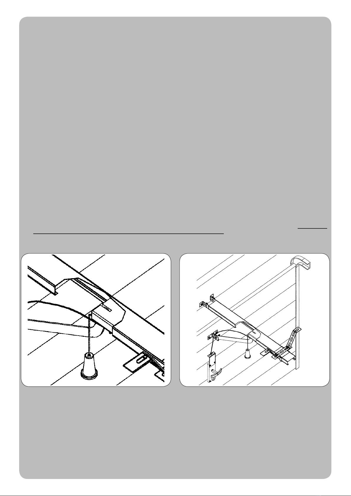
4
Tirer le bouton vers le bas et agir manuellement sur la porte. Tourner la poignée et agir manuellement sur la porte.
La manœuvre manuelle doit être exécutée UNIQUEMENT avec la porte fermée et APRÈS avoir coupé l’alimentation de l’armoire électrique.
Note : si votre installation est munie d’une télécommande qui au bout de quelques temps semble moins bien fonctionner ou ne plus fonctionner du tout,
cela peut dépendre tout simplement de la pile (suivant le type sa durée est de plusieurs mois jusqu’à 2/3 ans). Vous pouvez vous en rendre compte à
travers le fait que le voyant de conrmation de la transmission est faible ou bien, s’il ne s’allume qu’un bref instant. Avant de vous adresser à l’installateur,
essayez d’échanger la pile avec celle d’un autre émetteur qui fonctionne correctement : si la cause de l’anomalie est celle-ci, il sufra de remplacer la
pile par une autre du même type.
Si vous désirez ajouter un nouveau type d’automatisme dans votre habitation, adressez-vous au même installateur et à Tau ; en plus du conseil d’un
spécialiste, vous aurez ainsi la garantie des produits les plus évolués sur le marché, du meilleur fonctionnement et du maximum de compatibilité entre
les automatismes.
Nous vous remercions d’avoir lu ces recommandations et nous espérons que votre nouvelle installation vous donnera toute satisfaction : pour tout type
d’exigence, adressez-vous en toute conance à votre installateur.
Français
INSTRUCTIONS ET RECOMMANDATIONS DESTINÉES À L’UTILISATEUR DE L’AUTOMATISATION
FÉLICITATIONS pour avoir choisi pour votre automatisation un produit Tau !
Tau S.r.l. produit des composants pour l’automatisation de portails, portes, barrières, volets : opérateurs, logiques de commande, radiocommandes,
clignotants, photocellules et accessoires.
Les produits Tau sont réalisés exclusivement avec des matériaux et des usinages de qualité et en tant qu’entreprise, nous sommes à la recherche
constante de solutions innovantes qui simplient de plus en plus l’utilisation de nos appareils, soignés sur tous les plans (technique, esthétique et
ergonomique) : dans la vaste gamme Tau, votre installateur peut choisir le produit qui satisfera au mieux vos exigences.
Tau toutefois ne produit pas votre automatisation qui est, en fait, le résultat d’un travail d’analyse, d’évaluation, de choix des matériaux et de réalisation
de l’installation effectué par votre installateur de conance.
Chaque automatisation, par conséquent, est unique et seul votre installateur peut réaliser une installation suivant vos exigences (dans la mesure où
il est doté de l’expérience et de la qualication professionnelle nécessaire), sûre et able dans le temps et, surtout, effectuée dans les règles de l’art,
c’est-à-dire conforme aux normes en vigueur.
Une installation d’automatisation est d’une grande commodité, en plus de représenter un système de sécurité et, avec un minimum d’attentions, elle est
destinée à durer des années.
Même si l’automatisme en votre possession satisfait le niveau de sécurité requis par les normes, cela n’exclut pas l’existence d’un “risque résiduel”,
c’est-à-dire la possibilité que des situations de danger puissent se vérier, à cause d’une utilisation non raisonnable et/ou erronée. Pour cette raison,
nous donnons quelques conseils sur les comportements à suivre pour éviter tout inconvénient :
- À la première utilisation : demandez à votre installateur de vous expliquer l’origine des risques résiduels et lisez ce manuel d’instructions et
de recommandations pour l’utilisateur qui vous a été remis par l’installateur. Conservez le manuel pour tout problème futur et n’oubliez pas de le
remettre à l’éventuel nouveau propriétaire de l’installation.
- L’installation d’automatisation exécute dèlement vos commandes : une utilisation non raisonnable et/ou impropre peut devenir dangereuse.
Évitez par conséquent d’actionner l’automatisme quand des personnes, des animaux ou des objets se trouvent dans son rayon d’action.
- CE N’EST PAS UN JEU ! Faites en sorte que les enfants ne jouent pas à proximité de l’installation et conservez les télécommandes hors de leur
portée.
- Anomalies: à tout comportement anormal de l’installation, coupez l’alimentation électrique de l’automatisme et effectuez le déblocage manuel
(comme sur la gure). Évitez toute intervention personnelle et contactez votre installateur : une fois débloquée, l’installation fonctionnera
manuellement, comme avant l’automatisation.
- Maintenance : pour durer dans le temps et fonctionner en toute sécurité, comme toute autre machine, l’installation a besoin d’une maintenance
périodique. Établissez avec votre installateur un plan de maintenance. Tau conseille une intervention tous les 6 mois pour un usage domestique
normal qui peut varier suivant l’intensité d’utilisation (toujours tous les 3000 cycles de travail).
N.B. N’importe quel type d’intervention (contrôle, maintenance et/ou réparation) doit être effectué uniquement par du personnel qualié.
- Ne pas modier l’installation ni les paramètres de programmation et de réglage : la responsabilité en incombe à l’installateur.
N.B. l’essai de fonctionnement nal, les maintenances périodiques et les éventuelles réparations doivent être documentées (dans les
espaces prévus à cet effet) par qui les exécute et les documents doivent être conservés par le propriétaire de l’installation (EN CASE DE
NON-PRÉSENTATION DE LA DOCUMENTATION, LA GARANTIE N’EST PLUS VALABLE).
- Démantèlement : à la n de la vie de l’installation, assurez-vous que le démantèlement soit effectué par du personnel qualié et que les matériaux
soient recyclés ou mis au rebut suivant les normes en vigueur au niveau local.

15
SKYBOX Series
195
72
120
395 Y140 225
3420
30
g. 1
g. 2
395
110
215 180
195
97.5 97.5
110
g. 3
g. 4 g. 5
g. 6 g. 7
g. 8 g. 9
min. 40 mm min. 120 mm
- - -- - - - - - - - - - - - - - - - - - - - - - - - - - - - - - - - - - - - - - - - - - - - - - - - - - - - - - - - - - - - - - - - - - - - - - - - - - - - - - - - - - - - - - - - - - - - - -
SKYBOX SERIES Disegni - Drawings - Zeichnen - Projets - Dibujos
3255 mm
55 mm
40 mm
minimum

16
SKYBOX Series
g. 10
g. 11
13 mm
10 mm
2 mm
5 mm Ø8 mm
Ø5 mm
g. 13
g. 12
g. 14 g. 15
A
A
1
2
4
5
1
3
A
A
B
B
SKYBOX SERIES Disegni - Drawings - Zeichnen - Projets - Dibujos
Other tau Garage Door Opener manuals


Popular Garage Door Opener manuals by other brands


Nice
Nice IN100 Instructions and warnings for installation and use

SOMFY
SOMFY Dexxo Pro 800 io manual

Keyautomation
Keyautomation TURBO 30 instruction manual

Chamberlain
Chamberlain 2580 1/2 HP owner's manual

Cardin Elettronica
Cardin Elettronica GL Series instruction manual

APRITECH
APRITECH ANTES 24 GUIDE FOR THE INSTALLER


