12
P2000 Series
GEBRAUCH
Es wird ausdrücklich verboten, die Vorrichtung für andere
Zwecke oder unter Umständen einzusetzen, die von den
genannten abweichen. Normalerweise ermöglicht die installierte
elektronische Steuerzentrale (die eine eingebaute elektrische
Kupplung haben muss) die Wahl folgender Funktionen:
Automatisch : ein Steuerimpuls führt das Öffnen und das
Schließen des Gittertores durch.
Halbautomatisch : ein Steuerimpuls führt das Öffnen oder
das Schließen des Gittertores durch.
Bei Stromausfall kann das Tor nach Betätigung der Vorrichtung
„manuelle Entriegelung” auch von Hand funktionieren. Das
über Pufferbatterie speisbare Modell P2000BENC ist imstande,
mindestens 15 vollständige Zyklen (Öffnung und Schließung)
selbständig auszuführen.
Es wird daran erinnert, dass es sich um eine automatische
Vorrichtung handelt, die mit Strom gespeist wird und daher mit
Vorsicht zu verwenden ist. Im besonderen wird vor folgendem
gewarnt:
• die Vorrichtung nicht mit feuchten Händen und/oder feuchten
oder nackten Füßen berühren;
• die Stromversorgung abschalten, bevor das Steuergehäuse
und/oder der Getriebemotor geöffnet werden;
• nicht am Stromkabel ziehen, um den Stecker zu ziehen;
• den Motor nicht berühren, wenn Sie sich nicht sicher sind, dass
er abgekühlt ist
• das Gittertor nur in Bewegung setzen, wenn es vollständig
sichtbar ist;
• außerhalb des Aktionsbereichs des Tors bleiben, wenn es sich
bewegt: warten, bis keine Bewegung mehr erfolgt;
• Kinder oder Tiere nicht in Tornähe spielen lassen;
• Kinder oder unfähige Personen nicht die Fernsteuerung oder
andere Vorrichtungen für die Betätigung verwenden lassen;
• eine regelmäßige Wartung ausführen;
• im Falle eines Defekts, die Stromversorgung abschalten und
das Tor, nur falls möglich uns sicher, von Hand bewegen. Keine
Eingriffe selbst ausführen, sondern sich an einen autorisierten
Techniker wenden.
WARTUNG
Die Antriebe P2000/P2000BENC erfordern wenig Wartung; ihr
guter Betrieb hängt auch von dem Zustand des Tors ab: aus
diesem Grunde beschreiben wir kurz auch die Tätigkeiten, die
durchzuführen sind, um das Tor immer leistungsfähig zu halten.
ACHTUNG: Achtung: niemand mit Ausnahme des
Wartungsmannes,derein Fachtechnikerseinmuss, istbefugt,
die Automatisierung während der Wartung zu steuern.
Es wird daher empfohlen, die Netzstromversorgung abzuschalten,
wodurch auch die Stromschlaggefahr vermieden wird. Falls die
Versorgung dagegen für bestimmte Überprüfungen eingeschaltet
seinmuss,sosindalleSteuervorrichtungen(wieFernbedienungen,
Druckknopftafeln, usw.) mit Ausnahme der vom Wartungsmann
benutzten Vorrichtung zu deaktivieren.
Gewöhnliche Wartung
Jede der folgenden Arbeiten muss wenn nötig und mindestens
alle 6 Monate für den normalen Hausgebrauch (ungefähr 3000
Arbeitszyclen) und alle 2 Monate für den intensiven Gebrauch z.
B. Wohnblockbetrieb (immer ungefähr 3000Arbeitszyklen).
Tor:
- die Angelzapfen des Tors schmieren und einfetten.
Automatisierungsanlage:
- Den einwandfreien Betrieb der Sicherheitsvorrichtungen
(Photozellen, Sicherheitsleiste, etc.) in Zeiten und auf die
Weisen überprüfen, die von den Herstellern vorgeschrieben
werden;
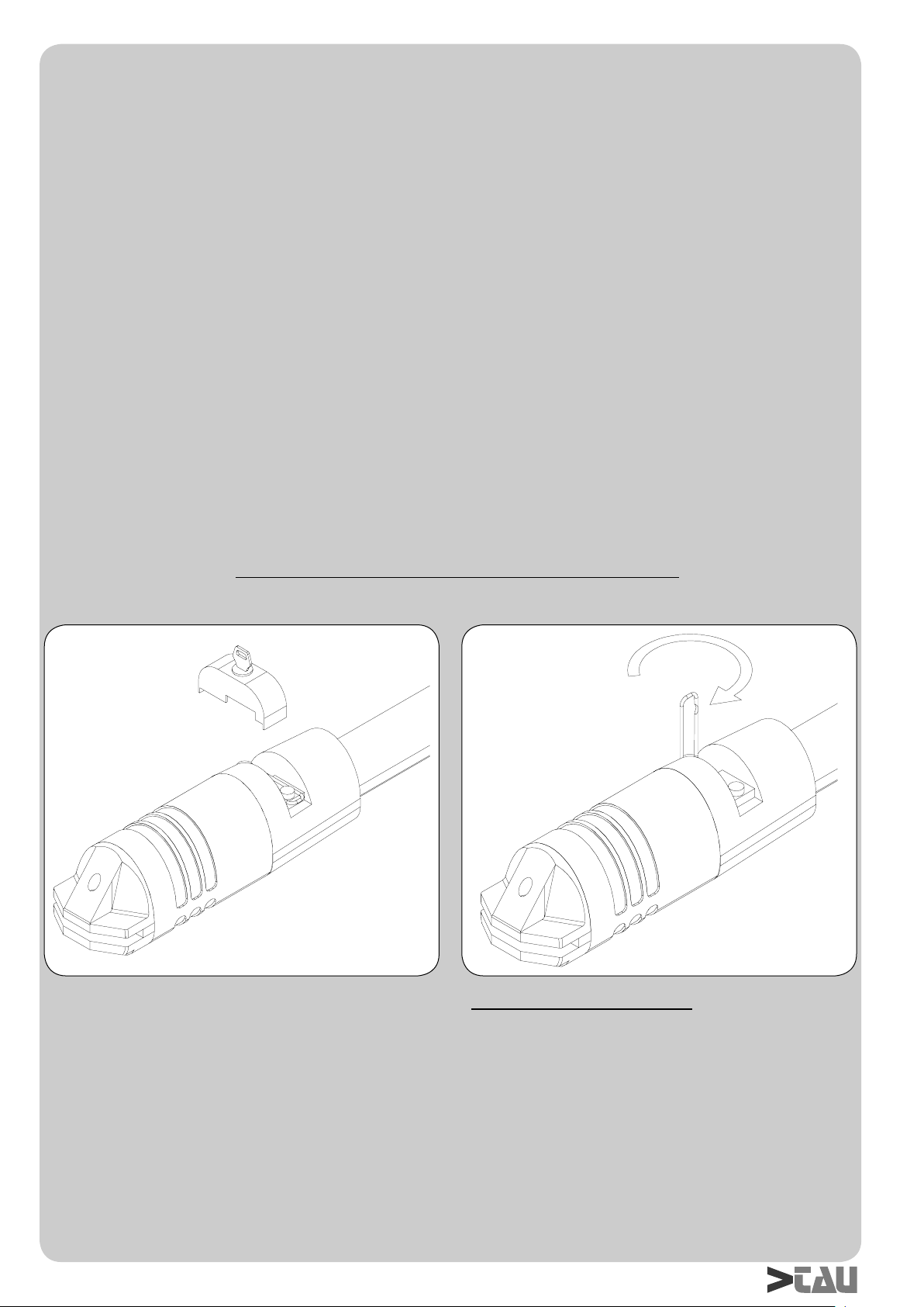
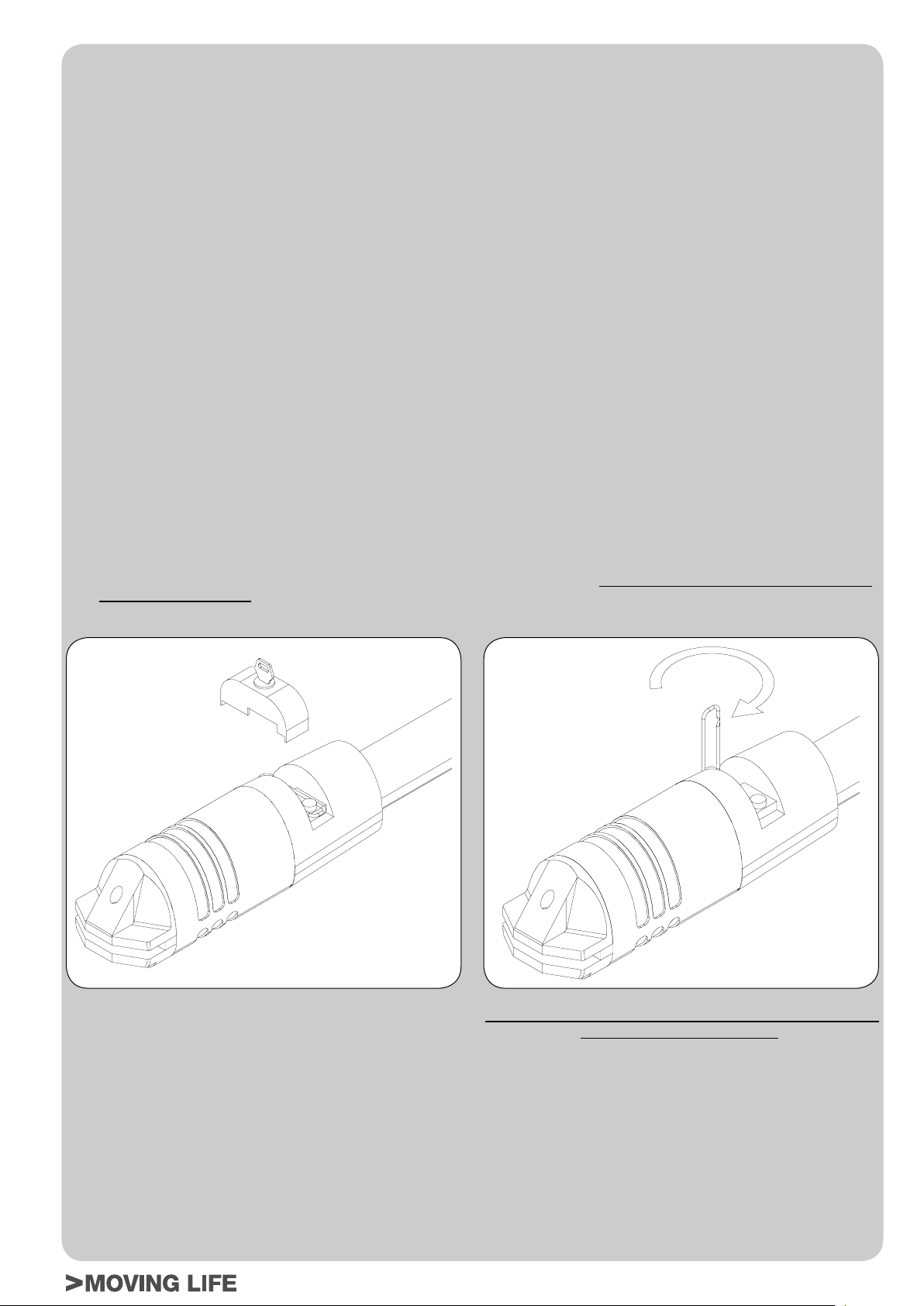
- Die vom unteren Teil des Antriebs aus erreichbare Schnecke
einfetten (mit Fettbüchse, siehe Abb.12); der Gebrauch von
SYNECO Lithiumseifenfett wird empfohlen.
- Den Ladestand der Batterie mit einem Testgerät für Blei-
Säure-Batterien überprüfen; im Falle eines Austausches eine
Originalbatterie verwenden und die leere Einheit gemäß der
gültigen Vorschriften entsorgen (anstelle der Originalbatterie
empfiehlt die Firma TAU den Gebrauch von FIAMM Batterien).
Außergewöhnliche Wartung oder wichtige Störungen
Falls schwierigere Arbeiten an elektromechanischen Teilen
erforderlich sein sollten, wird die Entfernung des defekten Teils
empfohlen, damit eine Reparatur in der Werkstatt durch die
Herstellertechniker oder autorisierte Techniker erfolgen kann.
DEUTSCH
BITTE BEMERKEN: Wir empfehlen, alle Unterlagen der
Anlage in der Steuerzentrale oder in ihrer
unmittelbaren Nähe aufzubewahren.
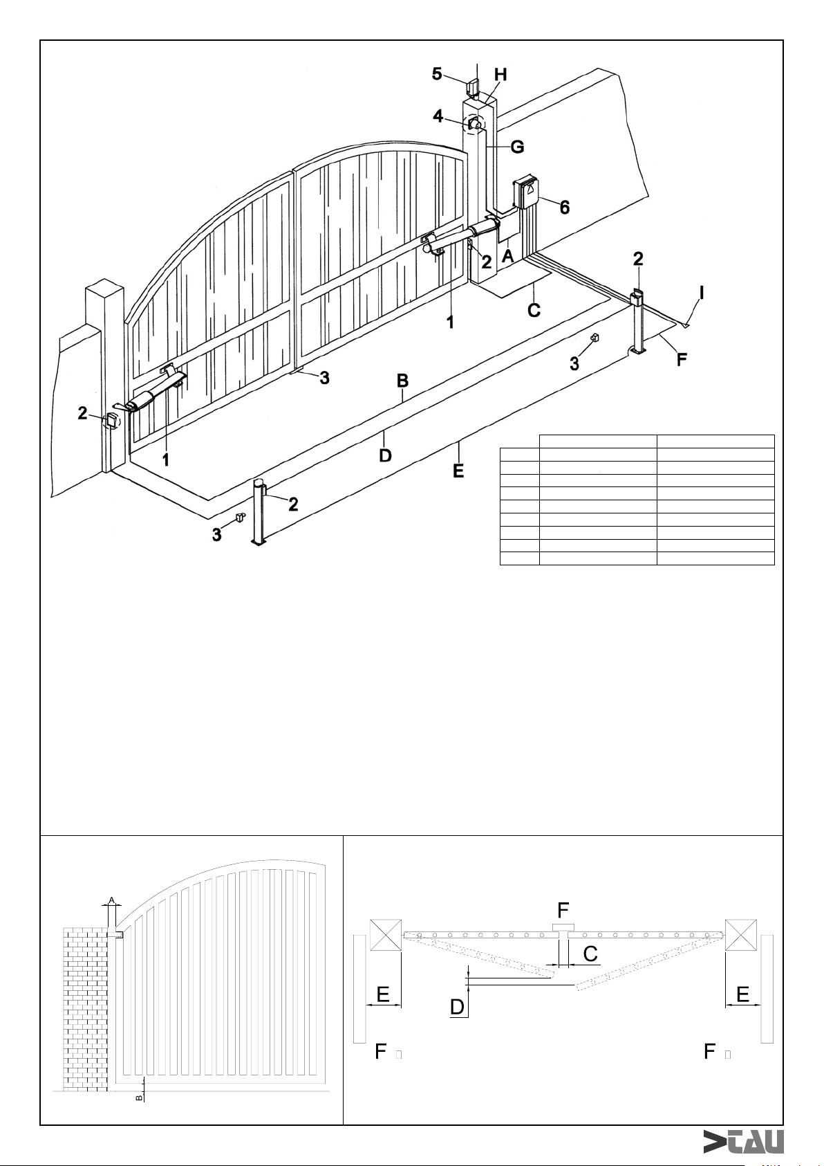
ANLAGE TYP (Abb.13)
NACHTRAG
WELCHE SICHERHEITSFREIRÄUME MUSS ICH EINHALTEN,
WENN ICH EIN TOR AUTOMATISIERE?
• Der Abstand A, Abb.14, zwischen Pfosten und Ständer neben
dem Tor muss während der Tordrehung gleich bleiben. Ändert
sich derAbstand, so muss der Höchstabstand in der gesamten
Höhe ≥25 mm sein, andernfalls muss der so zugänglich
gewordene Raum in der gesamten Torhöhe bis max. 2,5 m
ausgefacht werden.
• Der Abstand B in Abb.14 zwischen Boden und Torflügel
muss ≥50 mm sein; falls der Abstand B aufgrund der
Neigung des Bodens variabel ist, so ist es dem Installateur
überlassen, Maßnahmen zur Reduzierung der Mitnehmgefahr
anzuwenden.
• An einem zweiteiligen Tor muss der Abstand C in Abb.15
zwischen den beiden geschlossenen Torflügeln ≥2,5 cm sein;
dieser Abstand kann mit einer Sicherheitsleiste an der Kante
des einen Torflügels oder einem verformbaren, elastischen
Element im Freiraum zugedeckt werden. Der Abstand kann
auch kleiner oder gleich Null sein, in diesem Fall müssen sich
die Torflügel aber verstellt schließen, so dass ein Raum D von
50 cm, Abb.15 entsteht.
HINWEISE FÜR EINE SICHERE INSTALLATION
Totmannbetrieb:es genügt eine Notstopvorrichtung und eine
Blinkleuchte
Automatischer / halbautomatischer Betrieb: eine Blinkleuchte
muss installiert werden, und der Motordrehmoment muss wie
später beschrieben eingestellt werden; falls diese Einstellung nicht
möglich ist, muss eine Sicherheitsleiste installiert werden.
• zwei Fotozellen anbringen, die eine außerhalb und die andere
innerhalb des Laufwegs, um den Bewegungsbereich des
Tors einzugrenzen. Im Falle einer Überlagerung der Torflügel
mit Anschlagleiste müssen sie verstellt angebracht werden
(Distanz D Abb.15).
Für jede Betriebsweise: Wenn der Torflügel in Öffnung an einem
festen Hindernis (kleine Mauer, Wand, Pfeiler, usw.) mit einem
Abstand (E Abb.15) anhält, der kleiner als 40 cm ist, so muss am
Torflügel oder am festen Teil eine Sicherheitsleiste nach folgenden
Kriterien angebracht werden:
1 - wenn es sich um ein Hindernis handelt, dass sich
vorherrschend in der Höhe (also senkrecht) ausdehnt, so
wird die Sicherheitsleiste (in der ganzen Länge des oben
genannten Hindernisses) in einer Höhe zwischen 40 und 60
cm ab Fußboden angebracht;
2 - wennessichumeinHindernishandelt,dasssichvorherrschend
in der Breite (also waagerecht) ausdehnt und eine Höhe unter
60 cm hat, so wird die Sicherheitsleiste 5 cm ab der oberen
Kante des Hindernisses angebracht.
MERKMALE, EINSTELLUNGEN UND INSTALLATION
DER SICHERHEITSVORRICHTUNGEN
Photozellen :
• Sie werden auf einer Höhe zwischen 40 und 60 cm ab Boden
undineinemHöchstabstandvon10cmabKantedesgeöffneten
Torflügels und ab Rand des geschlossenen Tors angebracht.
Sensible Sicherheitsleiste
• Im einfachsten Fall muss es sich um gewöhnlich geschlossene
NC-Kontakte handeln;
• Die Elastizität bzw. Mindestverformung muss mindestens 1
cm größer sein als der Raum, den das Tor ab Ansprechen der
Vorrichtung zum Stillstand benötigt.
Drehmomentbegrenzer
• Musssoeingestelltwerden,dassderTorflügelbeiVorhandensein
eines mechanischen Widerstands von 150 N (ca. 15 kg), an
seiner Kante gemessen, anhält, wobei die kinetische Energie
des Torflügels nicht größer als 10 J sein darf.