CIRCUIT
BREAKER
TABLE
1-0-3-VOLTAGE
RATING
OF
COMPONENTS
Nominal Voltage
Rating Range
Components (Volts)
Volts
Closing
Re
lay
115 90-130
and
Magnet 450 360-500
Shunt
Trip
115
80-130
450 360-500
1-0-1-2 Auxiliary Switch
The
interrupting
capacities
of the
auxiliary
switch
contacts
are
listed
in
Table
1-0-4.
TABLE
1-0-4-AUXILIARY
SWITCH
Non-Inductive Inductive
Volts
Circuit
Circuit
115
a-c
75
amps.
15.0
amps.
450
a-c
25
amps.
5.0
amps.
Section l-Introduction
1.1·1
GENERAL
This
technical
manual
describes
a Navy
Type ACB 1600HR (Westinghouse
Type
DBN-
1016)
1600-ampere
frame
size
air
circuit
breaker,
meeting
the
requirements
of
Specifica-
tion
MlL-C-17587
for
Naval
Shipboard
service.
Each
circuit
breaker
is
supplied
as
a
complete,
removable
switchboard
assembly
consisting
of
circuit breaker, separable
disconnects
and
as-
sociated
control wiring, drawout
mechanism
and
assemhly
structual
supports
and
back
plate
in·
cluding stationary main bus connections and
sta-
tionary
terminals
for connection
of
the
necessary
external control wiring.
The
complete,
removable
assembly
consists
of two
major
components;
the
stationary
com-
ponent
that
is
bolted
into the
switchboard
frame,
and
the movable component
which
is
the
oper-
ating
mechanism
of the
circuit
breaker
and
may
be
drawn out for inspection, maintenance
or
isolation
from
the
shipboard
electrical
system.
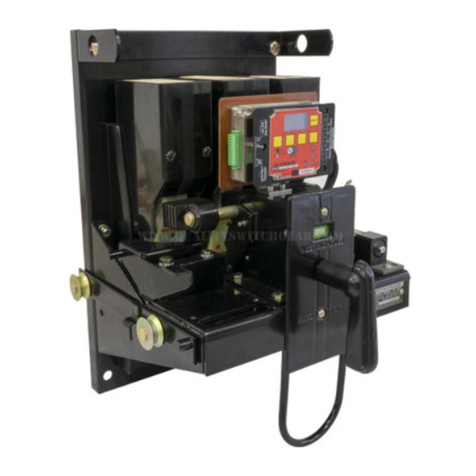
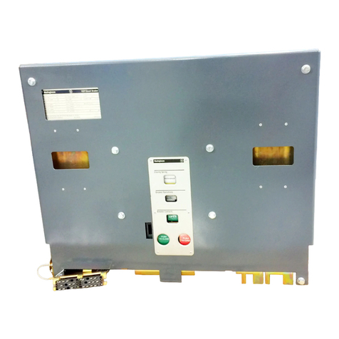
The
general
arrangement
of
this
equipment
is
shown in
figures
1-1-1
and
1-1-2.
The DBN-1016
air
circuit
breaker
is
a
complete,
removable
assembly
for
installation
within a
switchboard
cubicle.
The
circuit
breaker
is
designed
as
an
as-
sembly
including the drawout
mechanism.
These
assemblies
incorporate
disconnect
features
for
both main current connections and secondary
current connections.
This
mounting allows
easy
'·2
removal
and
installation
of the movable
compo-
nent when maintenance operations
are
required.
The
circuit
breaker
is
closed
electrically
from
a
local
or
remote
control
switch.
It
may
be
tripped
from
the
control
switch
or
may
be
tripped
by
depressing
the
"Push-To-Trip"
button
which
protrudes
through
the
face
plate.
For
maintenance, the
emergency
closing
handle
provides
manual
closing
by
inserting
the
operating
handle,
through
the
face
plate,
into
the
socket
provided
in the
operating
mechanism
and
pulling the
operating
handle down
(approxi-
mately
45
degrees)
until
the
breaker
latches.
The moving
component
consists
of a
rigid
steel
chassis
to
which
are
bolted
various
sub-
assemblies.
Each
sub-assembly
is
a
complete
unit
and
is
readily
interchangeable
between
breakers.
In
addition,
each
sub-assembly
may
be
removed
intact
and
easily
replaced
for
mini-
mum outage
time.
·The
sub-assemblies
requiredin
all
breakers
are
the mechanism, pole units,
arc
chutes, aux-
iliary
switch, secondary disconnects,
anti-shock-
closed-device,
anti-shock-open-device,
closing
relay,
and
closing
magnet.
The
remaining
sub-
assemblies
that
may
be
included
are
overcurrent
trip
devices
and shunt
trip
device.
The
air
circuit
breaker
for
three
phase
a-c
service
is
normally provided with overcurrent
trip
devices
in the two
outer
poles,
otherwise
the
three
poles
are
identical.
(
