manuals.online logo
Brands
  1. Home
  2. •
  3. Brands
  4. •
  5. ABB
  6. •
  7. Circuit Breaker
  8. •
  9. ABB SACE Emax 2 User manual

ABB SACE Emax 2 User manual

Other manuals for SACE Emax 2

46

This manual suits for next models

3

Other ABB Circuit Breaker manuals

ABB SACE Emax E2.2 User guide

ABB

ABB SACE Emax E2.2 User guide

ABB ADVAC 03 Installation and operating instructions

ABB

ABB ADVAC 03 Installation and operating instructions

ABB SACE Emax 2 User manual

ABB

ABB SACE Emax 2 User manual

ABB DS 261 User manual

ABB

ABB DS 261 User manual

ABB VD4 36 Quick guide

ABB

ABB VD4 36 Quick guide

ABB H8304 User manual

ABB

ABB H8304 User manual

ABB GE Power Break II User manual

ABB

ABB GE Power Break II User manual

ABB S4 User manual

ABB

ABB S4 User manual

ABB SACE Tmax XT User manual

ABB

ABB SACE Tmax XT User manual

ABB VHK 20 Installation and operating instructions

ABB

ABB VHK 20 Installation and operating instructions

ABB DCBreak Series Programming manual

ABB

ABB DCBreak Series Programming manual

ABB ZX0 User manual

ABB

ABB ZX0 User manual

ABB S800U User manual

ABB

ABB S800U User manual

ABB SACE Emax 2 E2.2 User manual

ABB

ABB SACE Emax 2 E2.2 User manual

ABB SACE Emax E1 User manual

ABB

ABB SACE Emax E1 User manual

ABB RELION 650 SERIES Instructions for use

ABB

ABB RELION 650 SERIES Instructions for use

ABB FSK II S + Operating instructions

ABB

ABB FSK II S + Operating instructions

ABB 5HK Series Installation and operating instructions

ABB

ABB 5HK Series Installation and operating instructions

ABB VM1 Quick guide

ABB

ABB VM1 Quick guide

ABB SACE Emax 2 User manual

ABB

ABB SACE Emax 2 User manual

ABB AC500 V3 User manual

ABB

ABB AC500 V3 User manual

ABB SACE Tmax XT5 User manual

ABB

ABB SACE Tmax XT5 User manual

ABB HD4/R User manual

ABB

ABB HD4/R User manual

ABB VM1 User manual

ABB

ABB VM1 User manual

Popular Circuit Breaker manuals by other brands

Eaton NOVA LBS 15 Installation and operation instructions

Eaton

Eaton NOVA LBS 15 Installation and operation instructions

Gewiss 90 RCD Installation

Gewiss

Gewiss 90 RCD Installation

Siemens SIRIUS 3RV1742 Original operating instructions

Siemens

Siemens SIRIUS 3RV1742 Original operating instructions

WEG FHU ACW125 installation instructions

WEG

WEG FHU ACW125 installation instructions

Siemens Sentron 3VA9157-0PK1 Series operating instructions

Siemens

Siemens Sentron 3VA9157-0PK1 Series operating instructions

hager TS 303 User instruction

hager

hager TS 303 User instruction

ETI EFI-4B Instructions for mounting

ETI

ETI EFI-4B Instructions for mounting

nader NDM3EU-225 operating instructions

nader

nader NDM3EU-225 operating instructions

TERASAKI NHP TemBreak PRO P160 Series installation instructions

TERASAKI

TERASAKI NHP TemBreak PRO P160 Series installation instructions

Gladiator GCB150 Installation instruction

Gladiator

Gladiator GCB150 Installation instruction

Eaton 50DHP-VR Instruction handbook

Eaton

Eaton 50DHP-VR Instruction handbook

OEZ LFN Instructions for use

OEZ

OEZ LFN Instructions for use

Eaton Power Defense PDG2 Instruction leaflet

Eaton

Eaton Power Defense PDG2 Instruction leaflet

Bticino L4412CM2 quick start guide

Bticino

Bticino L4412CM2 quick start guide

Eaton S-T0 Instruction leaflet

Eaton

Eaton S-T0 Instruction leaflet

OEZ 3VA9-RS-4VBH1 Installation, service and maintenance instructions

OEZ

OEZ 3VA9-RS-4VBH1 Installation, service and maintenance instructions

Siemens PSR Instructions, Installation, Operation, Maintenance

Siemens

Siemens PSR Instructions, Installation, Operation, Maintenance

Rockwell Automation Allen-Bradley 140G-G manual

Rockwell Automation

Rockwell Automation Allen-Bradley 140G-G manual

manuals.online logo
manuals.online logoBrands
  • About & Mission
  • Contact us
  • Privacy Policy
  • Terms and Conditions

Copyright 2025 Manuals.Online. All Rights Reserved.

Emax 2
Retrofitting tra interuttori aperti estraibili Emax 2 e AEG ME05
Retrofitting between Emax 2 and AEG ME05 plug-in air circuit-breakers
Nachrüstung zwischen ausfahrbaren offenen Leistungsschaltern Emax 2 und AEG ME05
Reconfiguration entre disjoncteurs ouverts débrochables Emax 2 et AEG ME05
Retrofitting entre interruptores abiertos extraibles Emax 2 y AEG ME05
DOC. N.° 1SDH002116A1001 - ECN000278001 - Rev. B
Attenzione!! Istruzioni riguardanti il solo assemblaggio del kit di retrofitting,
non sono da intendersi come sostitutive del manuale di installazione, uso e
manutenzione dei nuovi interruttori E1.2 E2.2 E4.2.
ori chiarimenti contattare ABB.
Verificare la possibilità di cablare i circuiti ausiliari dei vecchi interuttori
con i nuovi e a confrontarne la compatibilità secondo lo schema elettrico
di equivalenza allegato al kit.1SDM000022A1001
e i vecchi interruttori conservando le viti di
connessione dei poli dei vecchi interruttori AEG ME05 alla barratura
del quadro.
C) Verificare che l’interruttore da sostituire sia installato rispettando le
minime distanze di isolamento verso le pareti, indicate sul manuale
AEG ME05; che tali distanze siano conformi alle dimensioni del
nuovo interruttore, le quali sono riportate nella fig.26 di questo manuale.
C) Make sure that the circuit-breaker to be replaced has been installed
in accordance with the minimum clearances towards the walls indicated
in the AEG ME05 manual and that these clearances conform to the
dimensions of the new circuit-breaker, as given in fig. 26 of this manual.
Warning!! The instructions concern the sole assembly of the retrofitting kit.
They do not substitute the instructions in the installation, operation and
maintenance manual of the new E1.2 E2.2 E4.2 circuit-breaker.
Make sure that the auxiliary circuits of the old circuit-breaker can be wired
to the new one and that the components are compatible, by checking the
equivalent wiring diagram enclosed with the kit.1SDM000022A1001
B) Completely disassemble the old circuit-breaker, but keep the screws
that connect the poles of the old AEG ME05 circuit-breaker to the
switchboard bars.
Il presente kit di retrofitting, è costruito per la sostituzione totale di
interruttori aperti AEG ME05 con interruttori aperti in esecuzione
estraibile di più moderna fattura tipo Emax 2 di medesima taglia,
senza dover eseguire alcuna modifica alle parti attive del quadro.
2. L’interruttore AEG ME05 da sostituire sia installato in conformità
al proprio manuale di installazione, rispettando le distanze di
isolamento verso massa, il dimensionamento delle sbarre di
connessione, il posizionamento del primo setto di ancoraggio.
This retrofitting kit allows AEG ME05 circuit-breakers to be fully
replaced with the more modern Emax 2 plug-in air circuit-breakers
of the same size without having to modify the live parts
of the switchgear in any way.
2. The AEG ME05 circuit-breaker to be replaced has been installed
in compliance with the instructions in the relative installation manual,
and with the specified insulation clearance towards earth, connection
busbar size and position of the first anchor plate.
C) Sicherstellen, dass der auszutauschende
Leistungsschalter unter Beachtung der
Mindestisolationsabstände zu den Wänden
installiert worden ist, die im Handbuch
AEG ME05 angegeben sind;
dass diese Abstände den Abmessungen
des neuen Leistungsschalters entsprechen,
die in der Abb.26 dieses Handbuchs stehen.
Die offenen Leistungsschalter AEG ME05
ganz durch die offenen Leistungsschalter
in der ausfahrbaren Ausführung mit
modernerer Bauart vom Typ Emax 2
2.Dass der zu ersetzende Leistungsschalter
AEG ME05 in Ubereinstimmung mit dem eigenen
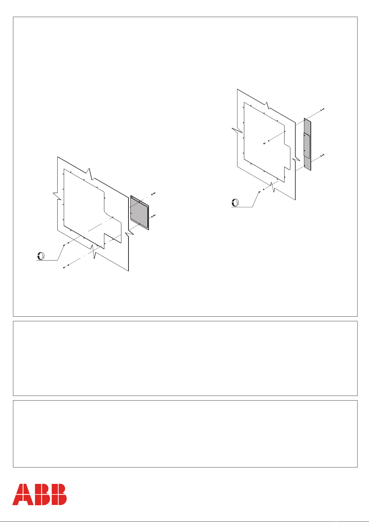
B) Den alten Leistungsschalter ganz ausbaunen
und die Schrauben zum Anschluss der Pole des
alten Leistungsschalter AEG ME05 an der
Sammelschienender Schaltanlage aufbewahren.
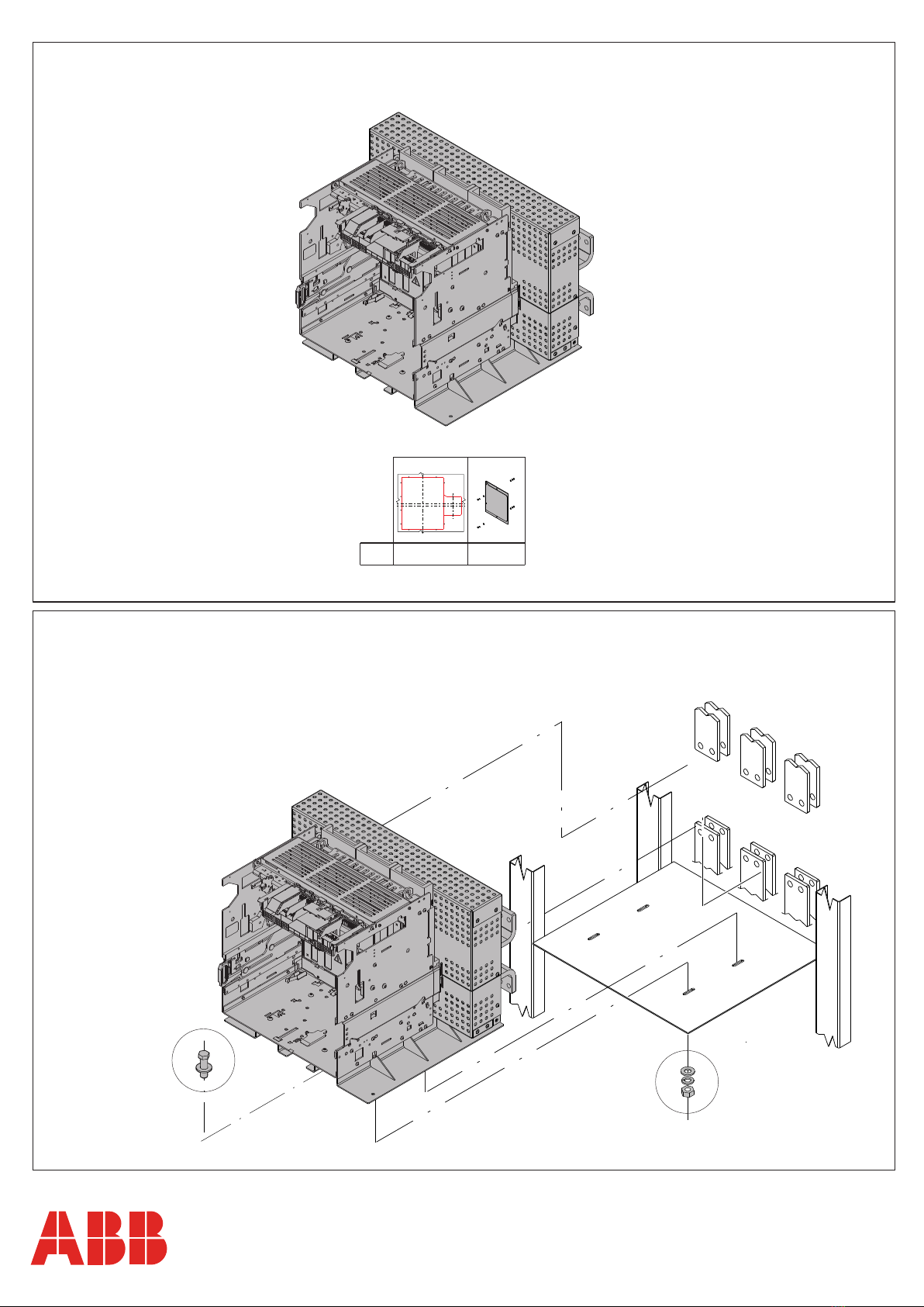
Le prèsent kit de «retrofitting», est conçu puor la
reconfiguration totale de disjoncteurs ouverts
AEG ME05 par des disjoncteurs ouverts dans la
version dèbrochable sur chariot de conception
plus moderne type Emax 2 de même taille,
sans devoir effectuer aucune modification aux
parties actives du tableau.
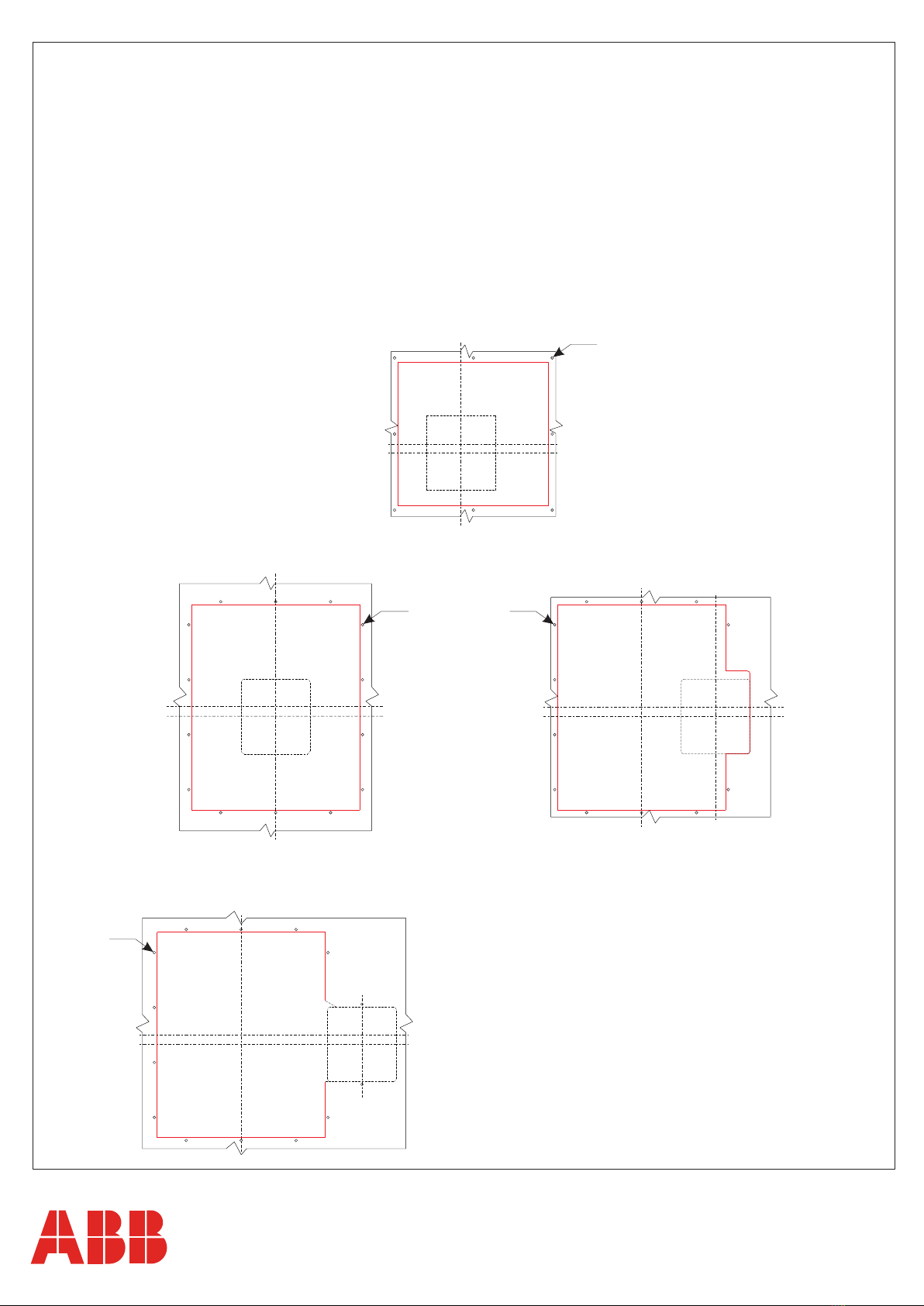
2.Le disjoncter AEG ME05 à remplacer soit
installè conformèment à son manuel d’installation,
en respectant les distances d’isolation vers la
masse, le dimensionnment des barres de
connexion, le positionnement du premier
diaphragme d’ancrage.
E1.2 E2.2 E4.2.
1SDM000022A1001
1SDM000022A1001 1SDM000022A1001
B) Dèmanteler entièrement l’ancien disjoncteur
en conservant les vis de connexion des pôles
de l’ancien disjoncteur AEG ME05 au jeu de
barres du tableau.
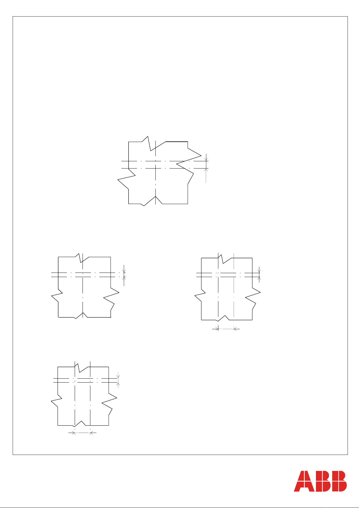
C) Vérifier que le disjoncteur à remplacer soit
installé en respectant les distances minimales
d'isolement envers les parois,
indiquées sur le manuel AEG ME05;
que ces distances sont conformes aux
dimensions du nouveau disjoncteur, qui sont
reportées dans la fig.26 de ce manuel.
B) Desmantelar completamente el viejo interruptor
conservando los tornillos de conexión de los polos
del viejo interruptor AEG ME05 en las barras
del cuadro.
C) Verificar que el interruptor a sustituir esté
instalado respetando las distancias mínimas de
aislamiento hacia las paredes, indicadas en
el manual AEG ME05; que dichas distancias
sean conformes a las dimensiones del nuevo
interruptor, expuestas en la fig.26 de este manual.
El presente kit de retrofitting, ha sido realizado
para la sustitución total de interruptores AEG ME05
con interruptores abiertos en ejecución extraible de
realización más moderna, tipo Emax 2,
del mismo tamaño, sin tener que modificar ninguna
parte activa del cuadro.
2.El interruptor AEG ME05 a sustituir estè
instalado de conformidad con el respectivo
manual de instalación, respetando las distancias
de aislamiento hacia la masa, el dimensionamiento
de las barras de conexión, la colocación del
primer tabique de fijación.
E1.2 E2.2 E4.2 E1.2 E2.2 E4.2.
Tabella di abbinabilità
Compatibility table
Kompatibilitätstabelle
Tableau de compatibilité
Tabla de compatibilidad
(1) = Icw 500 ms
(2) = 3P Only
AEG ME05
nameplate
Iu [A] Emax2 Iu [A]
Iu [A]
(Rating Plug)
Derating
[A]
Icm 690V
[kA]
Icu 690V
[kA]
Icw (690V, 1s)
[kA]
ME 1605 1900 E1.2N 1600 - 1450 105 50
50(1)
ME 2505 2900 E4.2H 3200 - - 180 80 80
ME 3205 3900
E4.2H(2 ) 3200 - 3200 180 80 80
2
1E1.2 / ME 1605
E1.2 / ME 1605
Riusare viteria esistente
Use the existing screws and bolts again
Die vorhandenen Schraubteile wiederbenutzen
Réutiliser la boulonnerie existante
Reutilizar la tornillería existente
1
1
3P
4P
E2.2 / ME 2505
E2.2 / ME 2505
4
3
Riusare viteria esistente
Use the existing screws and bolts again
Die vorhandenen Schraubteile wiederbenutzen
Réutiliser la boulonnerie existante
Reutilizar la tornillería existente
x4
1
1 1
3P
4P
E4.2 / ME 3205
E4.2 / ME 3205
6
5
x4
x4
Riusare viteria esistente
Use the existing screws and bolts again
Die vorhandenen Schraubteile wiederbenutzen
Réutiliser la boulonnerie existante
Reutilizar la tornillería existente
1 1
3P
8
7
Figura esemplificativa, per immagini reali vedere fig.9
Indicative figure. Consult fig.9 for the real images
Als Beispiel gedachte Abbildung, für echte Bilder siehe Abb.9
Figure d'exemple, pour les images réelle voir le fig.9
Figura ejemplificativa, para las imágenes reales véanse la fig.9
- Per una maggiore semplicità dell’operazione di foratura portella quadro si allega al kit una dima adesiva da attaccare secondo la figura seguente.
- To make it easier to make the hole in the switchboard door, the kit comes complete with an adhesive template for attaching as shown in the figure below.
- Zur Erleichterung der Arbeiten zum Realisieren der Bohrungen und des Ausschnitts enthält der Bausatz eine Schablone, die nach der nachstehenden
Abbildung anzubringen ist.
- Pour simplifier encore plus l'opération de perçage de la porte du tableau, on joint au kit un gabarit adhésif à fixer comme sur la figure suivante.
- Para facilitar el taladrado de la tapa, el kit incluye una plantilla adhesiva que se aplica como ilustra la figura siguiente.
DOOR DRILLING USING THE TEMPLATE
Smontare la mostrina del vecchio interruttore.
Disassemble the flange of the old circuit-breaker.
Den Abdeckahmen des alten Leistungsschalters entfernen.
Démonter la garniture de l’ancien disjoncteur.
Desmontar la cubierta de protección del viejo interruptor.
9
3 POLES 4 POLES
Ø5
3 POLES
Ø5
E2.2 / ME2505
E4.2 / ME3205
- Collocare la dima adesiva alla portella e controllare che la linea tratteggiata sia perfettamente corrispondente con li foro già presente sulla portella.
Tagliare la portella seguendo la linea continua rossa e forare secondo i fori rossi.
- Position the adhesive template on the door and make sure that the dotted line perfectly matches the aperture on the door itself.
Cut the door along the continuous red line and make the holes in line with the red hole.
- Die Klebeschablone an der Klappe anbringen und sicherstellen, dass die gestrichelte Linie ganz mit den Loch übereinstimmt, das schon auf der
Klappe vorhanden ist. Den schnitt in der Schaltfeldtür entlang der roten Linie und die Bohrungen bei den roten Kreisen ausführen.
- Placer le gabarit adhésif à la porte et vérifier que la ligne hachurée coïncide parfaitement avec l’ouverture présente sur la porte.
Couper la porte en suivant la ligne continue rouge et percer selon les trousrouges.
- Colocar la plantilla adhesiva en la puerta y controlar que la línea punteada coincida perfectamente con el agujero ya presente en la puerta.
Cortar la tapa a lo largo de la línea continua roja y perforar donde se encuentran los puntos rojos.
DOOR DRILLING USING THE TEMPLATE
Ø5
3-4 POLES
Ø5
E1.2 / ME1605
Y’ Y
Y’ Y
X’ X’
XX
17
138.75
17
Y Y’
Y Y’
XX
X’ X’
3 POLES 4 POLES
10
Y’ Y
Y’ Y
X’ X’
XX
17
220
E4.2 / ME 3205
E2.2 / ME 2505
DOOR DRILLING WITHOUT USING THE TEMPLATE
1SDH000999R0713
1SDH001000R0728
E1.2
E2.2 - E4.2 - E6.2
- Se la linea tratteggiata della dima adesiva non corrisponde con la foratura già presente nella portella,
effettuare il taglio di una nuova portella secondo il posizionamento degli assi. Per le dimensioni di foratura vedere
- If the dotted line of the adhesive template fails to match the aperture in the door, cut a new door according to
the positions of the axes. For the drilling dimensions see
- Wenn die gestrichelte Linie der Klebeschlabone nicht mit der auf der Schaltfeldtür vorhandenen Öffnung den
Schnitt der neuen Schaltfeldtür wie gezeigt gemäß der Lage der Achsen ausführen. Für die Bohrung Abmessungen siehe
- Si la ligne hachurée de le gabarit adhésif ne coïncide pas avec le perçage présent sur la porte, effectuer
la découpe d’une nouvelle porte, suivant le positionnement des axes. Pour les dimensions de perçage voir
- Si la línea puntead de la plantilla adhesiva no coincide con la perforación ya presente en la puerta,
efectuar el corte de una nueva portezuela respetando la posición de los ejes. Para las dimensiones de taladrado véase
3-4 POLES
15,5
X’
X
X’
X
Y Y’
Y Y’
E1.2 / ME 1605
Asse verticale
Vertical axis
Vertikale achse
Axe vertical
Eje vertical
Y =
Asse orizzontale
Horizontal axis
Horizontal achse
Axe horizontal
Eje horizontal
X =
ME05
Asse verticale
Vertical axis
Vertikale achse
Axe vertical
Eje vertical
Y’ =
Asse orizzontale
Horizontal axis
Horizontal achse
Axe horizontal
Eje horizontal
X’ =
EMAX 2
4 POLES
E2.2 / ME 2500
3 POLES
E4.2 / ME 3200
11
1Nm
1Nm
Assemblare adattatore portella sul lato interno
Assemble the door adapter on internal side
Den Türadapter auf der innenseite montieren
Assembler l’adaptateur de porte sur le côté intérieur
Ensamble el adaptador de puerta en el lado interno
13
Cablare i circuiti ausiliari secondo schema elettrico
Wire the auxiliary circuits as shown in wiring diagram
Die Hilfsstromkreise nach dem Schaltplan verdrahten
Câbler les circuits auxiliaires d’après le schéma électrique
Cablear los circuitos auxiliares siguiendo el esquema eléctrico
Montare la protezione IP30 come indicato nel foglio kit
Assemble the IP30 protection as indicated in the kit instructions
Den Schutz IP30 montieren wie angegeben im Bausatzblatt
Monter la protection IP30 comme indiqué dans la fiche du kit
Monte la protección IP30 como se indica en la hoja del kit
12
1SDH000999R0713
1SDH001000R0728
E1.2
E4.2
1SDM000022A1001