Eaton AMH-4.76-VR User manual

March 2016
Instruction Book IB182023EN
AMH-4.76-VR
Replacement Circuit Breaker
Supercedes October 2013
Effective
AMH-4.76-VR 4.76 1200A Shown

ii Instruction Book IB182023EN March 2016 www.eaton.com
AMH-4.76-VR
Replacement Circuit Breaker
WARNING
IMPROPERLY INSTALLING OR MAINTAINING THESE PRODUCTS CAN
RESULT IN DEATH, SERIOUS PERSONAL INJURY OR PROPERTY DAMAGE.
READ AND UNDERSTAND THESE INSTRUCTIONS BEFORE ATTEMPTING
ANY UNPACKING, ASSEMBLY, OPERATION OR MAINTENANCE OF THE
CIRCUIT BREAKERS.
INSTALLATION OR MAINTENANCE SHOULD BE ATTEMPTED ONLY
BY QUALIFIED PERSONNEL. THIS INSTRUCTION BOOK SHOULD NOT
BE CONSIDERED ALL INCLUSIVE REGARDING INSTALLATION OR
MAINTENANCE PROCEDURES. IF FURTHER INFORMATION IS REQUIRED,
YOU SHOULD CONSULT EATON’S ELECTRICAL SERVICES & SYSTEMS.
THE CIRCUIT BREAKERS DESCRIBED IN THIS BOOK ARE DESIGNED AND
TESTED TO OPERATE WITHIN THEIR NAMEPLATE RATINGS. OPERATION
OUTSIDE OF THESE RATINGS MAY CAUSE THE EQUIPMENT TO FAIL,
RESULTING IN DEATH, BODILY INJURY AND PROPERTY DAMAGE.
ALL SAFETY CODES, SAFETY STANDARDS AND/OR REGULATIONS AS
THEY MAY BE APPLIED TO THIS TYPE OF EQUIPMENT MUST BE STRICTLY
ADHERED TO.
THESE VACUUM REPLACEMENT CIRCUIT BREAKERS ARE DESIGNED TO
BE INSTALLED PURSUANT TO THE AMERICAN NATIONAL STANDARDS
INSTITUTE (ANSI). SERIOUS INJURY, INCLUDING DEATH, CAN RESULT
FROM FAILURE TO FOLLOW THE PROCEDURES OUTLINED IN THIS
MANUAL.
DISCLAIMER OF WARRANTIES AND LIMITATION OF LIABILITY
The information, recommendations, descriptions and safety notations in this document are based on Eaton’s experience and judgment and
may not cover all contingencies. If further information is required, an Eaton sales office should be consulted. Sale of the product shown in
this literature is subject to the terms and conditions outlined in appropriate Eaton selling policies or other contractual agreement between
Eaton and the purchaser.
THERE ARE NO UNDERSTANDINGS, AGREEMENTS, WARRANTIES, EXPRESSED OR IMPLIED, INCLUDING WARRANTIES OF FITNESS
FOR A PARTICULAR PURPOSE OR MERCHANTABILITY, OTHER THAN THOSE SPECIFICALLY SET OUT IN ANY EXISTING CONTRACT
BETWEEN THE PARTIES. ANY SUCH CONTRACT STATES THE ENTIRE OBLIGATION OF EATON. THE CONTENTS OF THIS DOCUMENT
SHALL NOT BECOME PART OF OR MODIFY ANY CONTRACT BETWEEN THE PARTIES.
In no event will Eaton be responsible to the purchaser or user in contract, in tort (including negligence), strict liability or other-wise for any
special, indirect, incidental or consequential damage or loss whatsoever, including but not limited to damage or loss of use of equipment,
plant or power system, cost of capital, loss of power, additional expenses in the use of existing power facilities, or claims against the
purchaser or user by its customers resulting from the use of the information, recommendations and descriptions contained herein. The
information contained in this manual is subject to change without notice.
This product was manufactured by Eaton at the Power Breaker
Center (PBC): 310 Maxwell Avenue, Greenwood, SC 29646.
All possible contingencies which may arise during installation,
operation or maintenance, and all details and variations of this
equipment do not purport to be covered by these instructions. If
further information is desired by purchaser regarding his particular
installation, operation or maintenance of particular equipment,
contact an Eaton representative.

iii
Instruction Book IB182023EN March 2016 www.eaton.com
AMH-4.76-VR
Replacement Circuit Breaker
Table of Contents
SECTION 1: INTRODUCTION 4
1.1 VISUAL INSTRUCTION BOOKLET ESSENTIALS 4
1.2 QUICK RESPONSE CODE 4
1.3 AVAILABLE AMH-4.76-VR CIRCUIT BREAKERS 4
SECTION 2: SAFE PRACTICES 6
SECTION 3: RECEIVING, HANDLING, AND STORAGE 7
3.1 RECEIVING 7
3.2 HANDLING 7
3.3 STORAGE 8
3.4 AMH-4.76-VR APPROXIMATE WEIGHTS 8
SECTION 4: DESCRIPTION AND OPERATION 11
4.1 VACUUM INTERRUPTER 11
4.1.1 THE INTERRUPTER ASSEMBLY 11
4.1.2 CONTACT EROSION INDICATOR 11
4.1.3 CONTACT WIPE AND STROKE 12
4.2 PHASE BARRIERS 12
4.3 BUSHINGS AND DISCONNECTING
CONTACT ASSEMBLIES 12
4.4 STORED ENERGY MECHANISM 12
4.4.1 CLOSING SPRING CHARGING 12
4.4.2 CLOSING OPERATION 13
4.4.3 TRIPPING OPERATION 13
4.4.4 TRIP-FREE OPERATION 13
4.5 CONTROL SCHEMES 13
4.5.1 TIMING 13
4.6 SECONDARY CONNECTION BLOCK 13
4.7 INTERLOCKS 13
4.7.1 ANTI-CLOSE INTERLOCK 13
4.7.2 RACKING SYSTEM TRIP AND
SPRING RELEASE INTERLOCKS 13
4.8 MISCELLANEOUS ITEMS 15
4.8.1 MOC OPERATOR 15
4.8.2 OPERATIONS COUNTER 15
SECTION 5: INSPECTION & INSTALLATION 19
5.1 EXAMINATION FOR DAMAGE 19
5.1.1 NAMEPLATE VERIFICATION 19
5.2 SURE CLOSE MECHANISM ADJUSTMENT 19
5.3 MANUAL OPERATION CHECK 20
5.4 VACUUM INTERRUPTER INTEGRITY 20
5.5 LOW FREQUENCY WITHSTAND
TEST (INSULATION CHECK) 20
5.6 CONTACT EROSION AND WIPE 20
5.7 PRIMARY CIRCUIT RESISTANCE 20
5.8 ELECTRICAL OPERATIONS CHECK 20
5.9 DESCRIPTION OF OPERATIONAL POSITIONS 21
5.10 INSERTION PROCEDURE 21
5.11 REMOVAL PROCEDURE 22
SECTION 6: INSPECTION & MAINTENANCE 23
6.1 INSPECTION FREQUENCY 23
6.2 INSPECTION AND MAINTENANCE PROCEDURES 23
6.3 VACUUM INTERRUPTER INTEGRITY TEST 24
6.4 CONTACT EROSION AND WIPE 24
6.5 INSULATION 25
6.6 INSULATION INTEGRITY CHECK 25
6.7 PRIMARY CIRCUIT RESISTANCE CHECK 26
6.8 MECHANISM CHECK 26
6.8.1 CLOSURE™ TEST 26
6.9 LUBRICATION 29
SECTION 7: REPLACEMENT PARTS 31
7.1 GENERAL 31
7.2 ORDERING INSTRUCTIONS 31

4Instruction Book IB182023EN March 2016 www.eaton.com
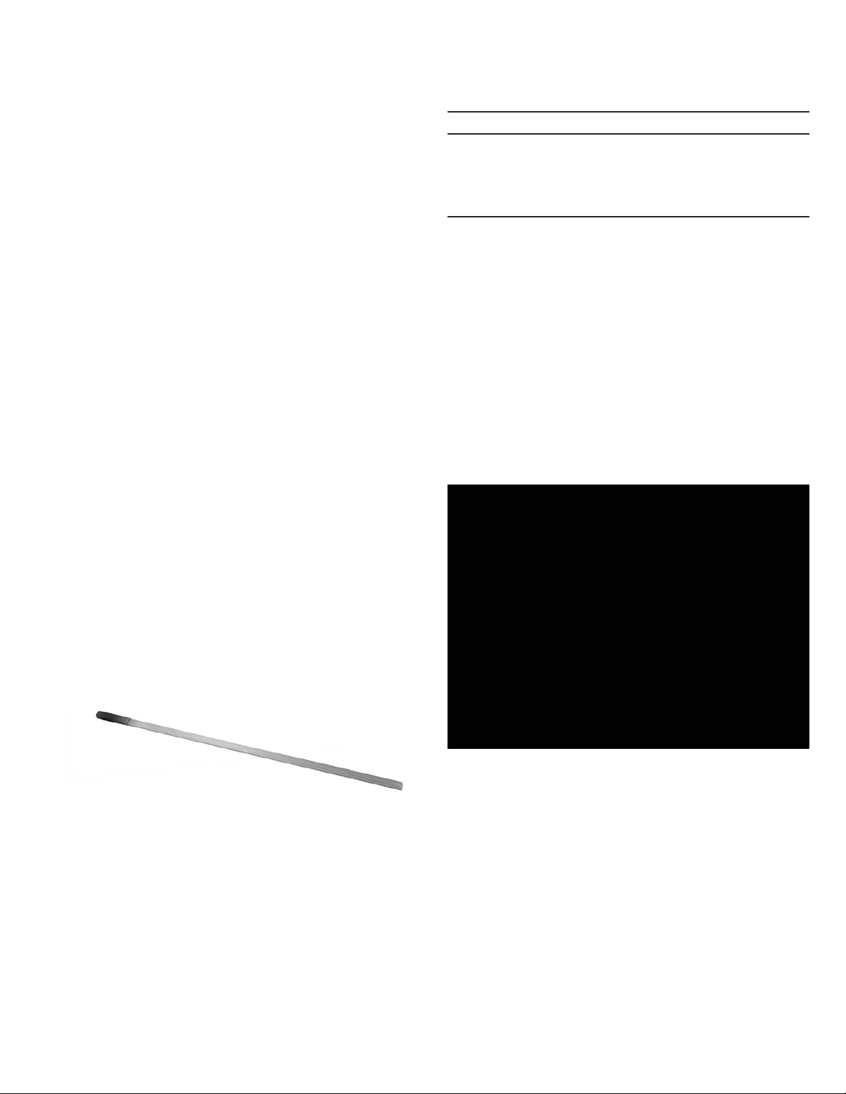
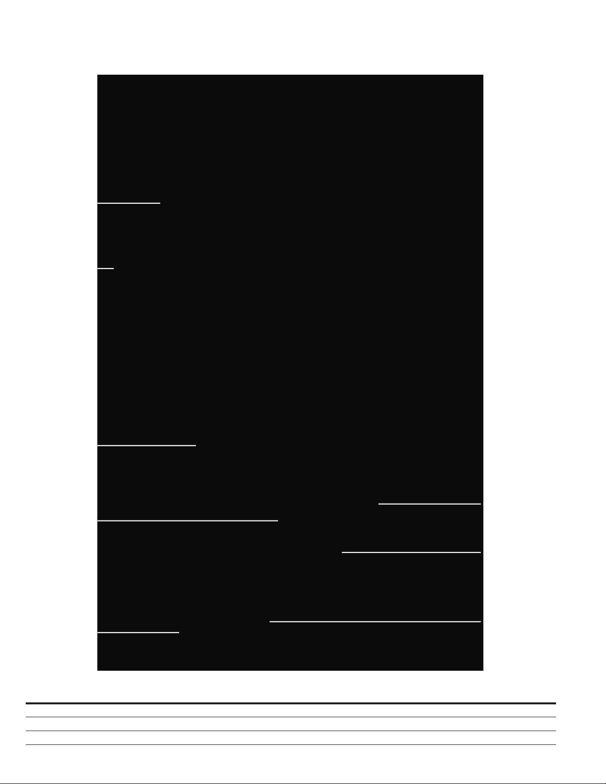
AMH-4.76-VR
Replacement Circuit Breaker
SECTION 1: INTRODUCTION
The purpose of this book is to provide instructions for receiving
and handling, storage, installation, operation and maintenance of
the General Electric type AMH-4.76 VR-Series circuit breaker. The
Vacuum Replacement Circuit Breakers (also referred to as VR-Series)
are designed to be used in existing AMH-4.76 metal-clad switchgear
and provide equal or superior electrical and mechanical performance
as compared to the design ratings of the original circuit breaker.
VR-Series Circuit Breakers provide reliable control, protection and
performance, with ease of handling and maintenance. Like ratings
are interchangeable with each other.
This book is intended to be used in conjunction with the technical
information provided with the original equipment order which
includes, but is not limited to electrical control schematics and wiring
diagrams, outline diagrams, installation plans, and procedures for
installation and maintenance of accessory items.
Satisfactory performance is dependant upon proper application,
correct installation, and adequate maintenance. It is strongly
recommended that this instruction book be carefully read and
followed in order to realize optimum performance and long useful life
of the circuit breaker.
1.1 VISUAL INSTRUCTION BOOKLET ESSENTIALS
Eaton provides additional documentation designed to enhance the
technical information provided in this instruction booklet for the
VR-Series circuit breakers. The Visual Instruction Booklet Essentials
(VIBE) is a digital supplemental booklet featuring user interactive
content and informative videos intended to assist with the
maintenance of the VR-Series circuit breaker. The VIBE document is
available for immediate download at www.eaton.com/VR-Series.
1.2 QUICK RESPONSE CODE
VR-Series circuit breakers have a quick response code (QR Code) on
the escutcheon of the circuit breaker cover. This QR Code is a matrix
barcode that provides direct access to download VR-Series specific
documentation, such as product instruction booklets and the VIBE
documentation. See Figure 1.1 for the featured VR-Series QR Code.
ote:N A smart phone with an adequate QR Code Scanner application must be
used. Downloading content may incur data charges from the mobile service
provider.
WARNING
SATISFACTORY PERFORMANCE OF THESE BREAKERS IS CONTINGENT
UPON PROPER APPLICATION, CORRECT INSTALLATION AND ADEQUATE
MAINTENANCE. THIS INSTRUCTION BOOK MUST BE CAREFULLY READ
AND FOLLOWED IN ORDER TO OBTAIN OPTIMUM PERFORMANCE
FOR LONG USEFUL LIFE OF THE CIRCUIT BREAKERS. IT IS FURTHER
RECOMMENDED THAT THE INSTALLATION BE PERFORMED BY A EATON
CORPORATION TRAINED ENGINEER OR TECHNICIAN.
VR-SERIES BREAKERS ARE PROTECTIVE DEVICES, AS SUCH, THEY ARE
MAXIMUM RATED DEVICES. THEREFORE, THEY SHOULD NOT UNDER ANY
CIRCUMSTANCE BE APPLIED OUTSIDE THEIR NAMEPLATE RATINGS.
ALL POSSIBLE CONTINGENCIES WHICH MIGHT ARISE DURING
INSTALLATION, OPERATION, OR MAINTENANCE, AND ALL DETAILS
AND VARIATIONS OF THIS EQUIPMENT ARE NOT COVERED BY THESE
INSTRUCTIONS. IF FURTHER INFORMATION IS DESIRED BY THE
PURCHASER REGARDING A PARTICULAR INSTALLATION, OPERATION, OR
MAINTENANCE OF THIS EQUIPMENT, THE LOCAL EATON REPRESENTATIVE
SHOULD BE CONTACTED.
1.3 AVAILABLE AMH-4.76-VR CIRCUIT BREAKERS
Refer to Table 1.
Table 1. AMH-4.76-VR Availability and Interchangeability
Breaker
Type
Nominal
Voltage
Class
(kV)
Existing
Breaker
MVA
Rating
Existing Breaker
Rated Continuous
Current at 60 Hz
(Amps)
MVA
Designation
of VR-Series
Breaker
Rated
Voltage
Factor
K
Rated Withstand ANSI Test Voltage Rated Short-Circuit
kA RMS at Rated
Max kV
Closing and Latching /
Momentary Capabilities
kA RMS/Peak
Low Freq.
kV RMS
Impulse
kV Crest
AMH-4.76-VR 4.16 250 1200 / 2000 250 1.24 19 60 29 58 / 97
4.16 250 1200 / 2000 250U 1.19 19 60 41 78 / 132
Figure 1.1. Quick Response Code
VR-Series QR Code

5
Instruction Book IB182023EN March 2016 www.eaton.com
AMH-4.76-VR
Replacement Circuit Breaker
E
H
I
G
F
J
H
DB
C C
A
Table 2. AMH-4.76-VR Dimensions
Breaker Type
Existing Breaker
Rated Continuous
Current at 60 Hz
(Amps) A B C D E F G H I J
AMH-4.76-VR 250/250U 1200 / 2000 56.02 23.44 7.00 44.42 40.07 7.50 18.38 26.50 8.50 42.00

6Instruction Book IB182023EN March 2016 www.eaton.com
AMH-4.76-VR
Replacement Circuit Breaker
SECTION 2: SAFE PRACTICES
VR-Series breakers are equipped with high speed, high energy
operating mechanisms. They are designed with several built-in
interlocks and safety features to provide safe and proper operating
sequences.
WARNING
TO PROTECT THE PERSONNEL ASSOCIATED WITH INSTALLATION,
OPERATION, AND MAINTENANCE OF THESE BREAKERS, THE FOLLOWING
PRACTICES MUST BE FOLLOWED:
• Only qualified persons, as defined in the National Electrical
Safety Code, who are familiar with the installation and
maintenance of medium voltage circuits and equipment,
should be permitted to work on these breakers.
• Read these instructions carefully before attempting any
installation, operation or maintenance of these breakers.
• Always remove the breaker from the enclosure before
performing any maintenance. Failure to do so could result
in electrical shock leading to death, severe personnel injury
and/or property damage.
• Do not work on a breaker with the secondary test coupler
engaged. Failure to disconnect the test coupler could result
in an electrical shock leading to death, personnel injury and/
or property damage.
• Do not work on a closed breaker or a breaker with closing
springs charged. The closing spring should be discharged
and the main contacts open before working on the breaker.
Failure to do so could result in cutting or crushing injuries.
• Do not use a circuit breaker by itself as the sole means of
isolating a high voltage circuit. Remove the breaker to the
Disconnect position and follow all lockout and tagging rules
of the National Electrical Code and any and all applicable
codes, regulations and work rules.
• Do not leave the breaker in an intermediate position in the
cell. Always have the breaker either in the Test or Connected
position. Failure to do so could result in a flash over and
possible death, personnel injury or property damage.
• Always remove the maintenance tool from the breaker after
charging the closing springs.
• Breakers are equipped with safety interlocks. Do not defeat
them. This may result in death, bodily injury or equipment
damage.

7
Instruction Book IB182023EN March 2016 www.eaton.com
AMH-4.76-VR
Replacement Circuit Breaker
SECTION 3: RECEIVING, HANDLING, AND
STORAGE
Type AMH-4.76 VR-series circuit breakers are subjected to complete
factory production tests and inspection before being packed. They
are shipped in packages designed to provide maximum protection to
the equipment during shipment and storage and at the same time to
provide convenient handling. Accessories such as the maintenance
tool, cell code plate, (if applicable) etc. are shipped with the breaker
(Figure 3.1).
3.1 RECEIVING
Until the breaker is ready to be delivered to the switchgear site
for installation, DO NOT remove it from the shipping crate. If the
breaker is to be placed in storage, maximum protection can be
obtained by keeping it in its crate.
Upon receipt of the equipment, inspect the crates for any signs of
damage or rough handling. Open the crates carefully to avoid any
damage to the contents. Use a nail puller rather than a crow bar
when required.
When opening the crates, be careful that any loose items or
hardware are not discarded with the packing material. Check the
contents of each package against the packing list.
Examine the breaker for any signs of shipping damage such as
broken, missing or loose hardware, damaged or deformed insulation
and other components. File claims immediately with the carrier if
damaged or loss is detected and notify the nearest Eaton’s Electrical
Services & Systems office.
Tools and Accessories
Maintenance Tool / Manual Charge Handle: This tool is used
to manually charge the closing spring. One maintenance tool is
provided with each vacuum unit replacement breaker. (Style#
94C9506G01)
Racking Handle: The racking handle is used to drive the racking
mechanism which moves the circuit breaker into and out of the cell.
The original OEM racking handle will interface with the VR-Series
replacement breaker racking mechanism and is therefore not
provided as part of the vacuum replacement breaker. A replacement
racking handle may be purchased directly from Eaton. (Style#
5D11330G01)
3.2 HANDLING
WARNING
DO NOT USE ANY LIFTING DEVICE AS A PLATFORM FOR PERFORMING
MAINTENANCE, REPAIR OR ADJUSTMENT OF THE BREAKER OR FOR
OPENING, CLOSING THE CONTACTS OR CHARGING THE SPRINGS. THE
BREAKER MAY SLIP OR FALL CAUSING SEVERE PERSONAL INJURY.
ALWAYS PERFORM MAINTENANCE, REPAIR AND ADJUSTMENTS ON A
WORKBENCH CAPABLE OF SUPPORTING THE BREAKER TYPE.
VR-Series breaker shipping containers are designed to be handled
either by use of an overhead lifting device or by a fork lift truck. If
containers must be skidded for any distance, it is preferable to use
roller conveyors or individual pipe rollers.
Once a breaker has been inspected for shipping damage, it is best
to return it to its original shipping crate until it is ready to be installed
in the Metal-Clad Switchgear.
When the breaker is ready for installation, a lifting harness in
conjunction with an overhead lift or portable floor lift can be used
to move the breaker. If the breaker is to be lifted, position the lifting
device over the breaker and insert the lifting harness hooks into the
breaker side lifting points and secure (lifting straps should have at
least a 500lbs lift capacity over the approximate breaker weight). Be
sure the hooks are firmly attached before lifting the breaker. Stand a
safe distance away from the breaker while lifting and moving.
Figure 3.1.a. Typical Manual Charge Handle
Figure 3.1.b. Rotary Racking Handle
Figure 3.2. Lifting AMH-4.76-VR

8Instruction Book IB182023EN March 2016 www.eaton.com
AMH-4.76-VR
Replacement Circuit Breaker
3.3 STORAGE
If the circuit breaker is to be placed in storage, maximum protection
can be obtained by keeping it in the original shipping crate. Before
placing it in storage, checks should be made to make sure that the
breaker is free from shipping damage and is in satisfactory operating
condition.
The breaker is shipped with its contacts open and closing springs
discharged. The indicators on the front panel should confirm this.
Insert the maintenance tool in the manual charge socket opening
(Figure 3.3, 3.5, & 3.7). Charge the closing springs by pumping the
handle up and down about 36 times until a crisp metallic “click”
is heard. This indicates that the closing springs are charged and is
shown by the closing spring “charged” (yellow) indicator. Remove
the maintenance tool. Push the “manual close” button. The breaker
will close as shown by the breaker contacts “closed” (red) indicator.
Push the “manual trip” button. The breaker will trip as shown by the
breaker contacts “open” (green) indicator. After completing this initial
check, leave the closing springs “discharged” and breaker contacts
“open”.
Outdoor storage is NOT recommended. If unavoidable, the outdoor
location must be well drained and a temporary shelter from sun,
rain, snow, corrosive fumes, dust, dirt, falling objects, excessive
moisture, etc. must be provided. Containers should be arranged
to permit free circulation of air on all sides and temporary heaters
should be used to minimize condensation. Moisture can cause
rusting of metal parts and deterioration of high voltage insulation.
A heat level of approximately 400 watts for each 100 cubic feet of
volume is recommended with the heaters distributed uniformly
throughout the structure near the floor.
Indoor storage should be in a building with sufficient heat and
circulation to prevent condensation. If the building is not heated, the
same general rule for heat as for outdoor storage should be applied.
3.4 AMH-4.76-VR APPROXIMATE WEIGHTS
Refer to Table 3.
Table 3. Maximum Weight by Type
Type Amperes LBs
AMH-4.76-VR 250 1200 535
2000 785
AMH-4.76-VR 250U 1200 535
2000 785

9
Instruction Book IB182023EN March 2016 www.eaton.com
AMH-4.76-VR
Replacement Circuit Breaker
Figure 3.3. Front External View of AMH-4.76-VR
Front External View
1Manual Charging Socket 5Guide Bar 9MOC Actuator
2Push To Close Button 6Breaker Contacts Indicator 10 Push To Open Button
3Racking Access Door 7Springs Charge/Discharge 11 Position Indicator
4Foot Pedal 8Operations Counter
1
2
3
4
5
9
10
11
8
7
6

10 Instruction Book IB182023EN March 2016 www.eaton.com
AMH-4.76-VR
Replacement Circuit Breaker
Figure 3.4. Rear External View of AMH-4.76-VR
Rear External View
1Shutter Actuator 4SURE CLOSE Spring 7Secondary Disconnect
2Primary Disconnect 5Guide Rail 8Ground Contact
3Racking Screw 6Racking Access Door Interlock
1
2
3
4
5
6
7
8

11
Instruction Book IB182023EN March 2016 www.eaton.com
AMH-4.76-VR
Replacement Circuit Breaker
SECTION 4: DESCRIPTION AND
OPERATION
VR-Series vacuum replacement breakers are designed to be used
with existing installations of equivalent air-magnetic metal-clad
switchgear breakers. The front mounted spring type stored energy
mechanism facilitates inspection and provides improved access
to components for servicing. The long life characteristics of the
vacuum interrupters and proven high reliability of spring-type stored
energy mechanisms assure long, trouble-free service with minimum
maintenance.
VR-Series element designation is easily identified by the mechanism
chassis width. See Table below.
VR-SERIES
ELEMENT DESIGNATION
APPROXIMATE MECHANISM
CHASSIS WIDTH (INCH)
18WR
20WR
29WR
18
20
27
4.1 VACUUM INTERRUPTER
Vacuum interrupters offer the advantages of enclosed arc
interruption, small size and weight, longer life, reduced maintenance,
minimal mechanical shock, and elimination of contact degradation
caused by environmental contamination.
In the closed position, current flows through the interrupter moving
and fixed stems and the faces of the main contacts. As the contacts
part, an arc is drawn between the contact surfaces. The arc is rapidly
moved away from the main contacts to the slotted contact surfaces
by self-induced magnetic effects. This minimizes contact erosion and
hot spots on the contact surfaces. The arc flows in an ionized metal
vapor and as the vapor leaves the contact area, it condenses into the
metal shield which surrounds the contacts.
At current zero, the arc extinguishes and vapor production ceases.
Very rapid dispersion, cooling, recombination, and deionization of the
metal vapor plasma and fast condensation of metal vapor causes the
vacuum to be quickly restored and prevents the transient recovery
voltage from causing a restrike across the gap of the open contacts.
4.1.1 THE INTERRUPTER ASSEMBLY
Each interrupter is assembled at the factory as a unit to assure
correct dimensional relationships between working components.
The interrupter assembly consists of a vacuum interrupter, a
molded glass polyester stand-off insulator, upper and lower clamps,
flexible shunts, bell crank, operating rod, and contact load spring.
The vacuum interrupter is mounted vertically with the fixed stem
upward and the moving stem downward. The upper and lower glass
polyester stand-off insulator and clamps support the interrupter
and are fastened to the breaker’s stored energy mechanism frame.
Upper and lower flexible shunts provide electrical connections from
each interrupter to the breaker’s primary bushings while providing
isolation from mechanical shock and movement of the interrupter’s
moving stem. The operating rod, loading spring, and bell crank
transfer mechanical motion from the breaker’s operating mechanism
to the moving stem of the interrupter. A vacuum interrupter contact
erosion indicator is located on the moving stem of the interrupter. It
is visible when the breaker is withdrawn and is viewed from the rear
of the breaker. (See Figure 6.1 and Figure 6.2)
4.1.2 CONTACT EROSION INDICATOR
The purpose of the contact erosion indicator is to monitor the
erosion of the vacuum interrupter contacts, which is very minimal
over time with Eaton vacuum interrupters utilizing copper-chrome
contact material. A contact erosion indicator mark is located on the
moving stem of the interrupter (Figure 6.1 and 6.2).
In order to determine if the contacts have eroded to the extent that
the interrupter must be replaced, close the breaker and observe
the erosion mark placed on each moving stem from the rear of the
Figure 4.1. 18WR Interrupter Assembly
Figure 4.2. 18WR Interrupter Assembly (All Three Pole Units)

12 Instruction Book IB182023EN March 2016 www.eaton.com
AMH-4.76-VR
Replacement Circuit Breaker
breaker. If the mark on the interrupter stem is visible, the interrupter
is satisfactory. If the mark is no longer visible, the interrupter
assembly must be replaced.
The erosion indicator is easily viewed from the rear on the 5kV, 7.5kV
or 15kV designs.
WARNING
FAILURE TO REPLACE THE INTERRUPTER ASSEMBLY WHEN INDICATED BY
THE CONTACT EROSION INDICATOR COULD CAUSE THE BREAKER TO FAIL,
LEADING TO DEATH, PERSONAL INJURY OR PROPERTY DAMAGE.
4.1.3 CONTACT WIPE AND STROKE
Contact wipe is the indication of the force holding the vacuum
interrupter contacts closed and the energy available to hammer the
contacts open with sufficient speed for interruption.
Stroke is the gap between fixed and moving contacts of a vacuum
interrupter with the breaker open.
The circuit breaker mechanism provides a fixed amount of motion
to the operating rods. The first portion of the motion is used to
close the contacts (i.e. stroke) and the remainder is used to further
compress the preloaded wipe spring. This additional compression
is called wipe. Wipe and stroke are thus related to each other.
As the stroke increases due to the erosion of contacts, the wipe
decreases. A great deal of effort and ingenuity has been spent in the
design of VR-Series breakers, in order to eliminate any need for field
adjustment of wipe or stroke.
WARNING
THERE IS NO PROVISION FOR IN-SERVICE ADJUSTMENTS OF CONTACT
WIPE AND STROKE. ALL SUCH ADJUSTMENTS ARE FACTORY SET AND
SHOULD NOT BE ATTEMPTED IN THE FIELD.
4.2 PHASE BARRIERS
Phase barriers are sheets of insulation located between the
interrupter pole assemblies and on the sides of the breaker frame.
The phase barriers are designed to isolate energized conductor
components in each phase from the adjacent phase and ground.
WARNING
ALL PHASE BARRIERS MUST BE IN PLACE BEFORE PLACING THE
CIRCUIT BREAKER INTO SERVICE. FAILURE TO HAVE THEM IN POSITION
CAN CAUSE DEATH, SERIOUS PERSONNEL INJURY AND/OR PROPERTY
DAMAGE.
4.3 BUSHINGS AND DISCONNECTING CONTACT
ASSEMBLIES
The line and load bushing assemblies, which are the primary
circuit terminals of the circuit breaker, consist of six silver plated
conductors. Solid stab type primary disconnecting contacts at
the ends of the conductors provide means for connecting and
disconnecting the breaker to the bus terminals in the switchgear
compartment.
4.4 STORED ENERGY MECHANISM
The spring-type stored energy operating mechanism is mounted on
the breaker frame and in the front of the breaker. Manual closing
and opening controls are at the front panel (Figure 3.3). They are
accessible while the breaker is in any of its four basic positions. (See
Section 5 in this manual)
The mechanism stores the closing energy by charging the closing
springs. When released, the stored energy closes the breaker,
charges the wipe and resets the opening springs. The mechanism
may rest in any one of the four positions shown in Figure 4.6 as
follows:
a. Breaker open, closing springs discharged.
b. Breaker open, closing springs charged.
c. Breaker closed, closing springs discharged.
d. Breaker closed, closing springs charged.
The mechanism is a mechanically “trip-free” design. Trip-free is
defined later in this section.
In normal operation the closing spring is charged by the spring
charging motor, and the breaker is closed electrically by the
switchgear control circuit signal to energize the spring release coil.
Tripping is caused by energizing the trip coil through the control
circuit.
For maintenance inspection purposes the closing springs can be
charged manually by using the maintenance tool and the breaker can
be closed and tripped by pushing the “Push to Close” and “Push to
Open” buttons on the front panel.
WARNING
KEEP HANDS AND FINGERS AWAY FROM BREAKER’S INTERNAL PARTS
WHILE THE BREAKER CONTACTS ARE CLOSED OR THE CLOSING SPRINGS
ARE CHARGED. THE BREAKER CONTACTS MAY OPEN OR THE CLOSING
SPRINGS DISCHARGE CAUSING CRUSHING INJURY. DISCHARGE
THE SPRINGS AND OPEN THE BREAKER BEFORE PERFORMING ANY
MAINTENANCE, INSPECTION OR REPAIR ON THE BREAKER.
THE DESIGN OF THIS CIRCUIT BREAKER ALLOWS MECHANICAL CLOSING
AND TRIPPING OF THE BREAKER WHILE IT IS IN THE “CONNECT”
POSITION. HOWEVER, THE BREAKER SHOULD BE CLOSED MECHANICALLY
ONLY IF THERE IS POSITIVE VERIFICATION THAT LOAD SIDE CONDITIONS
PERMIT. IT IS RECOMMENDED THAT CLOSING THE BREAKER IN THE
“CONNECT” POSITION ALWAYS BE DONE WITH THE CUBICLE DOOR
CLOSED. FAILURE TO FOLLOW THESE DIRECTIONS MAY CAUSE DEATH,
PERSONAL INJURY, OR PROPERTY DAMAGE.
ELECTRICAL TRIPPING CAN BE VERIFIED WHEN THE BREAKER IS IN THE
“TEST” POSITION.
4.4.1 CLOSING SPRING CHARGING
Figure 4.5 shows schematic section views of the spring charging
parts of the stored energy mechanism.
The major component of the mechanism is a cam shaft assembly
which consists of a shaft to which are attached two closing spring
cranks (one on each end), the closing cam, drive plate, and a free-
wheeling ratchet wheel.
The ratchet wheel (6) is actuated by an oscillating ratchet lever
(12) and drive pawl (10) driven by the motor eccentric cam. As the
ratchet wheel rotates, it pushes the drive plates which in turn rotate
the closing spring cranks and the closing cam on the cam shaft.
The motor will continue to run until the limit switch “LS” contact
disconnects the motor.
The closing spring cranks have spring ends connected to them,
which are in turn coupled to the closing springs. As the cranks
rotate, the closing springs get charged.
The closing springs are completely charged, when the spring cranks
go over dead center and the closing stop roller (9) comes against the
spring release latch (1). The closing springs are now held in the fully
charged position.
The closing springs may also be charged manually as follows: Insert
the maintenance tool in the manual charging socket. Move it up and
down several times (about 36) until a clicking sound is heard and
closing spring status indicator shows “charged” (Figure 3.3). Any
further motion of the maintenance tool will result in free wheeling of
the ratchet wheel and will not result into advance of charging.

13
Instruction Book IB182023EN March 2016 www.eaton.com
AMH-4.76-VR
Replacement Circuit Breaker
4.4.2 CLOSING OPERATION
Figure 4.6 shows the positions of the closing cam and tripping
linkage for four different operational states. In Figure 4.6.a the
breaker is open and the closing springs are discharged. In this state,
the trip latch is disengaged from the trip “D” shaft (unlatched). After
the closing springs become charged, the trip latch snaps into the
fully reset or latched position (Figure 4.6.b)
When the spring release clapper (Figure 4.5, Item 13) moves into
the face of the spring release coil (electrically or manually), the upper
portion of the clapper pushes the spring release latch (1) upward.
When the spring release latch moves, the cam shaft assembly is
free to rotate. The force of the closing cam (Figure 4.6.b, Item 5),
moving the main link (2), rotating the pole shaft (4) (which charges
the opening spring). This moves the three operating rods (3), closes
the main contacts and charges the contact loading springs (not
shown). The operational state immediately after the main contacts
close but before the spring charging motor recharges the closing
springs is illustrated in Figure 4.6.c. Interference of the trip “D” shaft
with the trip latch prevents the linkage from collapsing, and holds
the breaker closed.
Figure 4.6.d shows the breaker in the closed state after the closing
springs have been recharged. The recharging of the spring rotates
the closing cam one half turn. In this position the main link roller
rides on the cylindrical portion of the cam, and the main link does
not move out of position.
4.4.3 TRIPPING OPERATION
When the trip bar “D” shaft (Figure 4.6.b, Item 9) is turned by
movement of the shunt trip clapper (11), the trip latch will slip past
the straight cut portion of the trip bar shaft and will allow the banana
link and main link roller to rise. The energy of the opening spring and
contact loading springs is released to open the main contacts. The
mechanism is in the state illustrated (Figure 4.6.b) after the breaker
is tripped open.
4.4.4 TRIP-FREE OPERATION
When the manual trip button is held depressed, any attempt to close
the breaker results in the closing springs discharging without any
movement of the pole shaft or vacuum interrupter stem.
4.5 CONTROL SCHEMES
There are two basic control schemes for each series of Type VCP-WR
breakers, one for DC control and one for AC control voltages (Figure
4.3). Specific wiring schematics and diagrams are included with each
breaker.
There may be different control voltages or more than one tripping
element, but the principal mode of operation is as follows:
As soon as the control power is applied, the spring charging motor
automatically starts charging the closing spring. When the springs
are charged, the motor cut off LS1/bb switch turns the motor off. The
breaker may be closed by making the control switch close (CS/C)
contact. Automatically upon closing of the breaker, the motor starts
charging the closing springs. The breaker may be tripped any time by
making the control switch (CS/T) contacts.
Note the position switch (PS1) contact in the spring release circuit
in the scheme. This contact remains made while the breaker is
being racked between the TEST and CONNECTED positions for
appropriately retrofitted breakers. Consequently, it prevents the
breaker from closing automatically, even though the control close
contact may have been made while the breaker is racked to the
CONNECTED position.
When the CS/C contact is made, the SR closes the breaker. If
the CS/C contact is maintained after the breaker closes, the Y relay
is picked up. The Y/a contact seals in Y until CS/C is opened. The
Y/b contact opens the SR circuit, so that even though the breaker
would subsequently open, it could not be reclosed before CS/C was
released and remade. This is the anti-pump function.
4.5.1 TIMING
The opening and closing times for the circuit breakers vary
depending upon the control voltage, power rating, environment and
test equipment. Differences in timing are expected between initial
factory measurements and field inspections. Circuit breaker timing
can be measured by service personnel using available equipment
before installation and in conjunction with regular maintenance
periods to assist in tracking the general health of the breaker. Typical
ranges as observed using nominal control voltages are listed in
Table 4.
Table 4. Time Per Event
Event Milliseconds / Maximum
Closing Time
(From Initiation of Close Signal to Contact Make)
75
Opening Time
(Initiation of Trip Signal to Contact Break)
45
Reclosing Time
(Initiation of Trip Signal to Contact Make)
190
4.6 SECONDARY CONNECTION BLOCK
The breaker control circuit is connected to the switchgear control
through secondary connection block, located at the lower left
rear of the breaker. The contacts engage automatically when the
breaker is racked into the “test” and “connect” positions. The
socket half of the connection is located in the cubicle and a jumper
of multiconductor cable can complete the control connections (for
testing) when the breaker is withdrawn from the cell.
4.7 INTERLOCKS
WARNING
INTERLOCKS ARE PROTECTIVE DEVICES FOR PERSONNEL AND
EQUIPMENT. DO NOT BYPASS, MODIFY, OR MAKE INOPERATIVE ANY
INTERLOCKS. DOING SO COULD CAUSE DEATH, SERIOUS PERSONAL
INJURY, AND/OR PROPERTY DAMAGE.
There are several interlocks built into the VR-Series vacuum
replacement breakers. Each of these interlocks, though different in
form, duplicate or exceed in function that of the original breaker.
These interlocks exist to safeguard personnel and equipment. The
basic premise behind the interlocking arrangement on the vacuum
replacement breaker is that the breaker must not be inserted into
or removed from a live circuit while the main contacts are closed.
Also considered in the interlocking is that the breaker should pose
no greater risk than necessary to the operator in or out of the cell.
In addition to the original interlocks, VR-Series breakers provide an
anti-close interlock.
4.7.1 ANTI-CLOSE INTERLOCK
The anti-close interlock prevents discharging of the closing springs if
the breaker is already closed (Figure 4.5, Item 11). When the breaker
is closed, the interlock component moves away from the spring
release clapper so that it cannot lift the spring release latch (9).
4.7.2 RACKING SYSTEM TRIP AND SPRING RELEASE
INTERLOCKS
The racking interlock prevents engaging or disconnecting a shut
breaker with live cell buss work or removing a mechanically
hazardous breaker from the cell. The basic premise of this interlock
is that no breaker should be connected to or removed from cell
primary circuitry when shut and no breaker should be removed
from the cell with charged open or closing springs. The racking

14 Instruction Book IB182023EN March 2016 www.eaton.com
AMH-4.76-VR
Replacement Circuit Breaker
Figure 4.3. Typical AC/DC Schematic
Closed until springs are fully charged
Open until springs are fully charged
Closed until springs are fully charged
Open until mechanism is reset
Open in all except between ‘Test’
and’Connect’ positions
Closed in all except between ‘Test’
and ‘Connect’ positions
OPERATION
‘C’ and ‘NO’
‘C’ and ‘NC’
‘C’ and ‘NO’
‘C’ and ‘NO’
‘C’ and ‘NC’
‘C’ and ‘NO’
Brown Switch
Black Switch
Black Switch
Brown Switch
SWITCH TERMINAL
LS1
bb
LS2
aa
LS2
bb
LC
PS1
PS2
Breaker Control Switch - close
Breaker Control Switch - trip
Anti Pump Relay
Spring Release Coil (Close Coil)
Spring Charging Motor
Shunt Trip Coil
Protective Relay
Terminal Block or Accessible Terminal
Position Switch 1
Position Switch 2
-
-
-
-
-
-
-
-
-
-
CS
C
CS
T
Y
SR
M
ST
PR
O
PS1
PS2
VR-Series Circuit Breaker dc Control Schematic
VR-Series Circuit Breaker ac Control Schematic

15
Instruction Book IB182023EN March 2016 www.eaton.com
AMH-4.76-VR
Replacement Circuit Breaker
interlock accomplishes this by providing a trip signal to the breaker
automatically from the racking mechanism interlock cams whenever
the breaker is in an intermediate position in the cell and adding a
close signal between the DISCONNECT and WITHDRAWN positions
to render the breaker trip-free prior to leaving the cell (close and
open springs discharged).
WARNING
DO NOT FORCE THE BREAKER INTO THE CELL. DOING SO MAY DAMAGE
PARTS THEREBY RISKING DEATH, PERSONAL INJURY, AND/OR PROPERTY
DAMAGE.
4.8 MISCELLANEOUS ITEMS
4.8.1 MOC OPERATOR
The MOC switch is external to the circuit breaker and mounted
within the confines of the switchgear cubicle. The breaker’s MOC
operator interfaces with the cell MOC switch in the same manner as
the original breaker being replaced. All VR-Series breakers, which are
supplied with MOC operators, are engineered with patented SURE
CLOSE Technology. This technology decouples the MOC operator
from the main breaker operating mechanism. This prevents the MOC
switch from stalling the circuit breaker during a closing operation,
preventing damage to the cell MOC components, and extends the
life of the MOC switch.
WARNING
EXTREME CARE SHOULD BE TAKEN TO AVOID PERSONNEL OR EQUIPMENT
CONTACT WITH THE MOC SYSTEM WHEN OPERATING THE BREAKER DUE
TO THE ASSOCIATED MECHANICAL FORCE. CONTACT WITH THE MOC
OPERATOR DURING OPERATION COULD RESULT IN INJURY.
4.8.2 OPERATIONS COUNTER
All AMH-4.76-VR breakers are equipped with a mechanical
operations counter (Figures 3.3). As the breaker opens, the linkage
connected to the pole shaft lever advances the counter reading by
one.

16 Instruction Book IB182023EN March 2016 www.eaton.com
AMH-4.76-VR
Replacement Circuit Breaker
Figure 4.4. 18WR Vacuum Element - Front Faceplate Removed
18WR Vacuum Element
1LH Closing Spring 5Spring Release Assembly 9Manual Charge Socket
2Motor Cutoff Switch 6Shunt Trip Assembly 10 Ratchet wheel
3Latch Check Switch (Rear) 7RH Closing Spring 11 Operations Counter
4Closing Cam 8Reset / Opening Spring 12 Charging Motor
1
2
3
5
6
4
7
8
9
10
11
12

17
Instruction Book IB182023EN March 2016 www.eaton.com
AMH-4.76-VR
Replacement Circuit Breaker
Figure 4.5. Closing Cam and Trip Linkage
Breaker Open, Springs Discharged Breaker Closed, Springs Charged
Closing Cam and Trip Linkage
1Spring Release (Close) Latch 6Ratchet Wheel 11 Anti-Close Interlock
2Pole Shaft 7Spring Crank 12 Motor Ratchet Lever
3Closing Spring Fixed End 8Cam Shaft 13 Spring Release (Close) Clapper
4Closing Spring 9Spring Release Latch (Close Roller) 14 Spring Release (Close) Coil
5Holding Pawl (Electrical Charging) /
Drive Pawl (Manual Charging)
10 Drive Pawl (Electrical Charging) /
Holding Pawl (Manual Charging)
2
1
3
4
5
6
7
8
9
10
11
12
13
14

18 Instruction Book IB182023EN March 2016 www.eaton.com
AMH-4.76-VR
Replacement Circuit Breaker
Figure 4.6. Charging Schematic
4
1
2
3
5
6
7
8
9
10
11
12
4.9.a. Breaker Open and Closing Spring Discharged
4.9.c. Breaker Closed and Closing Spring Discharged
4.9.b. Breaker Open and Closing Spring Charged
4.9.d. Breaker Closed and Closing Spring Charged
Charging Schematic
1Main Link Roller 5Closing Cam 9Trip Bar “D” Shaft
2Main Link 6Cam Shaft 10 Trip Latch Reset Spring
3Operating Rod 7Banana Link 11 Shunt Trip Lever
4Pole Shaft 8Trip latch 12 Shunt Trip Coil

19
Instruction Book IB182023EN March 2016 www.eaton.com
AMH-4.76-VR
Replacement Circuit Breaker
SECTION 5: INSPECTION & INSTALLATION
WARNING
BEFORE PLACING THE BREAKER IN SERVICE, CAREFULLY FOLLOW THE
INSTALLATION PROCEDURE BELOW AND THE SAFE PRACTICES SET
FORTH IN SECTION 2. NOT FOLLOWING THE PROCEDURE MAY RESULT IN
INCORRECT BREAKER OPERATION LEADING TO DEATH, BODILY INJURY,
AND PROPERTY DAMAGE.
When the breaker is first commissioned into service and each time
the breaker is returned to service, it should be carefully examined
and checked to make sure it is operating correctly.
5.1 EXAMINATION FOR DAMAGE
Examine the breaker for loose or obviously damaged parts. Never
attempt to install nor operate a damaged breaker.
5.1.1 NAMEPLATE VERIFICATION
Verify the information on the new VR-Series nameplate matches
the information on the purchase order. If any discrepancies exist,
notify Eaton’s Electrical Services & Systems for resolution prior to
proceeding.
WARNING
ALWAYS DE-ENERGIZE/ISOLATE THE POWER SOURCE FEEDING THE
POWER CIRCUIT BREAKERS/SWITCHGEAR AND LOCK-OUT/TAG-OUT THE
POWER SOURCE PRIOR TO INSERTION OR REMOVAL OF ANY POWER
CIRCUIT BREAKER. NEVER ATTEMPT TO MAINTAIN OR MODIFY A CIRCUIT
BREAKER WHILE INSERTED IN A SWITCHGEAR CELL STRUCTURE. ALWAYS
REMOVE THE POWER CIRCUIT BREAKER AND MOVE IT TO A SUITABLE
AREA FOR MAINTENANCE OR REPAIR.
FOLLOW ALL LOCKOUT AND TAG-OUT REQUIREMENTS OF THE NATIONAL
ELECTRIC CODE, OSHA AND ANY OTHER APPLICABLE LOCAL CODES,
REGULATIONS AND PROCEDURES.
5.2 SURE CLOSE MECHANISM ADJUSTMENT
WARNING
FOR ALL TYPE BREAKER HOUSINGS EQUIPPED WITH MECHANISM
OPERATED CELL (MOC) SWITCHES, THE STEPS OUTLINED IN THIS
SECTION MUST BE PERFORMED BEFORE INSTALLING A REPLACEMENT
VR-SERIES CIRCUIT BREAKER. FAILURE TO COMPLY COULD CAUSE SEVERE
PERSONAL INJURY, DEATH, EQUIPMENT DAMAGE AND/OR IMPROPER
OPERATION
All type AMH-4.76-VR breakers utilize the AMH-4.76-VR SURE
CLOSE mechanism to control kinetic energy transfer and closely
mimic the dynamics and velocities of older breakers. It is imperative
that this mechanism be adjusted to compensate for the force of the
MOC switch mounted in the cell.
The breaker has been factory adjusted to operate one mechanism
operated cell (MOC) switch in the cell. This means that for
applications with either no MOC switch or one MOC switch, no field
adjustments are required.
Finally, the SURE CLOSE mechanism provides an effective way to
evaluate the condition of the MOC in the cell. If the SURE CLOSE
drive spring is properly adjusted, but the MOC does not fully open
or close, it is time to maintain the MOC in the cell. Maintenance
usually means cleaning and lubricating the MOC mechanism.
If the MOC has seen a large number of cycles, however, worn
components may have to be replaced.
To insure the proper operation of the SURE CLOSE mechanism, the
MOC assembly should be cleaned and inspected for worn parts and
then lubricated. A spring force gauge should be used to measure the
forces needed to move the switch to the fully closed position prior
to inserting the breaker. The differential force of the assembly and
the breaker should be a minimum of 10 lbs. with the breaker having
the higher recorded force. Should the forces be less than that,
proceed with the following steps to increase the breaker force:
WARNING
MEASUREMENTS AND ADJUSTMENTS SHOULD NEVER BE ATTEMPTED
IN AN ENERGIZED STRUCTURE. IF THE STRUCTURE CAN NOT BE
DE-ENERGIZED, THEN PROPER PERSONAL PROTECTIVE EQUIPMENT
PER NFPA 70E MUST BE WORN AT ALL TIMES WHILE GATHERING MOC
SWITCH DATA, ADJUSTING OR SERVICING THE MOC SWITCH. FAILURE TO
COMPLY WITH THIS WARNING COULD CAUSE SEVERE PERSONAL INJURY,
DEATH, EQUIPMENT DAMAGE AND/OR IMPROPER OPERATION.
To adjust the SURE CLOSE drive spring for a specific number of
MOC switches, proceed with the following steps:
Step 1: Locate the MOC drive spring (Figure 3.3). It is located in the
left lower portion of the breaker as viewed from the rear of the
breaker.
Step 2: From the factory, the drive spring comes set with adequate
force to operate one MOC switch, however, more force can be
generated. Refer to Figure 5.1 to see how that adjustment would
look. Notice that there is a nut and a jam nut on the threaded rod
to make the adjustment easy.
Step 3: Using a spring gauge, measure the force required to
operate the MOC to the fully closed position in the cell at the
interface with the breaker.
Step 4: With the breaker out of the cell, close the breaker and
measure the output of the MOC drive with a spring gauge. Open
the breaker. The MOC drive force should exceed the MOC cell
force required by 10 - 15lbs. If not, an adjustment is required.
Step 5: Loosen the jam nut on the SURE CLOSE spring and
compress the spring an additional .25 inches. Close the breaker.
WARNING
WITH THE BREAKER IN THE OPEN POSITION, THE SPRING COMPRESSION
SHOULD NEVER BE SET TO A DIMENSION LESS THAN 3 INCHES AS
MEASURED IN FIGURE 5.1.
Step 6: Remeasure the MOC output spring force in the closed
position. Repeat until the MOC forces are adequate.
Step 7: Insert into the cell.
Step 8: Operate the breaker to verify the new setting.
Step 9: Repeat steps 3 - 7 until acceptable operation is achieved.
Step 10: Anytime an adjustment is made, make sure the new
compressed spring length (measured in the open position) is
recorded if different than the dimension in this instruction book.
Figure 5.1. SURE CLOSE Spring Compression Setting

20 Instruction Book IB182023EN March 2016 www.eaton.com
AMH-4.76-VR
Replacement Circuit Breaker
WARNING
KEEP HANDS OFF THE TOP EDGE OF THE FRONT BARRIER WHEN PUSHING
A BREAKER INTO A CELL. FAILURE TO DO SO COULD RESULT IN BODILY
INJURY, IF FINGERS BECOME WEDGED BETWEEN THE BREAKER AND
THE CELL. USE THE HANDLES PROVIDED ON THE FRONT OF THE BREAKER
FACEPLATE, OR USE BOTH FULLY OPENED HANDS FLAT ON THE FRONT OF
THE FACEPLATE.
These checks can be performed with the breaker in its withdrawn
or disconnect position and connecting the breaker to a test cabinet
or to the switchgear cell’s secondary receptacle using the special
extension cable designed for this purpose and described in Section
3.
Perform electrical operations checks. Close and trip the circuit
breaker electrically several times to verify that the operation is
reliable and consistent. Check that the operation of the spring
charging motor is reasonably prompt and that the motor makes no
unusual noise.
WARNING
DO NOT PERFORM ELECTRICAL OPERATION CHECKS WITH THE BREAKER
IN THE “CONNECT” POSITION BECAUSE OF THE POSSIBILITY OF
CONNECTING DE-ENERGIZED LOAD CIRCUITS TO THE ELECTRICAL POWER
SOURCE, RESULTING IN DEATH, PERSONNEL INJURY OR EQUIPMENT
Step 11: After an adjustment is made, make sure that all nuts are
secured in place, prior to returning to service.
5.3 MANUAL OPERATION CHECK
Manual operational checks must be performed before the breaker
is connected to an energized circuit. Tests must be performed with
the breaker withdrawn from the cell or in the disconnect position.
While the breaker is withdrawn or in the disconnect position, place
the maintenance tool into the manual charge socket opening and
charge the closing springs with about 36 up and down strokes of
the handle. When charging is complete, the closing crank goes over
center with an audible “click” and the springs Charged / Discharged
Indicator shows “Charged”. Remove the maintenance tool.
NOTICE
IF THE SPRINGS ARE TO BE CHARGED ON A CLOSED BREAKER, NO
CLICK IS HEARD AT THE END OF CHARGING OPERATION. DISCONTINUE
CHARGING AND REMOVE THE MAINTENANCE TOOL AS SOON AS
“CHARGED” FLAG IS FULLY VISIBLE. CONTINUE ATTEMPTS TO FURTHER
CHARGE MAY RESULT IN DAMAGE TO THE MECHANISM.
WARNING
ALWAYS REMOVE THE MAINTENANCE TOOL AFTER CHARGING THE
SPRING. FAILURE TO REMOVE THE MAINTENANCE TOOL FROM THE
BREAKER COULD CAUSE INJURY TO PERSONNEL AND/OR EQUIPMENT
DAMAGE IF THE BREAKER WAS TO CLOSE.
Close and trip the breaker by pushing the close lever then the trip
lever (Figure 3.3).
5.4 VACUUM INTERRUPTER INTEGRITY
Using a dry lint-free cloth or a paper towel, clean all the insulating
surfaces of the pole units. Conduct a vacuum interrupter integrity
check as described in Section 6.
5.5 LOW FREQUENCY WITHSTAND TEST (INSULATION
CHECK)
Check breaker primary and secondary insulation per Section 6.
5.6 CONTACT EROSION AND WIPE
Manually charge the closing springs and close the breaker. Check
contact erosion and wipe as described in Section 6.
5.7 PRIMARY CIRCUIT RESISTANCE
Check the primary circuit resistance as described in Section 6. The
resistance should not exceed the values specified. Record the values
obtained for future reference.
5.8 ELECTRICAL OPERATIONS CHECK
After going through the above steps, the breaker is now ready to be
operated electrically. It is preferred that this check be made with the
breaker in the Test position in the breaker compartment.
Since the Type AMH-4.76-VR Circuit Breaker is for use in existing
AMH Metal-Clad Switchgear, installation procedures are similar. If it
is necessary to reference anything in the breaker compartment, refer
to the original instruction books supplied with the assembly.
WARNING
EXAMINE THE INSIDE OF THE CELL BEFORE INSERTING THE BREAKER
FOR EXCESSIVE DIRT OR ANYTHING THAT MIGHT INTERFERE WITH THE
BREAKER TRAVEL.
Figure 5.2. AMH-VR in the Disconnect Position
Table of contents
Other Eaton Circuit Breaker manuals

Eaton
Eaton FBHmV Manual

Eaton
Eaton PKZ Series Manual

Eaton
Eaton Series NRX Manual

Eaton
Eaton Power Defense PD3 Manual

Eaton
Eaton PKE65/AK/XTU-65-SP User manual

Eaton
Eaton CI-PKZ01 Series Manual

Eaton
Eaton Digitrip RMS 310 User manual

Eaton
Eaton Cutler-Hammer W-VAC Programming manual

Eaton
Eaton DX-EMC12 Series Manual

Eaton
Eaton NZM1-XFI30U Manual

Eaton
Eaton Cutler-Hammer VCP-WR Series User manual

Eaton
Eaton Digitrip RMS Series Manual

Eaton
Eaton IZM User manual

Eaton
Eaton NZM2-XSRM-LR Manual

Eaton
Eaton DXC-EXT-2RO Manual

Eaton
Eaton VCP-W Instruction Manual

Eaton
Eaton XTCC012C Series Manual

Eaton
Eaton P3-30/EA/SVB-SW-MCS Manual

Eaton
Eaton Digitrip 520V User manual

Eaton
Eaton MSC-D XTSE Series Manual