tayco Switch User manual

Switch
installation guide
June 2019

for more information, contact Installation Service
toll free I 1.800.675.4092
Mon - Fri I 8:30 am – 5:00 pm EST
www.tayco.com

Table of Contents
General Instructions 3|09
Table of Contents ..................................................................................................................... 3
Installation Checklist ................................................................................................................ 5
Care and Maintenance ............................................................................................................. 6
Application Guidelines ............................................................................................................. 7
Panel Connections, Components, Fillers and Hardware 10|92
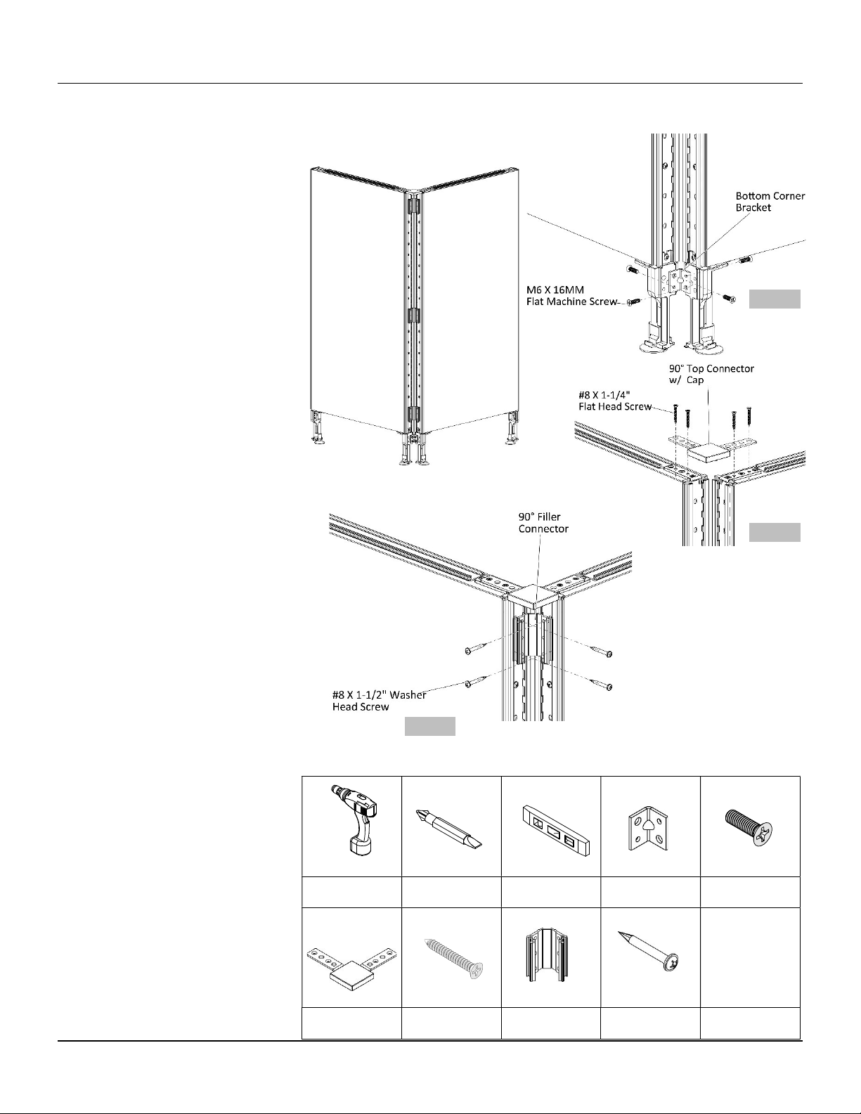
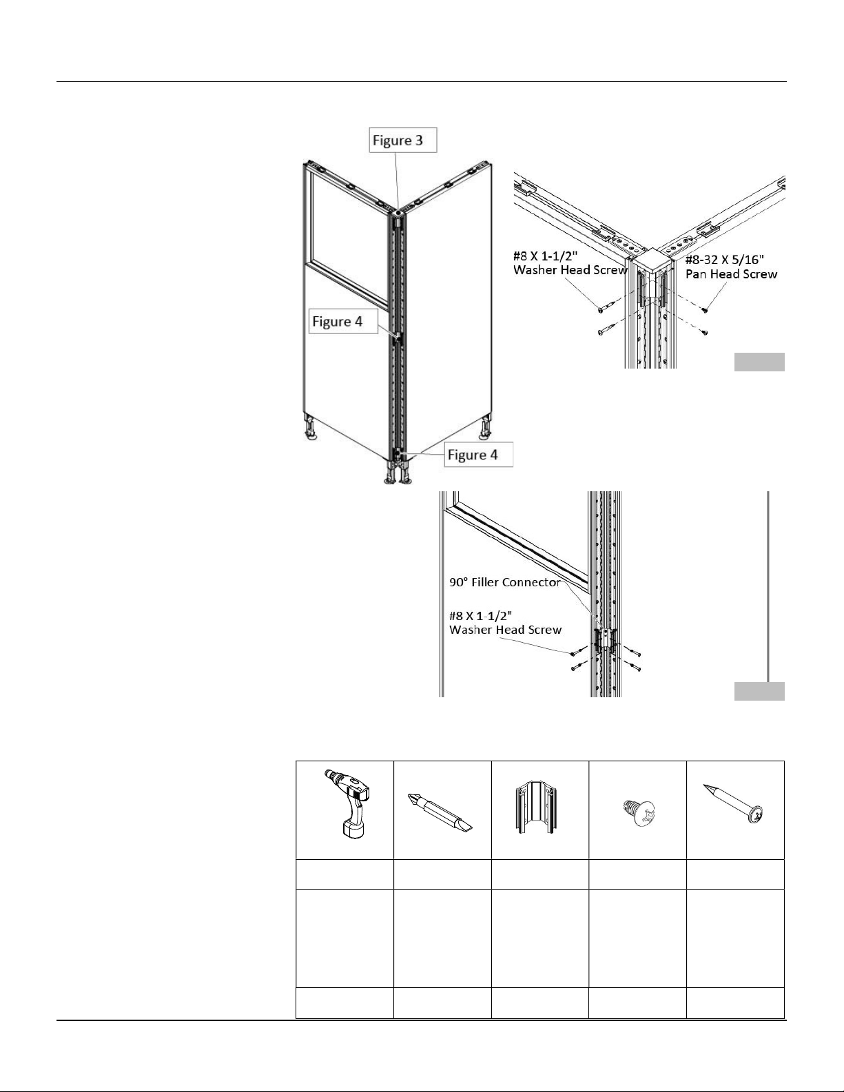
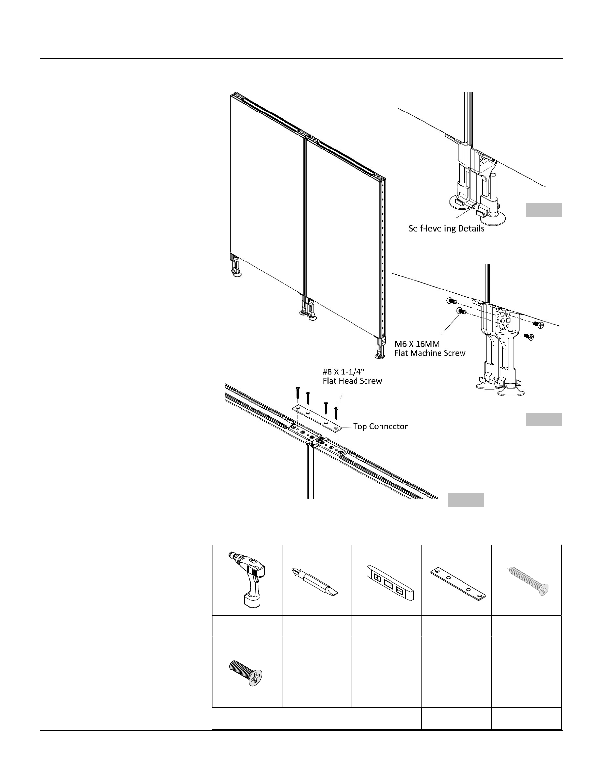
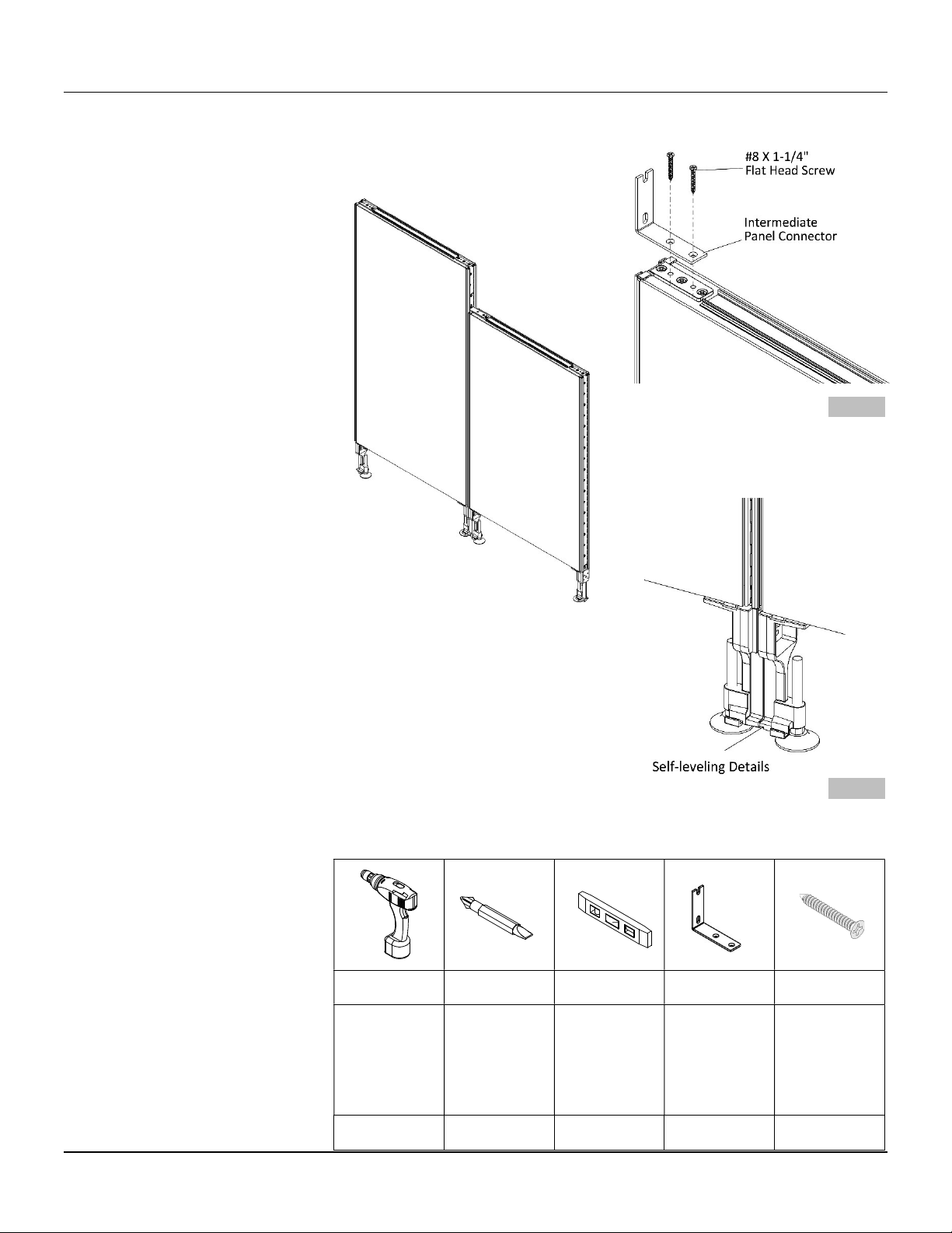
2-Way 90° Panel Connection - Type A..................................................................................... 10
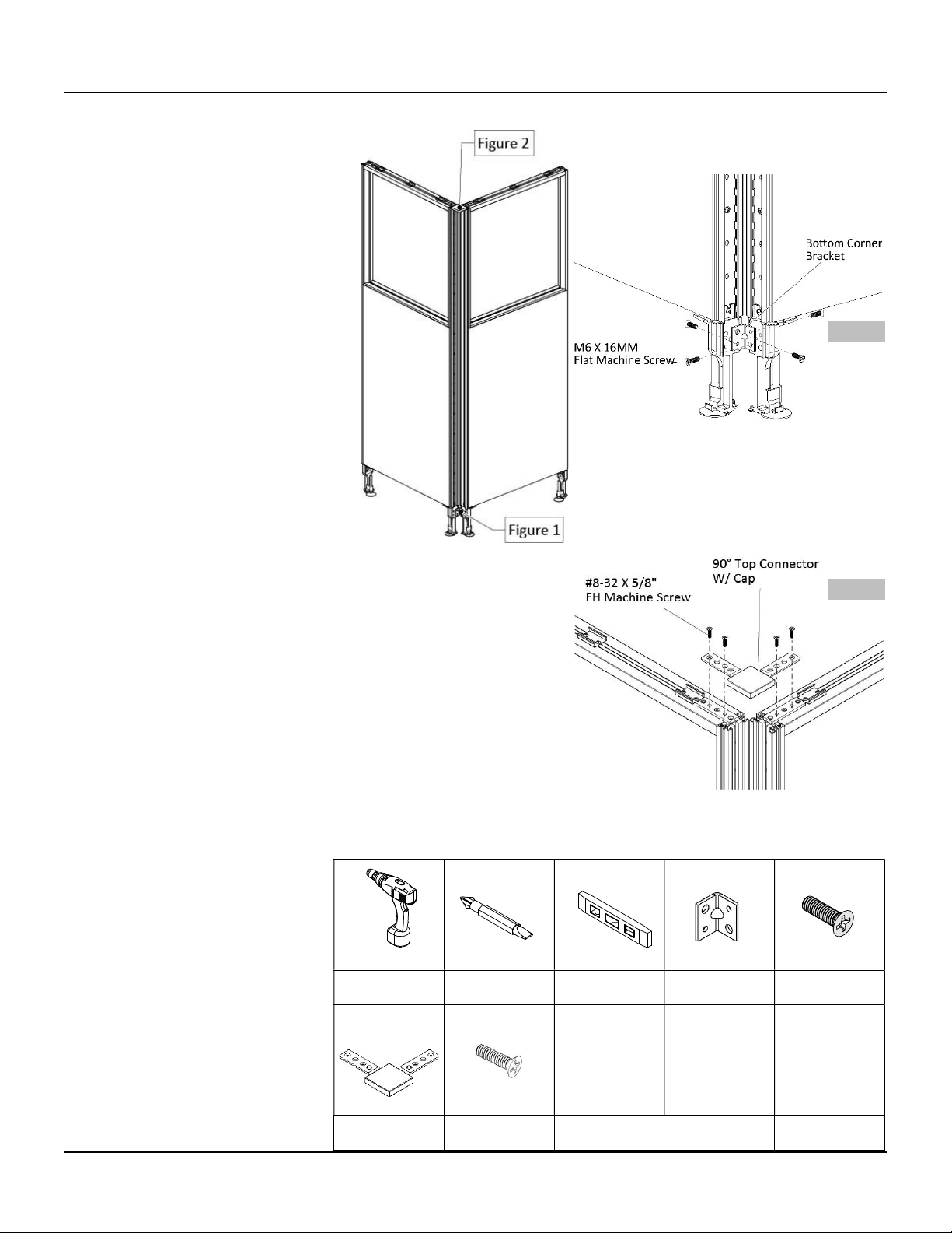
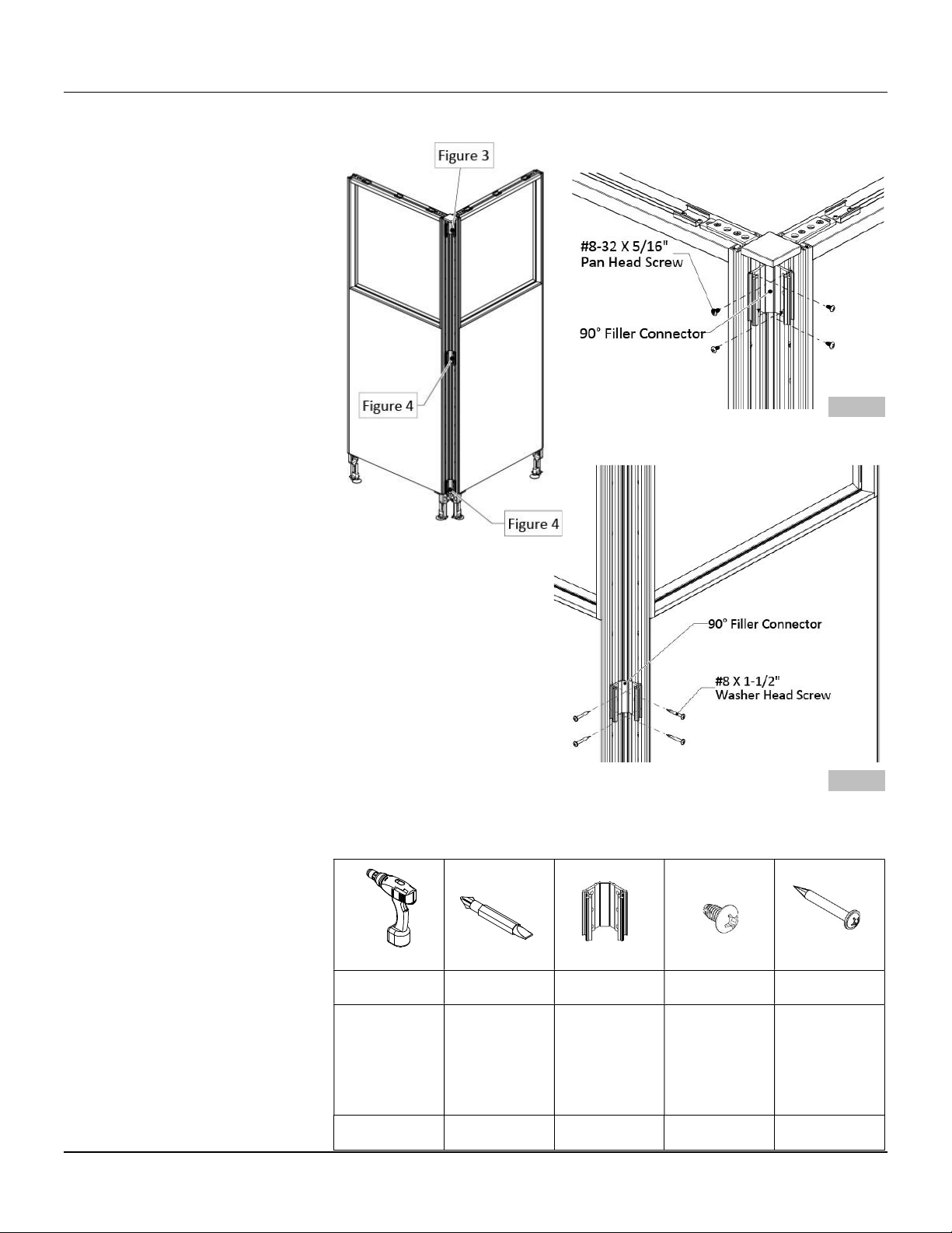
2-Way 90° Panel Connection - Type A (2 glazed panels) ........................................................ 11
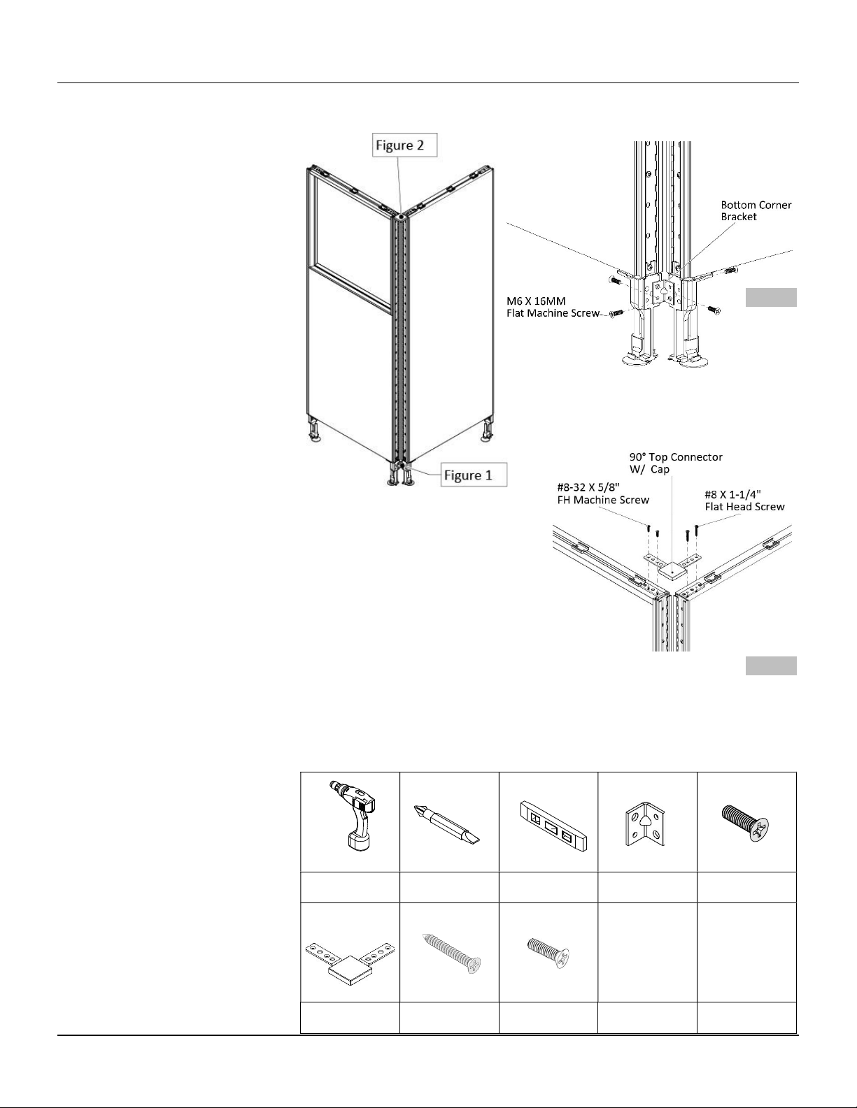
2-Way 90° Panel Connection - Type A (standard & glazed panels) ........................................ 13
2-Way 90° Panel Connection - Type B ..................................................................................... 15
2-Way 180° Panel Connection - Type A .................................................................................. 17
2-Way 180° Panel Connection - Type B ................................................................................... 18
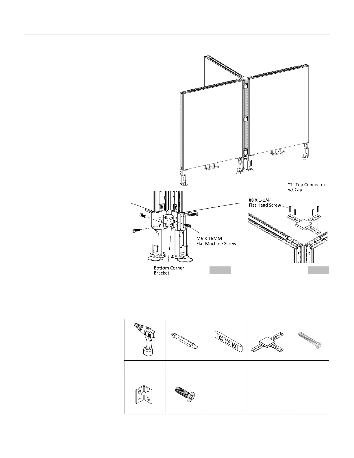
3-Way Panel Connection - Type A ........................................................................................... 20
3-Way Panel Connection - Type B ........................................................................................... 22
3-Way Panel Connection - Type C ........................................................................................... 25
3-Way Panel Connection - Type D ........................................................................................... 28
4-Way Panel Connection - Type A ........................................................................................... 31
4-Way Panel Connection - Type B ........................................................................................... 34
4-Way Panel Connection - Type C ........................................................................................... 38
4-Way Panel Connection - Type D ........................................................................................... 41
Elevated Panel Foot Cap Installation....................................................................................... 45
Machine Screws Removal from Glass or Acrylic Panel ........................................................... 46
Top Trim Installation ............................................................................................................... 47
End Trim Installation ............................................................................................................... 48
90° Filler Installation ............................................................................................................... 49
“T” Filler Installation................................................................................................................ 50
Partial End Trim Filler Installation ........................................................................................... 51
Partial 90° Filler Installation .................................................................................................... 52
Partial “T” Filler Installation .................................................................................................... 53
Top Trim Mid Cap .................................................................................................................... 54
Top Trim Mid Cap with Panel Mounted Glass/Acrylic Screen ................................................ 55
Corner Connector Installation ................................................................................................. 56
Corner Connector Installation with Flipper Cabinet ............................................................... 57
Spline Connector Installation .................................................................................................. 58
Raceway Cover Installation ..................................................................................................... 59
Gallery Panel, Single Span, End, .............................................................................................. 60
Gallery Panel, Double Span, End, 1 Piece................................................................................ 61
Gallery Panel, Double Span, End, 2 Pieces .............................................................................. 63
Gallery Panel, Single Span, Mid ............................................................................................... 65
Gallery Panel, Double Span, Mid, 1 Piece ............................................................................... 67
Gallery Panel, Double Span, Mid, 2 Pieces .............................................................................. 69
Gallery Panel, Single Span Step-down End ............................................................................. 71
Gallery Panel, Double Span Step-down End, 1 Piece .............................................................. 73
Gallery Panel, Double Span Step-down End, 2 Pieces ............................................................ 75
Gallery Panel, Single Span Step-down Mid ............................................................................. 77
Gallery Panel, Double Span Step-down Mid, 1 Piece .............................................................. 80
Gallery Panel, Double Span Step-down Mid, 2 Pieces ............................................................ 83
June 2019
switch 3

Standard Panel Mounted Glass/Acrylic................................................................................... 87
Standard Panel Mounted Glass/Acrylic – Double Span .......................................................... 89
Gallery Panel Mounted Glass/Acrylic installation ................................................................... 91
Worksurfaces, Worksurface Supports and Connections 93|112
Transaction Top Installation .................................................................................................... 93
Cantilever Support for Standard Panel ................................................................................... 95
Cantilever Support for Gallery Panel ....................................................................................... 96
Corner Bracket for Standard Panel ......................................................................................... 97
Reinforcement Bar ................................................................................................................. 98
Split Surface Support for Standard Panel ................................................................................ 99
Split Surface Support for Gallery Panel ................................................................................. 101
Flush Plate ............................................................................................................................. 103
Credenza Worksurface Support ............................................................................................ 104
Ladder Gable Leg to Gallery Panel ........................................................................................ 106
Ladder Gable Leg to Standard Panel ..................................................................................... 107
Laminate Gable Leg to Gallery Panel .................................................................................... 108
Laminate Gable Leg to Standard Panel ................................................................................. 109
Wrap Gable Leg to Gallery Panel .......................................................................................... 110
Wrap Gable Leg to Standard Panel ....................................................................................... 111
Tower Storage to Worksurface Connection .......................................................................... 112
Storage 113|129
Pedestal to Gallery Panel – 24D ............................................................................................ 114
Pedestal to Gallery Panel – 30D ............................................................................................ 115
Pedestal to Standard Panel – 24D ......................................................................................... 117
Underside Pedestal Attachment ........................................................................................... 119
Metal Shelf Installation ......................................................................................................... 120
Cubby Storage Installation .................................................................................................... 122
Shared Overhead Cabinet Installation .................................................................................. 123
Flipper Cabinet Installation ................................................................................................... 124
Open/Hinged Cabinet Installation......................................................................................... 127
Accessories 130|134
Tackboard/Whiteboard ........................................................................................................ 130
Accessory Rail Installation .................................................................................................... 131
Accessories Installation ......................................................................................................... 132
CPU Holder ........................................................................................................................... 133
Electrics & Communication 135|153
Electrical Components and Specifications ............................................................................ 135
Harness Calculation ............................................................................................................... 136
Desktop Power/USB Module ................................................................................................ 137
Power Module, Connector Harness & Communication Kit Installation ............................... 138
Electrical Box Holder Installation ......................................................................................... 141
2-Way Power Pole Installation ............................................................................................. 142
3-Way Power Pole Installation ............................................................................................. 144
4-Way Power Pole Installation ............................................................................................. 146
Gallery Panel, Power Pole Installation ................................................................................. 148
Standard Panel, Power Pole Installation .............................................................................. 151
June 2019
switch 4

Installation Checklist
Perform a site inspection prior to the installation date to check existing site conditions and identify constraints and
limitations that could possibly cause delays or problems during the actual installation.
SITE ACCESSIBILITY
1. Verify existing loading facilities and proximity of loading dock to staging area.
2. Verify if receiving area is accessible by trailer.
3. Verify access to service elevators.
4. Reserve service elevators in advance, if necessary.
SITE PREPARATION
1. Clear all obstacles that could interfere with the installation process.
2. When doing a reconfiguration, ensure that all furniture to be re-used are clear of computers, accessories,
books, papers and all personal effects.
3. Ensure that all live wires and data/communications wires are disconnected prior to installation.
FURNITURE PLANS
1. Labeled furniture plans for installation purposes are located in the hardware box. Ensure that drawings are
complete and handy before beginning installation.
STAGING
1. If damages are noticed upon opening the trailer, these must be noted by the receiver on the Bill of Lading.
Also note any imperfections or missing components discovered while unpacking the furniture. This
information is necessary when requesting for product replacement and shipping claims.
2. Unpack products in the general order of installation (refer to Installation Sequence).
WASTE MANAGEMENT
1. Establish a trash removal area separate from the product staging area.
June 2019
switch 5

Care & Maintenance
Fabrics
To remove dust particles, lightly vacuum the fabric surface. Spills and fluid should be immediately blotted. For minor
fabric stains and marks use water-based fabric solvent, applying light pressure, to lift the dirt and stain. Any use of
water and soaps may harm the fabric, causing water stains and damage to the fabric’s contents. Do not scrub the
fabric with bristle or vacuum brushes as the fabric may pill or tear and the appearance may be permanently affected.
Professional steam cleaning is recommended.
Laminates
Dust laminated surfaces for regular maintenance. Clean any dirt or stain with a damp cloth. Do not use an excessive
amount of water, abrasive cleaners, acids or alkalis and do not scratch or scrape surfaces. For persistent stains and
marks use a commercial cleaner, such as Cabinet Magic® or Countertop Magic®, both manufactured by Magic
American Corporation.
Glazed Screens and Cabinet Doors
Dust glazed screen and cabinet doors regularly to keep surfaces free of dust particles. Clean any dirt or stain with a
damp cloth. Dry the area using a dry paper cloth. The use of fiber cloths or rags is not recommended as loose
particles and debris remaining on the cloth may scratch or harm the acrylic surface. Do not use other chemical
cleaners or window cleaners as their chemical compositions may alter and/or permanently affect the surface
appearance.
Painted Metals
Tayco’s painted metal products are powder-paint-coated. To clean these products, use a damp cloth, using only a
small amount of lukewarm water if necessary. Dry with a clean a dry cloth. To avoid scratching and damaging the
painted surface, do not use hard bristled brushes or abrasive.
THE USE OF HARSH CLEANERS AND CHEMICALS MAY PERMANENTLY ALTER THE PRODUCT FINISH APPEARANCE AND
WILL VOID WARANTY.
June 2019
switch 6

Application Guidelines
Connection Types
Continued on the next page >>
June 2019
switch 7

Application Guidelines
Connection Types
June 2019
switch 8

Application Guidelines
Types of Surfaces
no grommet
with grommet
wireplay
June 2019
switch 9

2-Way 90° Panel Connection – Type A (2 standard panels)
Figure 1
Figure 2
Figure 3
Tools & Hardware Needed
8393-0044
8540-1205
Drill
Phillips #2 & #3 Bit
or Robertson # 2 Torpedo Level
Bottom Corner
Bracket M6 X 16MM Flat
Machine Screw (4X)
8393-0046, 8540-
1188 & 8683-0040
8540-1008
8406-0033 8540-1185
90° Top Connector
with Cap #8 X 1-1/4” Flat
Head Screw (4X) 90° Filler Connector
#8 X 1-1/2" Washer
Head Screw
Caution: Do not use #8 X 1-1/4” Flat
Head Screws and #8 X 1-1/2” Washer
Head Screws on Glass or Acrylic Panel.
Remove machine screws from the glass
or acrylic frame and apply them to the
connector bracket, (See Machine
Screws Removal from Glass or Acrylic
panel).
1. Position the panels to create a 90-
degree angle and level them
accordingly.
2. Securely fasten bottom corner
bracket into panel legs with four
M6 X 16MM Flat Machine Screws,
(Figure 1).
3. Position 90-degree top connector
with cap on top corner of the
panel which is to be connected,
(Figure 2).
Without Power Pole:
Use 90-degree top connector with
cap.
With Power Pole:
Use 2-way power pole bracket,
(See 2-Way Power Pole
Installation).
4. Drive four #8 X 1-1/4” Flat Head
Screws through the holes in 90-
degree top connector with cap
into the panels.
5. Position the 90-degree filler
connector at desired location,
(Figure 3).
6. Securely fasten 90-degree filler
connector to panels with four #8 X
1-1/2" Washer Head Screws.
7. Follow Steps 5 and 6 above to
install the remaining 90-degree
filler connectors.
34 & 42 High Panels – 8X
50
&
66
High Panels
–
12X
34 & 42 High Panels – 2X
50
&
66
High
Panels
–
3X
June 2019
switch 10

2-Way 90° Panel Connection – Type A (2 glazed panels)
Figure 1
Figure 2
Tools & Hardware Needed
8393-0044
8540-1205
Drill
Phillips #2 & #3 Bit
or Robertson # 2 Torpedo Level
Bottom Corner
Bracket M6 X 16MM Flat
Machine Screw (4X)
8393-0046, 8540-
1188 & 8683-0040
8540-1196
90° Top Connector
with Cap #8-32 X 5/8”, FH
Mach. Screw (4X)
Caution: Do not use #8 X 1-1/4” Flat
Head Screws and #8 X 1-1/2” Washer
Head Screws on Glass or Acrylic Panel.
Remove machine screws from the glass
or acrylic frame and apply them to the
connector bracket, (See Machine
Screws Removal from Glass or Acrylic
panel).
1. Position the panels to create a 90-
degree angle and level them
accordingly.
2. Securely fasten bottom corner
bracket into panel legs with four
M6 X 16MM Flat Machine Screws,
(Figure 1).
3. Position 90-degree top connector
with cap on top corner of the
panel which is to be connected,
(Figure 2).
Without Power Pole:
Use 90-degree top connector with
cap.
With Power Pole:
Use 2-way power pole bracket,
(See 2-Way Power Pole
Installation).
4. Drive four #8-32 X 5/8”, Flat Head
Machine Screws through the holes
in 90-degree top connector with
cap into the panels.
Continued on the next page >>
June 2019
switch 11

2-Way 90° Panel Connection – Type A (2 glazed panels)
Figure 3
Figure 4
Tools & Hardware Needed
8406-0033
8540-1209
8540-1185
Drill
Phillips #2 & #3 Bit
or Robertson # 2 90° Filler Connector
#8-32 x 5/16"
PH Screw (4X) #8 X 1-1/2" Washer
Head Screw
Caution: Do not use #8 X 1-1/4” Flat
Head Screws and #8 X 1-1/2” Washer
Head Screws on Glass or Acrylic Panel.
Remove machine screws from the glass
or acrylic frame and apply them to the
connector bracket, (See Machine
Screws Removal from Glass or Acrylic
panel).
5. Position the 90-degree filler
connector at desired location,
(Figure 3).
6. Securely fasten 90-degree filler
connector to panels with #8-32 X
5/16"Pan Head Screws (4X).
7. Position the 90-degree filler
connector at desired location,
(Figure 4).
8. Securely fasten 90-degree filler
connector to panels with four #8 X
1-1/2" Washer Head Screws.
9. Follow Steps 7 and 8 above to
install the remaining 90-degree
filler connectors.
34 & 42 High Panels – 2X
50
&
66
High Panels
–
3X
34 & 42 High Panels – 8X
50
&
66
High Panels
–
12X
June 2019
switch 12

2-Way 90° Panel Connection – Type A (standard & glazed panels)
Figure 1
Figure 2
Tools & Hardware Needed
8393-0044
8540-1205
Drill
Phillips #2 & #3 Bit
or Robertson # 2 Torpedo Level
Bottom Corner
Bracket M6 X 16MM Flat
Machine Screw (4X)
8393-0046, 8540-
1188 & 8683-0040
8540-1008
8540-1196
90° Top Connector
with Cap #8 X 1-1/4” Flat
Head Screw (2X)
#8-32 X 5/8”, FH
Mach. Screw (2X)
Caution: Do not use #8 X 1-1/4” Flat
Head Screws and #8 X 1-1/2” Washer
Head Screws on Glass or Acrylic Panel.
Remove machine screws from the glass
or acrylic frame and apply them to the
connector bracket, (See Machine
Screws Removal from Glass or Acrylic
panel).
1. Position the panels to create a 90-
degree angle and level them
accordingly.
2. Securely fasten bottom corner
bracket into panel legs with four
M6 X 16MM Flat Machine Screws,
(Figure 1).
3. Position 90-degree top connector
with cap on top corner of the
panel which is to be connected,
(Figure 2).
Without Power Pole:
Use 90-degree top connector with
cap.
With Power Pole:
Use 2-way power pole bracket,
(See 2-Way Power Pole
Installation).
4. Drive two #8-32 X 5/8”, Flat Head
Machine Screws through the holes
in 90-degree top connector with
cap into the glazed panel.
5. Drive two #8 X 1-1/4”, Flat Head
Screws through the holes in 90-
degree top connector with cap
into the standard panel.
Continued on the next page >>
June 2019
switch 13

2-Way 90° Panel Connection – Type A (standard & glazed panels)
Figure 3
Figure 4
Tools & Hardware Needed
8406-0033
8540-1209
8540-1185
Drill
Phillips #2 & #3 Bit
or Robertson # 2 90° Filler Connector
#8-32 x 5/16"
PH Screw (2X) #8 X 1-1/2" Washer
Head Screw
Caution: Do not use #8 X 1-1/4” Flat
Head Screws and #8 X 1-1/2” Washer
Head Screws on Glass or Acrylic Panel.
Remove machine screws from the glass
or acrylic frame and apply them to the
connector bracket, (See Machine
Screws Removal from Glass or Acrylic
panel).
5. Position the 90-degree filler
connector at desired location,
(Figure 3).
6. Drive two #8-32 X 5/16" Pan Head
Screws through the holes in 90-
degree filler into the glazed panel.
7. Drive two #8 X 1-1/2" Washer
Head Screws through the holes in
90-degree filler into the standard
panel.
8. Position the 90-degree filler
connector at desired location,
(Figure 4).
9. Securely fasten 90-degree filler
connector to panels with four #8 X
1-1/2" Washer Head Screws.
10. Follow Steps 8 and 9 above to
install the remaining 90-degree
filler connectors.
34 & 42 High Panels – 2X
50
&
66
High Panels
–
3X
34 & 42 High Panels – 8X
50
&
66
High Panels
–
12X
June 2019
switch 14

2-Way 90° Panel Connection – Type B
Figure 1
Figure 2
Tools & Hardware Needed
8393-0041
8393-0042
8540-1188
Drill
Phillips #2 Bit or
Robertson # 2 Top Corner Bracket
Intermediate Panel
Connector #10-24 X 1/4” RH
Screw (4X)
8540-1008
#8 X 1-1/4” Flat
Head Screw (2X)
Caution: Do not use #8 X 1-1/4” Flat
Head Screws and #8 X 1-1/2” Washer
Head Screws on Glass or Acrylic Panel.
Remove machine screws from the glass
or acrylic frame and apply them to the
connector bracket, (See Machine
Screws Removal from Glass or Acrylic
panel).
1. Securely fasten intermediate panel
connector to top connector
bracket with four #10-24 X 1/4”
Round Head Screws, (Figure 1).
2. Position the assembled connector
and bracket on top edge of shorter
panel, (Figure 2).
3. Drive two #8 X 1-1/4" Flat Head
Screws through the holes in top
connector bracket into the frame.
Continued on the next page >>
June 2019
switch 15

2-Way 90° Panel Connection – Type B
Figure 3 Figure 4
Figure 5 Figure 6
Tools & Hardware Needed
8540-1185 8393-0044
Drill
Phillips #2 & #3 Bit
or Robertson # 2 Torpedo Level
#8 X 1-1/2" Washer
Head Screw (2X) Bottom Corner
Bracket
8540-1205
8406-0033 8540-1185 8683-0040
8540-1188
M6 X 16MM Flat
Machine Screw (4X) 90° Filler Connector
#8 X 1-1/2" Washer
Head Screw Top Cap
#10-24 X 1/4”, RH
Screw
Caution: Do not use #8 X 1-1/4” Flat
Head Screws and #8 X 1-1/2” Washer
Head Screws on Glass or Acrylic Panel.
Remove machine screws from the glass
or acrylic frame and apply them to the
connector bracket, (See Machine
Screws Removal from Glass or Acrylic
panel).
4. Position the panels to create 90-
degree angle and level them
accordingly.
5. Securely fasten bottom corner
bracket into the panel legs with
four M6 X 16MM Flat Machine
Screws, (Figure 3).
6. Drive two #8 X 1-1/2" Washer
Head Screws through the holes in
intermediate panel connector into
the taller panel, (Figure 4).
7. Securely fasten top cap with #10-
24 X 1/4" Round Head Screw,
(Figure 5).
8. Position 90-degree filler connector
at desired location, (Figure 6).
9. Securely fasten 90-degree filler
connector to panels with four #8 X
1-1/2" Washer Head Screws.
10. Follow Steps 8 and 9 above to
install the remaining 90-degree
filler connectors.
34 & 42 High Panels – 8X
50
&
66
High Panels
–
12X
34 & 42 High Panels – 2X
50
&
66
High Panels
–
3X
June 2019
switch 16

2-Way 180° Panel Connection – Type A
Figure 1
Figure 2
Figure 3
Tools & Hardware Needed
8393-0040 8540-1008
Drill
Phillips #2 & #3 Bit
or Robertson # 2 Torpedo Level
Top Connector
#8 X 1-1/4”, Flat
Head Screw (4X)
8540-1205
M6 X 16MM Flat
Machine Screw (4X)
Caution: Do not use #8 X 1-1/4” Flat
Head Screws and #8 X 1-1/2” Washer
Head Screws on Glass or Acrylic
Panel. Remove machine screws from
the glass or acrylic frame and apply
them to the connector bracket, (See
Machine Screws Removal from Glass
or Acrylic panel).
1. Engage the two panel legs with
the self-leveling details and level
them accordingly, (Figure 1).
2. Securely fasten the panel legs
with four M6 X 16MM Flat
Machine Screws, (Figure 2).
3. Position the top connector
(countersink face up) at desired
location, (Figure 3).
4. Drive four #8 X 1-1/4" Flat Head
Screws through the holes in top
connector into the panels.
June 2019
switch 17

2-Way 180° Panel Connection – Type B
Figure 1
Figure 2
Tools & Hardware Needed
8393-0050
8540-1008
Drill
Phillips #2 & #3 Bit
or Robertson # 2 Torpedo Level
Intermediate Panel
Connector #8 X 1-1/4”, Flat
Head Screw (2X)
Caution: Do not use #8 X 1-1/4” Flat
Head Screws and #8 X 1-1/2” Washer
Head Screws on Glass or Acrylic Panel.
Remove machine screws from the glass
or acrylic frame and apply them to the
connector bracket (See Machine
Screws Removal from Glass or Acrylic
panel).
1. Position intermediate panel
connector on top edge of shorter
panel, (Figure 1).
2. Drive two #8 X 1-1/4" Flat Head
Screws through the holes in
intermediate panel connector into
the panel.
3. Engage the two panels with the
self-levelling details and level them
accordingly, (Figure 2).
Continued on the next page >>
June 2019
switch 18

2-Way 180° Panel Connection – Type B
Figure 3
Figure 4
Tools & Hardware Needed
8540-1185 8540-1205
Drill
Phillips #2 & #3 Bit
or Robertson # 2 #8 X 1-1/2" Washer
Head Screw (2X) M6 X 16MM Flat
Machine Screw (4X)
Caution: Do not use #8 X 1-1/4” Flat
Head Screws and #8 X 1-1/2” Washer
Head Screws on Glass or Acrylic Panel.
Remove machine screws from the glass
or acrylic frame and apply them to the
connector bracket, (See Machine
Screws Removal from Glass or Acrylic
panel).
4. Securely fasten the panel legs with
four M6 X 16MM Flat Machine
Screws, (Figure 3).
5. Drive two #8 X 1-1/2" Washer
Head Screws through the holes in
intermediate panel connector into
taller panel, (Figure 4).
June 2019
switch 19

3-Way Panel Connection – Type A
Figure 1 Figure 2
Tools & Hardware Needed
8393-0045,8683-
0040&8540-1188
8540-1008
Drill
Phillips #2 & #3 Bit
or Robertson # 2 Torpedo Level
“T” Top Connector
with Cap #8 X 1-1/4”, Flat
Head Screw (4X)
8393-0044
8540-1205
Bottom Corner
Bracket M6 X 16MM Flat
Machine Screw (4X)
Caution: Do not use #8 X 1-1/4” Flat
Head Screws and #8 X 1-1/2” Washer
Head Screws on Glass or Acrylic Panel.
Remove machine screws from the glass
or acrylic frame and apply them to the
connector bracket (See Machine
Screws Removal from Glass or Acrylic
panel).
1. Position two panels to create 90-
degree angle and level them
accordingly.
2. Securely fasten bottom corner
bracket to the panel legs with four
M6 X 16MM Flat Machine Screws,
(Figure 1).
3. Position “T” top connector with
cap on top corner of panels,
(Figure 2).
Without Power Pole:
Use “T” top connector with cap.
With Power Pole:
Use 3-way power pole bracket,
(See 3-Way Power Pole
Installation).
4. Drive four #8 x 1-1/4" Flat Head
Screws through the holes in “T”
top connector with cap into the
panels.
Continued on the next page >>
June 2019
switch 20
Table of contents
Other tayco Indoor Furnishing manuals

tayco
tayco Kip User manual

tayco
tayco Height Adjustable Tables User manual

tayco
tayco The Shield Series User manual

tayco
tayco Norris Series User manual

tayco
tayco Halifax User manual

tayco
tayco One-Touch User manual

tayco
tayco Halifax User manual

tayco
tayco Up User manual

tayco
tayco Metro User manual

tayco
tayco Hanna Series User manual
Popular Indoor Furnishing manuals by other brands

Keter
Keter SPACE WINNER Assembly instructions

Jysk
Jysk ABILDSKOV 3610087 manual

Direct Healthcare Group
Direct Healthcare Group Kirton Encora User instructions

Furniture of America
Furniture of America CM3784SV Assembly instructions

Balkene Home
Balkene Home EVANT 64013 manual

fantastic furniture
fantastic furniture GEO 16 CUBE Assembly instructions