tayco Halifax User manual

Halifax
installation guide
January 2021

for more information, contact Installation Service
toll free I 1.800.675.4092
Mon - Fri I 8:30 am – 5:00 pm EST

Table of Contents
General Instructions 1|03
Installation Checklist ................................................................................................................ 1
Care and Maintenance ............................................................................................................. 2
Application Guide ..................................................................................................................... 3
Desking 4|32
AV Unit Mounted Video Table w/ V-Leg ................................................................................... 4
Low Credenza Mounted Desk, A-Leg ........................................................................................ 7
Low Credenza Mounted Desk, A-Leg w/ Short Gable ............................................................. 13
A-leg Cover with Wire/Cable Pass Through ............................................................................ 19
V-Leg Cover & Wire Guide ...................................................................................................... 21
Integration Box Height Adjustable Table (HAT) ...................................................................... 24
Height Adjustable Table (HAT) Skirt ........................................................................................ 32
Storage 35|46
Gallery Wall and Accent Shelf ................................................................................................. 35
Metal Storage, for Under Hutch .............................................................................................. 40
Multi - Storage Unit ................................................................................................................. 41
PET Side Access Locker ............................................................................................................ 44

Installation Checklist
Perform a site inspection prior to the installation date to check existing site conditions and identify
constraints and limitations that could possibly cause delays or problems during the actual installation.
SITE ACCESSIBILITY
1. Verify existing loading facilities and proximity of loading dock to staging area.
2. Verify if receiving area is accessible by trailer.
3. Verify access to service elevators.
4. Reserve service elevators in advance, if necessary.
SITE PREPARATION
1. Clear all obstacles that could interfere with the installation process.
2. When doing a reconfiguration, ensure that all furniture to be re-used are clear of computers,
accessories, books, papers and all personal effects.
3. Ensure that all live wires and data/communications wires are disconnected prior to installation.
FURNITURE PLANS
1. Labeled furniture plans for installation purposes are located in the hardware box. Ensure that
drawings are complete and handy before beginning installation.
STAGING
1. If damages are noticed upon opening the trailer, these must be noted by the receiver on the Bill
of Lading. Also note any imperfections or missing components discovered while unpacking the
furniture. This information is necessary when requesting for product replacement and shipping
claims.
2. Unpack products in the general order of installation (refer to Installation Sequence).
WASTE MANAGEMENT
1. Establish a trash removal area separate from the product staging area.
January 2021
Halifax
Page 1

Care & Maintenance
Laminates
Dust laminated surfaces for regular maintenance. Clean any dirt or stain with a damp cloth. Do not use
an excessive amount of water, abrasive cleaners, acids or alkalis and do not scratch or scrape surfaces.
For persistent stains and marks use a commercial cleaner, such as Cabinet Magic® or Countertop
Magic®, both manufactured by Magic American Corporation.
Painted Metals
Tayco’s painted metal products are powder-paint-coated. To clean these products, use a damp cloth,
using only a small amount of lukewarm water if necessary. Dry with a clean a dry cloth. To avoid
scratching and damaging the painted surface, do not use hard bristled brushes or abrasive.
THE USE OF HARSH CLEANERS AND CHEMICALS MAY PERMANENTLY ALTER THE PRODUCT FINISH
APPEARANCE AND WILL VOID WARANTY.
January 2021
Halifax
Page 2

SINGLE STORAGE UNIT
2 STORAGE UNITS
3 STORAGE UNITS
4 STORAGE UNITS
5 STORAGE UNITS
STORAGE UNITS W/ INTEGRATION BOX
SHARED STORAGE LEG
SINGLE STORAGE LEG
LEGEND:
Storage l Application Guide
Storage Leg Placement
For storage unit 54” wide and up, attach single storage
leg to the middle in underside of the storage unit.
January 2021
Halifax
Page 3

AV Unit Mounted Video Table, w/ V-Leg
8540-0789_SCREW
Drill
Robertson # 2
#10 X 1" Pan Head
Screw
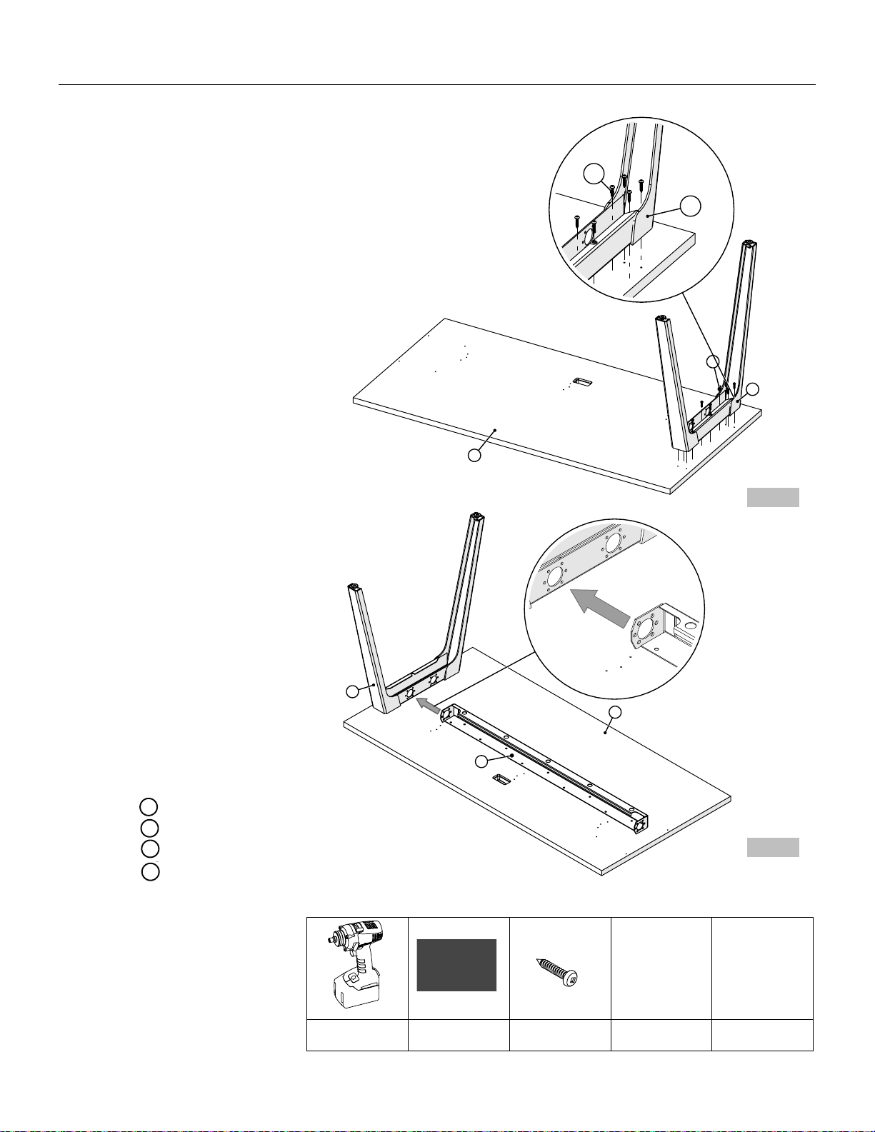
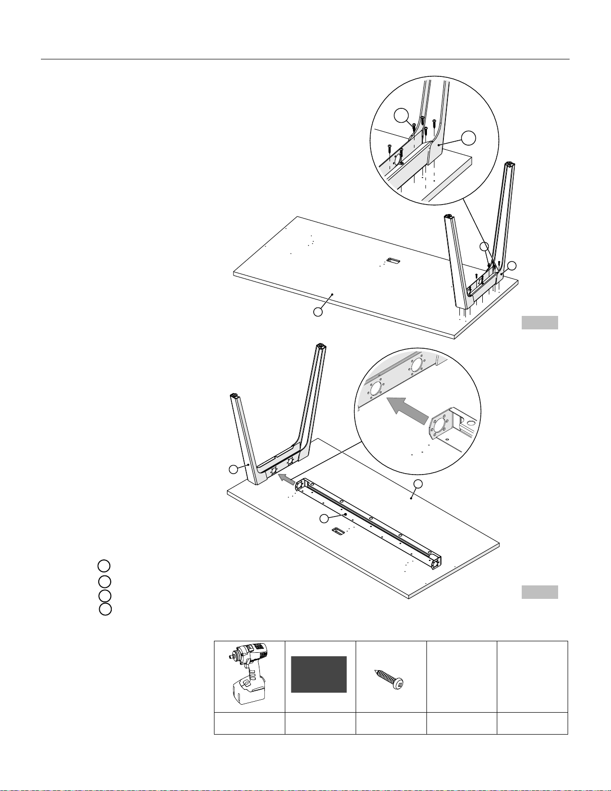
1. Place the worksurface on a
clean, solid surface or floor
with the underside facing
up.
2. Position the V-leg on
underside of worksurface.
Attach the V-Leg by
inserting (18) #10 x 1" Pan
Head Screws into the pre-
drilled holes and tighten,
(Figure 1).
3. Repeat Step 2 to fasten
remaining V-leg.
4. Position the Table Support
Beam on underside of
worksurface using the pre-
drilled positioning holes.
Attach the Table Support
Beam to worksurface
using the #10 x 1" Pan
Head Screws, (Figure 2).
Continued on the next page >>
WORKSURFACE
V-LEG
TABLE SUPPORT BEAM
1
2
3
1
3
P ilot Hole
Pre-drilled holes
2
1
2
Figure 1
Figure 2
January 2021
Halifax
Page 4
AV Unit Mounted Video Table, w/ V-Leg
Tools & Hardware Needed
8540-0789_SCREW
Drill
Robertson # 2
Tape Measure
Torpedo Level
#10 X 1" Pan Head
Screw
6
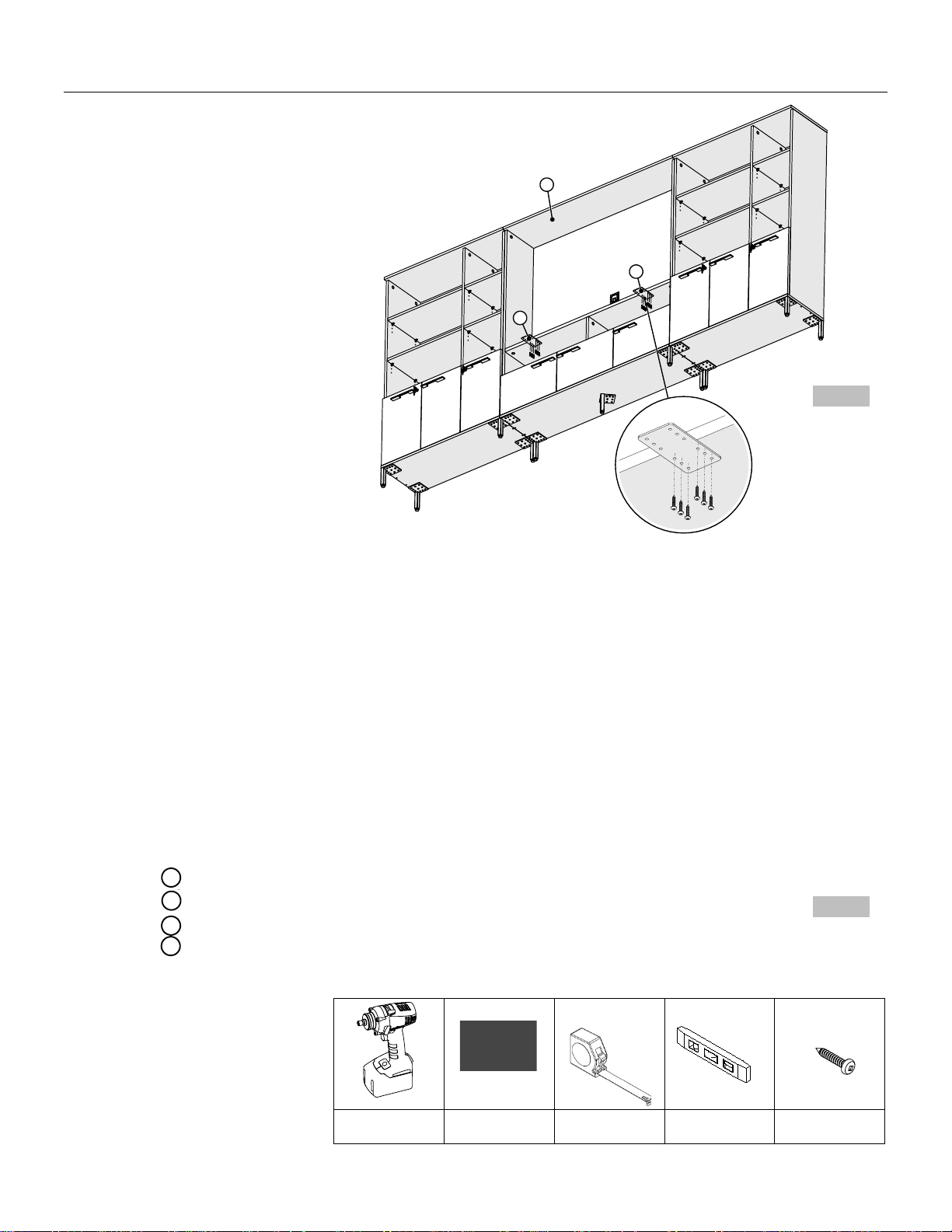
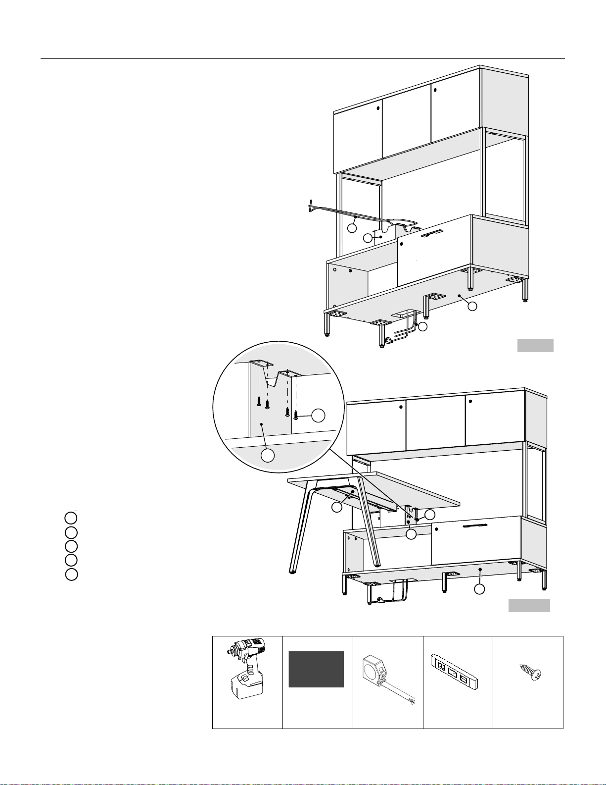
5. Attach the Flush Plate to
underneath the AV
storage unit top fix shelf
using (6) #10 x 1" Pan
Head Screws, (Figure 3).
6. Repeat Step 5 to fasten
remaining flush plate.
7. Carefully turn AV Unit
Mounted Video Table
upright position; Position
AV Unit Mounted Video
Table in the middle of AV
storage unit, (Figure 4).
Continued on the next page >>
5
4
4
5
WORKSURFACE
FLUSH PLATE
AV UNIT MOUNTED VIDEO TABLE
AV STORAGE UNIT
4
1
Figure 4
Figure 3
January 2021
Halifax
Page 5
AV Unit Mounted Video Table, w/ V-Leg
Tools & Hardware Needed
8540-0789_SCREW
Drill
Robertson # 2
Tape Measure
Torpedo Level
#10 X 1" Pan Head
Screw
4
5
4
4
7
9
8
POWER GROMMET
WIRE GUIDE
PLASTIC COVER W/ MAGNETS
7
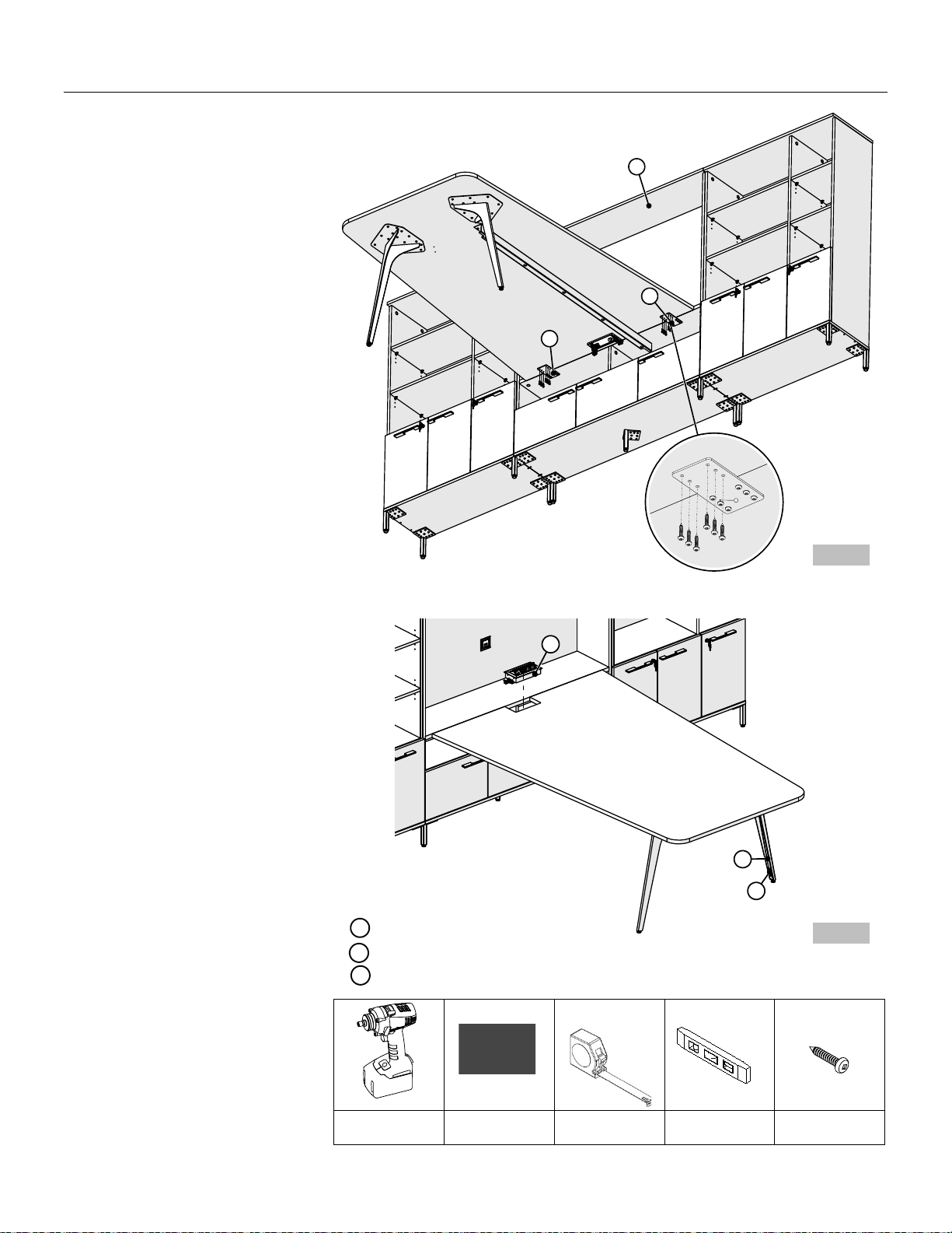
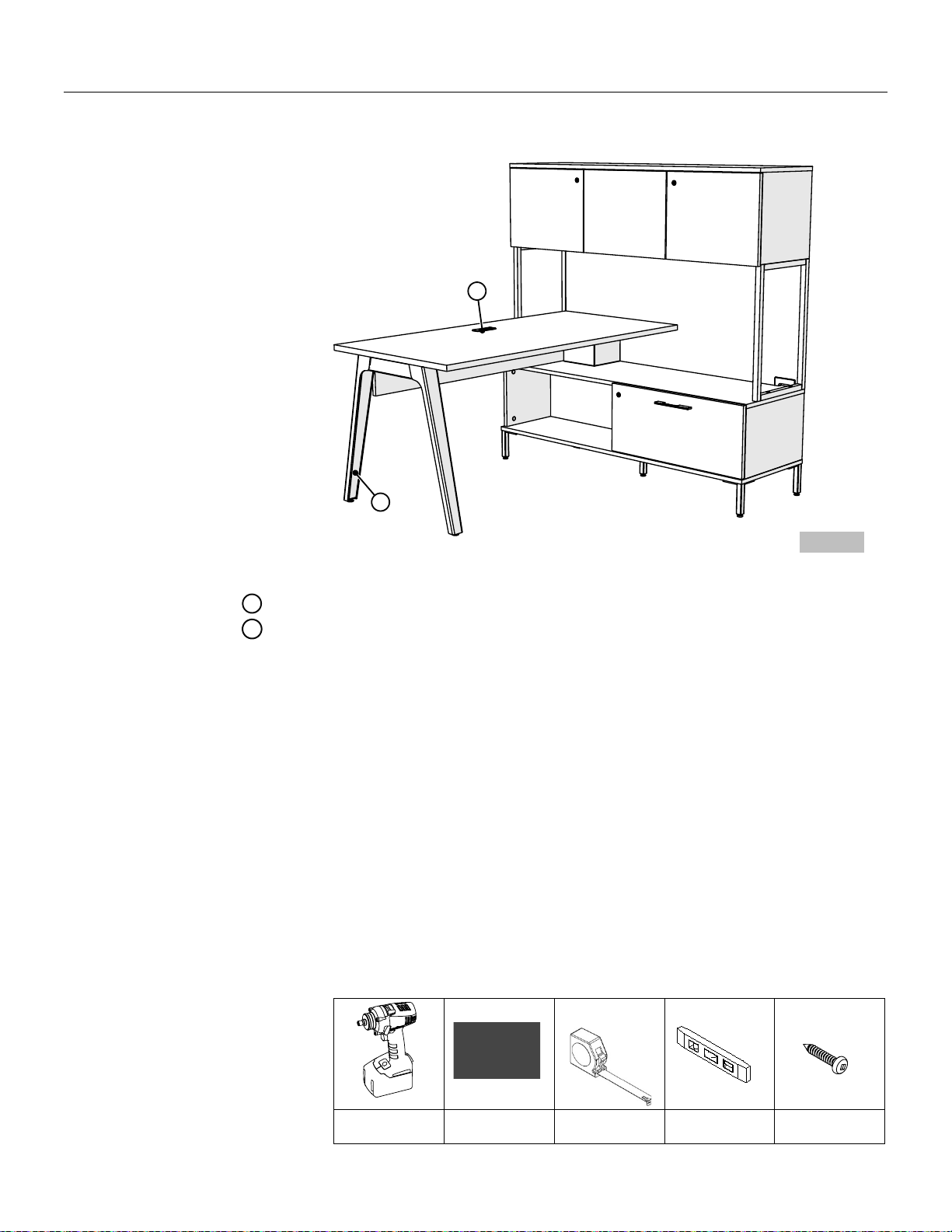
8.
Securely fasten AV Unit
Mounted Video Table to
flush plates using #10 x 1"
Pan Head Screws, (Figure 5).
9. Install the wire guide to V-
leg, please refer to wire
guide and plastic cover
installation for V-leg.
Note: Install the wire guide
to V-leg near the Table
Support Beam.
10.Set the power grommet into
the hole; lay-in the electrical
wires and communication
cables inside wire troughs or
guide.
8
9
Figure 6
Figure 5
January 2021
Halifax
Page 6
1
2
3
2
3
2
1
4
Low Credenza Mounted Desk, A-Leg
8540-0789_SCREW
Drill
Robertson # 2
#10 X 1" Pan Head
Screw
1. Place the worksurface on a
clean, solid surface or floor
with the underside facing up.
2. Position the A-leg over pilot
holes in underside of
worksurface; attach the A-
Leg to worksurface using the
(10) #10 x 1" Pan Head
Screws, (Figure 1).
3. Position table support beam
to A-Leg by aligning the
holes, (Figure 2).
Continued on the next page >>
WORKSURFACE
A-LEG
#10 X 1” PAN HEAD SCREW
TABLE SUPPORT BEAM
1
2
3
4
Figure 1
Figure 2
January 2021
Halifax
Page 7

4
3
1
51
2
4
5
Low Credenza Mounted Desk, A-Leg
Tools & Hardware Needed
8540-0535
8540-0789_SCREW
Drill
Robertson # 2
Tape Measure
1/4-20 x 5/8", Truss
Quad Screw
#10 x 1" Pan Head
Screw
4. Attach the table support
beam to A-Leg using the (6)
1/4-20 x 5/8", Truss Quad
Screw, (Figure 3).
5. Secure the table support
beam to worksurface using
the #10 x 1" Pan Head
Screws, (Figure 4).
Continued on the next page >>
5
WORKSURFACE
A-LEG
#10 X 1” PAN HEAD SCREW
TABLE SUPPORT BEAM
1/4-20 x 5/8", TRUSS QUAD SCREW
4
1
2
3
Figure 4
Figure 3
January 2021
Halifax
Page 8

8
6
7
1
6
7
6
7
8
6
7
Low Credenza Mounted Desk, A-Leg
Tools & Hardware Needed
8540-0528
Drill
Robertson # 2
Tape Measure
#8 x 5/8" Pan Head
Screw
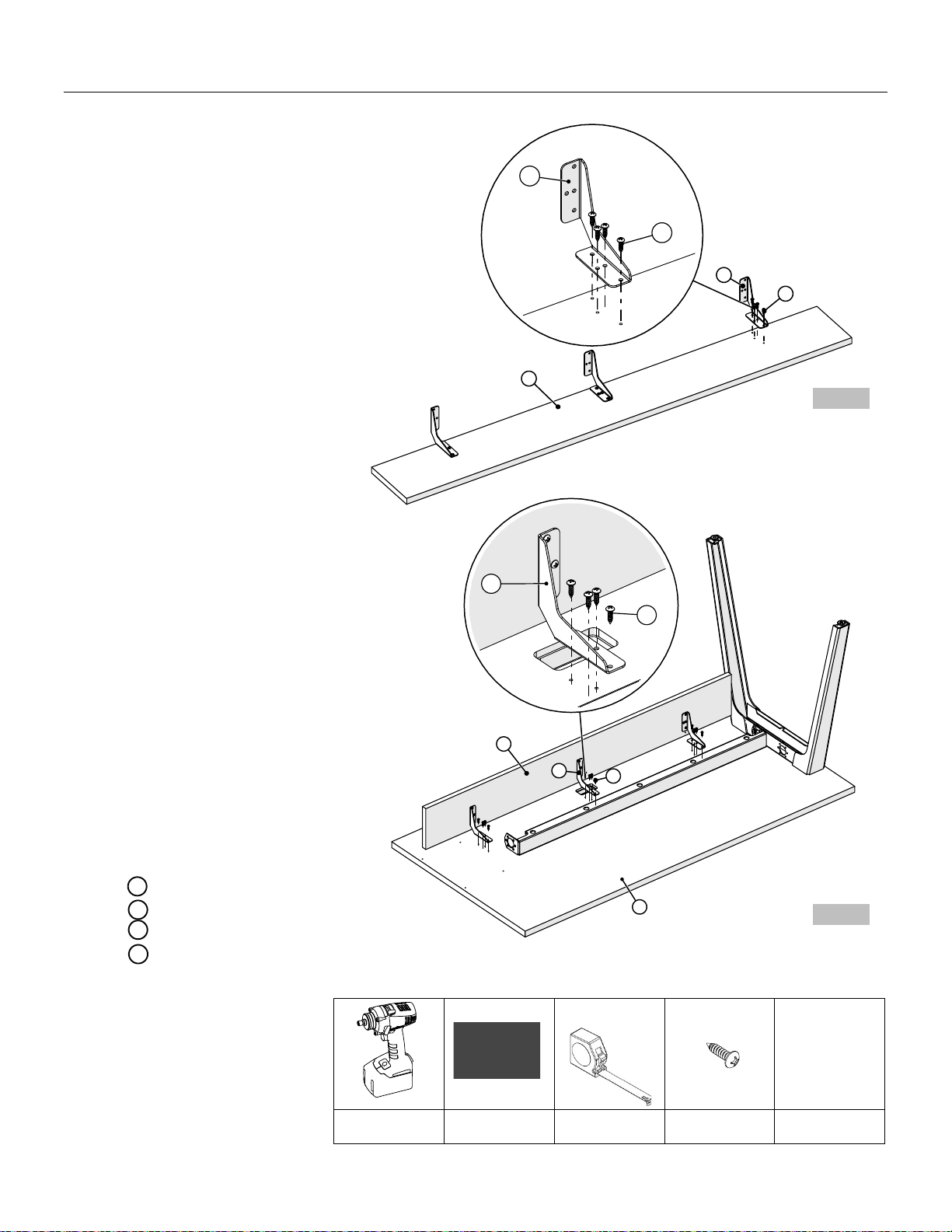
6. Position the cantilever
bracket over pilot holes of
modesty; insert (4) #8 x 5/8”
Pan Quadrex drive screws
per bracket and tighten,
(Figure 5).
7. Position the cantilever
brackets with modesty over
pilot holes in underside of
worksurface; insert (4) #8 x
5/8” Pan Quadrex drive
screws per bracket and
tighten, (Figure 6).
Note: Modesties 60” & wider
comes with 3 brackets
54” and under comes with 2
brackets.
Continued on the next page >>
WORKSURFACE
CANTILEVER BRACKET
#8 x 5/8, PAN QUADREX DRIVE SCREW
MODESTY
1
Figure 5
Figure 6
6
7
8
January 2021
Halifax
Page 9
11
W/ GALLERY WALL
10
13
RH SHOWN
RH SHOWN
RH SHOWN
Low Credenza Mounted Desk, A-LEG
Tools & Hardware Needed
8540-0528
Drill
Robertson # 2
Tape Measure
Torpedo Level
#8 x 5/8" Pan Head
Screw
9
11
7
10
14
11
9
7
10
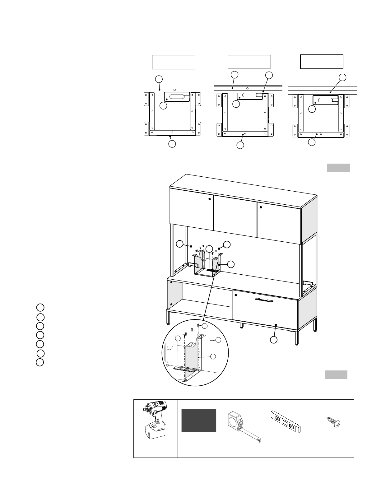
8. Align the desk support box
to the edge of the right-
hand side of the low
credenza grommet; push
desk support box flush with
the hutch back board/PET/
Gallery Wall, (Figure 7).
Note: The open side of desk
support box should be
facing the hutch back
board/PET/ Gallery Wall.
9. Attach the desk support box
to low credenza storage
using the #8 x 5/8, Pan
Quadrex drive, (Figure 8).
Note: In case the layout
includes PET acoustic board,
must be installed before the
desk support box.
Continued on the next page >>
#8 x 5/8” PAN QUADREX DRIVE SCREW
HUTCH BACK BOARD
LOW CREDENZA GROMMET
DESK SUPPORT BOX
PET
GALLERY WALL
LOW CREDENZA STORAGE
7
10
Figure 7
Figure 8
9
W/ HUTCH
9
11
10
12
W/ HUTCH & PET
9
11
10
11
12
13
14
January 2021
Halifax
Page 10
Low Credenza Mounted Desk, A-LEG
Tools & Hardware Needed
8540-0528
Drill
Robertson # 2
Tape Measure
Torpedo Level
#8 x 5/8" Pan Head
Screw
7
11
14
4
7
11
Note: Lay down wires/cables
before installing the surface.
10.Fish wires and cables through
desk support box, (Figure 9).
11.Position desk so it rests on
the desk support box; level
the desk by adjusting the
glides.
12.Attach the worksurface to
desk support metal using the
#8 x 5/8, Pan Quadrex drive
Screw, (Figure 10).
13.Fish wires and cables through
hole of the table support
beam; lay-in the wires and
cables and fish them through
the grommet hole.
Continued on the next page >>
Figure 9
11
15
15
14
Figure 10
TABLE SUPPORT BEAM
#8 x 5/8” PAN QUADREX DRIVE SCREW
DESK SUPPORT BOX
LOW CREDENZA STORAGE
WIRES/CABLES
4
7
14
11
15
January 2021
Halifax
Page 11
Low Credenza Mounted Desk, A-LEG
Tools & Hardware Needed
8540-0789_SCREW
Drill
Robertson # 2
Tape Measure
Torpedo Level
#10 X 1" Pan Head
Screw
14.Attach the A-leg cover,
please refer to A-leg Cover
Installation.
15.Set the grommet into the
grommet hole, (Figure 11).
A-LEG COVER
GROMMET
Figure 11
17
16
16
17
January 2021
Halifax
Page 12
1
2
3
2
3
2
1
4
Low Credenza Mounted Desk, A-Leg w/ Short Gable
8540-0789_SCREW
Drill
Robertson # 2
#10 X 1" Pan Head
Screw
1. Place the worksurface on a
clean, solid surface or floor
with the underside facing up.
2. Position the A-leg over pilot
holes in underside of
worksurface; attach the A-
leg to worksurface using the
(10) #10 x 1" Pan Head
Screws, (Figure 1).
3. Position table support beam
to A-Leg by aligning the
holes, (Figure 2).
Continued on the next page >>
WORKSURFACE
A-LEG
#10 X 1” PAN HEAD SCREW
TABLE SUPPORT BEAM
1
2
3
4
Figure 1
Figure 2
January 2021
Halifax
Page 13

4
3
1
51
2
4
5
Figure 3
Low Credenza Mounted Desk, A-Leg w/ Short Gable
Tools & Hardware Needed
8540-0535
8540-0789_SCREW
Drill
Robertson # 2
Tape Measure
1/4-20 x 5/8", Truss
Quad Screw
#10 x 1" Pan Head
Screw
4. Attach the table support
beam to A-Leg using the (6)
1/4-20 x 5/8", Truss Quad
Screw, (Figure 3).
5. Secure the table support
beam to worksurface using
the #10 x 1" Pan Head
Screws, (Figure 4).
Continued on the next page >>
5
WORKSURFACE
A-LEG
#10 X 1” PAN HEAD SCREW
TABLE SUPPORT BEAM
1/4-20 x 5/8", TRUSS QUAD SCREW
4
1
2
3
Figure 4
January 2021
Halifax
Page 14
8
6
7
1
6
7
6
7
8
6
7
Low Credenza Mounted Desk, A-Leg w/ Short Gable
Tools & Hardware Needed
8540-0528
Drill
Robertson # 2
Tape Measure
#8 x 5/8" Quadrex
Drive Screw
6. Position the cantilever
bracket over pilot holes of
modesty; insert (4) #8 x 5/8”
Pan Quadrex drive screws
per bracket and tighten,
(Figure 5).
7. Position the cantilever
brackets with modesty over
pilot holes in underside of
worksurface; insert (4) #8 x
5/8” Pan Quadrex drive
screws per bracket and
tighten, (Figure 6).
Note: Modesties 60” & wider
comes with 3 brackets
54” and under comes with 2
brackets.
Continued on the next page >>
WORKSURFACE
CANTILEVER BRACKET
#8 x 5/8, PAN QUADREX DRIVE SCREW
MODESTY
1
Figure 5
Figure 6
6
7
8
January 2021
Halifax
Page 15

1
9
10
1
10
9
Figure 9
12
0.75 "
1
13
10
TOP VIEW
7
13
12
11
7
13
12
Figure 7
Figure 8
RH SHOWN
Low Credenza Mounted Desk, A-Leg w/ Short Gable
8540-0528
8540-0770_Dowel
Drill
Robertson # 2
Torpedo Level
#8 x 5/8” Pan QD
Screw
Wooden Dowel
8. Insert the wooden dowels into
the holes of worksurface;
connect the short gable to
worksurface and press the
boards together by inserting
the wooden dowels into the
holes of the short gable,
(Figure 7).
9. Align the desk support box to
the edge of the right-hand side
of the credenza grommet, and
offset 3/4” away from the back
of the low credenza storage,
(Figure 8).
Note: The open side of the
desk support box should be
facing the back or short gable.
10.Attach the desk support box to
low credenza storage using the
#8 x 5/8” Pan Quadrex drive
screws, (Figure 9).
Continued on the next page >>
WORKSURFACE
#8 x 5/8, PAN QUADREX DRIVE SCREW
WOODEN DOWEL
SHORT GABLE
LOW CREDENZA GROMMET
CREDENZA GROMMET
DESK SUPPORT BOX
1
7
9
10
11
13
12
January 2021
Halifax
Page 16

Figure 10
Figure 11
Low Credenza Mounted Desk, A-LEG w/ Short Gable
Tools & Hardware Needed
8540-0545
MENDPLATE-BLK
Drill
Robertson # 2
Tape Measure
Torpedo Level
#10 x 11/16", Oval
Head Screw
Mending Plate
13
14
14
11
3.00 "
15
16
15
16
Note: Lay down wires/cables
before installing the surface.
11.Fish wires and cables through
desk support metal box,
(Figure 10).
12.Position desk so it rests on
the desk support box; level
the desk by adjusting the
glides.
NOTE: Make sure the outer
corner of short gable and
back corner of low credenza
are flush
13.Secure the desk by attaching
the mending plates with
provided #10 x 11/16, Oval
Head Screws, (Figure 11).
Continued on the next page >>
LOW CREDENZA STORAGE
DESK SUPPORT BOX
WIRES/CABLES
MENDING PLATE
#10 X 11/16" OVAL HEAD SCREW
11
14
15
16
13
January 2021
Halifax
Page 17
Other manuals for Halifax
1
Table of contents
Other tayco Indoor Furnishing manuals

tayco
tayco Switch User manual

tayco
tayco Hanna Series User manual

tayco
tayco Scene User manual

tayco
tayco Metro User manual

tayco
tayco Height Adjustable Tables User manual

tayco
tayco Norris Series User manual

tayco
tayco Kip User manual

tayco
tayco The Shield Series User manual

tayco
tayco Halifax User manual

tayco
tayco Up User manual

Popular Indoor Furnishing manuals by other brands

Country Living
Country Living ACS00600 owner's manual

Alice's Home
Alice's Home NOAH IBSAJPUX2 manual

dobue MOVELARIA
dobue MOVELARIA 3000589 Assembly instruction

StyleWell
StyleWell TB8002BK Use and care guide

Mocka
Mocka Lewis Assembly instructions

Aqua Creek Products
Aqua Creek Products SPA LIFT ULTRA manual


