tayco The Shield Series User manual
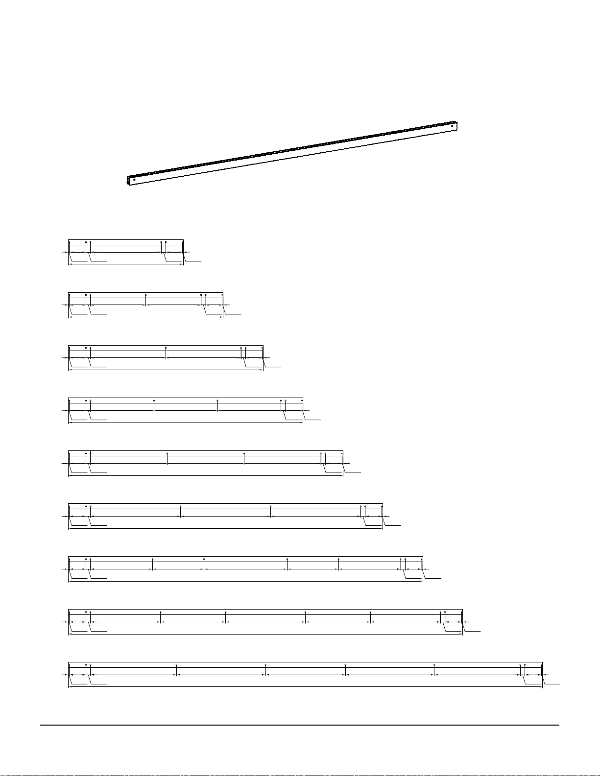
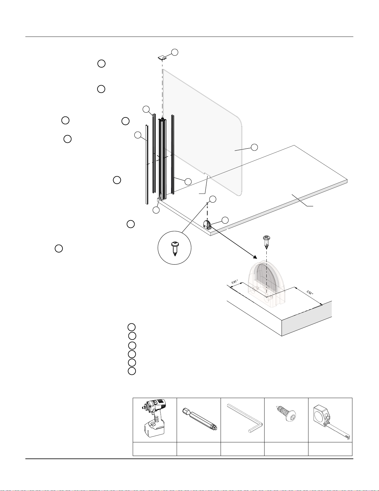
The Shield Collection
installation guide
November 2022

for more information, contact Installation Service
toll free I 1.800.675.4092
Mon - Fri I 8:30 am – 5:00 pm EST
www.tayco.com

TableofContents
GeneralInstructions4|08
InstallationChecklist................................................................................................................4
CareandMaintenance.............................................................................................................5
Caution.....................................................................................................................................6
ApplicationGuides...................................................................................................................7
SceneShields09|16
AcrylicScreenwithPostandFlatBracket.................................................................................9
LaminateScreenwithPostandFlatBracket...........................................................................10
PETScreenwithPostandFlatBracket....................................................................................11
AcrylicScreenwithPostandClamp........................................................................................12
LaminateScreenwithPostandClamp....................................................................................13
PETScreenwithPostandClamp.............................................................................................14
SceneShieldExtendedwithPostfor24”&30”deepSurface................................................15
TransactionShields17|19
TransactionScreenwithPassThru.........................................................................................17
TransactionScreenwithoutPassThru....................................................................................18
TransactionScreenwithCounter............................................................................................19
PanelShield20|20
UniversalBladeScreen............................................................................................................20
GalleryShields21|25
FreestandingShieldwithStationaryWingBase.....................................................................21
GalleryShieldwithDFeet,Laminate......................................................................................22
GalleryShieldwithDFeet,LaminatewithAcrylic..................................................................23
GalleryShieldwithStationaryorMobileSkateFeetLaminate..............................................24
GalleryShieldwithStationaryorMobileSkateFeetLaminatewithAcrylic...........................25

Installation Checklist
Perform a site inspection prior to the installation date to check existing site conditions and identify constraints and
limitations that could possibly cause delays or problems during the actual installation.
SITE ACCESSIBILITY
1. Verify existing loading facilities and proximity of loading dock to staging area.
2. Verify if receiving area is accessible by trailer.
3. Verify access to service elevators.
4. Reserve service elevators in advance, if necessary.
SITE PREPARATION
1. Clear all obstacles that could interfere with the installation process.
2. When doing a reconfiguration, ensure that all furniture to be re-used are clear of computers, accessories,
books, papers and all personal effects.
3. Ensure that all live wires and data/communications wires are disconnected prior to installation.
FURNITURE PLANS
1. Labeled furniture plans for installation purposes are located in the hardware box. Ensure that drawings are
complete and handy before beginning installation.
STAGING
1. If damages are noticed upon opening the trailer, these must be noted by the receiver on the Bill of Lading.
Also note any imperfections or missing components discovered while unpacking the furniture. This
information is necessary when requesting for product replacement and shipping claims.
2. Unpack products in the general order of installation (refer to Installation Sequence).
WASTE MANAGEMENT
1. Establish a trash removal area separate from the product staging area.
November 2022
the shield collection 4

Care & Maintenance
Laminates
Dust laminated surfaces for regular maintenance. Clean any dirt or stain with a damp cloth. Do not use an excessive
amount of water, abrasive cleaners, acids or alkalis and do not scratch or scrape surfaces. For persistent stains and
marks use a commercial cleaner, such as Cabinet Magic® or Countertop Magic®, both manufactured by Magic
American Corporation.
Painted Metals
Tayco’s painted metal products are powder-paint-coated. To clean these products, use a damp cloth, using only a
small amount of lukewarm water if necessary. Dry with a clean a dry cloth. To avoid scratching and damaging the
painted surface, do not use hard bristled brushes or abrasive.
THE USE OF HARSH CLEANERS AND CHEMICALS MAY PERMANENTLY ALTER THE PRODUCT FINISH APPEARANCE AND
WILL VOID WARANTY.
November 2022
the shield collection 5

Caution
LoadBottomDrawerFirst
•Operateonedraweratatime.
•Unitsmaytipifloadedincorrectly.
•Unitsshouldbeattachedtoawallorotherfurnituretoreducetippinghazards.
•Alwaysloadtheheaviestfilesinthebottomdrawer.
HeavyLoad
•Someproductsmustbeanchoredtothewalltoensurestability&safety.
•Itistheownerandinstaller’sresponsibilitytoensurethatthewalltypeandconstructionareofsufficientstrength
tocarryloadsofanywall‐mountedproductsandtheircontents.
•Failureofthewallandanchorstosupportallimposedloadsmayresultinpropertydamageand/orpersonalinjury.
•Taycocanprovidethesizeandemptyweightofitsproductsonly.Awallblockingisconsideredabuilding
constructionprocess,Taycocannotproviderecommendationsinthisrespectandcannotberesponsiblefordamage
orinjurythatmayoccurasaresultofimproperinstallationand/orblocking.
InstabilityHazard
Mobileitemsoncasterssuchasfliptops,personalandmovabletablesofanytype,andstorageitemsofanytypemay
presentaninstabilityhazardifnotsecuredcorrectlywhileinuseorstorage.Flip‐toptablesortrainingtablesofany
typeareinherentlymoreunstablewhenfolded.Taycoprovidesthefollowingguidelines&warningswhenusing
mobileproducts:
•Lockcastersimmediatelyaftermoving.Donotleavethecastersunlockedwheninuseorstorage.
•Motionmayincreasetheinstabilityofanyitemwithcasters.Ifthewheelshitanobstructionthetable’sforward
momentumoftencausesoverturn,especiallyiftheitemisnotequippedwithwheelextensions.Exercisestrong
cautionwhilemovingtheseitems.
•Usecautionwhenabruptlevelchangesinthefloorarepresent(suchasadoorwayorroomthreshold)ascaster
failureortippingmayresult.
•Donotstand,sitorleanonmobileitemsforsupport.Theyarenotintendedforthisuseandpersonalinjuryor
propertydamagemayresult.
•Mobileunitsthatfeatureheight‐adjustableelementsmustbeloweredtotheminimumcompressedheightwhen
movingtopreventinstability.Itisalsorecommendedtheuserremoveallcomputerequipmentorotheraccessories
topreventpossibleweightimbalanceordamagetoequipment.
•Failuretofollowtheguidelinesabovemayresultinpropertydamageorpersonalinjury.
November 2022
the shield collection 6

17.28"
0.15"
2.49"
0.69"
10.63"
0.69"
2.49"
0.15"
23.28"
0.15"
2.49"
0.69"
29.28"
0.15"
2.49"
0.69"
35.28"
0.15"
2.49"
0.69"
9.54" 9.54" 9.54"
0.69"
2.49"
0.15"
41.28"
0.15"
2.49"
0.69"
11.54" 11.54" 11.54"
0.69"
2.49"
0.15"
47.28"
0.15"
2.49"
0.69"
13.54" 13.54" 13.54"
0.69"
2.49"
0.15"
53.28"
0.15"
2.49"
0.69" 0.15"
9.33" 7.73" 12.51" 7.73" 9.33"
0.69"
2.49"
59.28"
0.15"
2.49"
0.69"
10.53" 9.79" 12.00" 9.79" 10.53"
0.69"
2.49"
0.15"
71.28"
0.15"
2.49"
0.69"
12.93" 13.39" 12.00" 13.39" 12.93"
0.69"
2.49"
0.15"
18W
24W
30W
36W
42W
48W
54W
60W
72W
8.31" 8.31"
0.69"
2.49"
0.15"
11.31" 11.31"
0.69"
2.49"
0.15"
Shield ScreensI Application Guide
Blade Extrusion Hole Location
November 2022
the shield collection 7

Shield ScreensI Application Guide
Scene Post Location
23 19.649 20.554 21.460
24 20.649 21.554 22.460
29 25.649 26.554 27.460
30 26.649 27.554 28.460
34 31.649 32.554 33.460
36 32.649 33.554 34.460
40 37.649 38.554 39.460
42 38.649 39.554 40.460
46 43.649 44.554 45.460
48 44.649 45.554 46.460
52 49.649 50.554 51.460
54 50.649 51.554 52.460
58 55.649 56.554 57.460
60 56.649 57.554 58.460
64 61.649 62.554 63.460
66 62.649 63.554 64.460
70 67.649 68.554 69.460
72 68.649 69.554 70.460
SURFACE WIDTH
[inches] Dim A Dim B Dim C
0.136" Dim A 0.136"
SURFACE WIDTH
0.136"
0.136"
0.136"
0.136"
Dim B
SURFACE WIDTH
0.136"
0.770"
0.136"
0.770" Dim C 0.770"
0.136"
SURFACE WIDTH
END TO END
END TO SHARE
SHARE TO SHARE
November 2022
the shield collection 8

Acrylic Screen with Post and Flat Bracket
Figure 1
Tools & Hardware Needed
8540-0599
Drill
Robertson # 2
#8 X 1" Flat Head
Screws (8X)
Tape Measure
6
1
6
SUR FA C E
7
2
6
6
3
1
6
3
6
4
5
7
#8 X 1" FH SC R EW,SQ
1. Install the screen posts
using #8 X 1” Flat Head Screws,
please see Shield Screens
Application Guide to
determine the post location.
2. Slide in the bottom aluminum
bar extrusion within the
posts.
Note: For Raised Screens,
insert the 4” high Post Spacer
Cap Vinyl Retainers first then
the bottom aluminum bar
extrusion.
3. Insert screen vertical vinyl
retainer into the groove of
post until it bottoms out.
4. Insert the acrylic into the
vertical vinyl retainers within
the posts.
5. Place the top aluminum bar
extrusion on top of acrylic.
6.
Install post cap vinyl retainers
to the posts.
7. Snap on the screen post top
caps .
SCREEN POST WITH FLAT BRACKET
BOTTOM ALUMINUM BAR EXTRUSION
SCREEN VERTICAL VINYL RETAINER
ACRYLIC
TOP ALUMINUM BAR EXTRUSION
POST CAP VERTICAL VINYL RETAINER
SCREEN POST TOP CAP
1
2
3
4
5
7
6
1
2
5
6
7
3
4
November 2022
the shield collection 9

Laminate Screen with Post and Flat Bracket
Tools & Hardware Needed
8540-0599
Drill
Robertson # 2
#8 X 1" Flat Head
Screws (8X)
Tape Measure
3
1
3
SUR FA C E
3
1
3
2
3
4
3
4
#8 X 1" FH SC R EW,SQ
1.
Install the screen posts
using #8 X 1” Flat Head
Screws, please see Shield
Screens Application Guide
to determine the post
location.
2. Slide in the laminate
down into the grooves
within the posts until it
bottoms up.
3. Install post cap vinyl
retainers to the posts.
4. Install the screen post top
caps .
SCREEN POST WITH FLAT BRACKET
LAMINATE
POST CAP VERTICAL VINYL RETAINER
SCREEN POST TOP CAP
1
2
3
4
1
2
3
4
November 2022
the shield collection 10

PET Screen with Post and Flat Bracket
Tools & Hardware Needed
8540-0599
Drill
Robertson # 2
#8 X 1" Flat Head
Screws (8X)
Tape Measure
6
1
6
SUR FA C E
7
2
6
3
1
5
6
6
3
6
4
7
#8 X 1" FH SC R EW,SQ
1. Install the screen posts
using #8 X 1” Flat Head
Screws, please see Shield
Screens Application Guide
to determine the post
location.
2. Slide in the bottom
aluminum bar extrusion
within the posts.
3. Insert screen vertical vinyl
retainer into the groove
of post until it bottoms out.
4. Insert the PET screen into
the vertical vinyl retainers
within the posts.
5. Place the top aluminum bar
extrusion on top of
acrylic.
6. Install post cap vinyl
retainers to the posts.
7. Install the screen post top
caps .
SCREEN POST WITH FLAT BRACKET
BOTTOM ALUMINUM BAR EXTRUSION
SCREEN VERTICAL RETAINER
PET SCREEN
TOP ALUMINUM BAR EXTRUSION
POST CAP VERTICAL VINYL RETAINER
SCREEN POST TOP CAP
1
2
3
4
5
7
6
1
2
3
4
5
6
7
November 2022
the shield collection 11

Acrylic Screen with Post and Clamp
Tools & Hardware Needed
Tape Measure
6
1
6
SUR FA C E
7
2
6
6
3
1
6
3
6
4
5
7
1. Fasten the screen posts
in place by clamping them
onto the edge of a surface,
please see Shield Screens
Application Guide to
determine the post
location.
Slide in the bottom
aluminum bar extrusion
within the posts.
Note: For Raised Screens,
insert the 4” high Post
Spacer Cap Vinyl Retainers
first then the bottom
aluminum bar extrusion.
2. Insert screen vertical vinyl
retainer into the groove
of post until it bottoms out.
3. Insert the acrylic into
the vertical vin
yl retainers
within the posts.
4. Place the top aluminum
bar extrusion on top of
acrylic.
5. Install post cap vinyl
retainers to the posts.
6. Install the screen post top
caps .
SCREEN POST WITH CLAMP
BOTTOM ALUMINUM BAR EXTRUSION
SCREEN VINYL VERTICAL RETAINER
ACRYLIC
TOP ALUMINUM BAR EXTRUSION
POST CAP VERTICAL VINYL RETAINER
SCREEN POST TOP CAP
1
2
3
4
5
7
6
1
2
3
4
5
6
7
November 2022
the shield collection 12

Laminate Screen with Post and Clamp
Tools & Hardware Needed
Tape Measure
3
1
3
SUR FA C E
3
3
1
3
2
4
3
4
1. Fasten the screen posts in
place by clamping them onto
the edge of a surface, please
see Shield Screens
Application Guide to
determine the post location.
2.
Slide in the laminate down
into the grooves within the
posts until it bottoms up.
3. Install post cap vinyl
retainers to the posts.
4. Snap on the screen post top
caps .
SCREEN POST WITH CLAMP
LAMINATE
POST CAP VERTICAL VINYL RETAINER
SCREEN POST TOP CAP
1
2
3
4
1
2
3
4
November 2022
the shield collection 13

PET Screen with Post and Clamp
Tools & Hardware Needed
Tape Measure
5
6
1
6
SUR FA C E
7
2
6
6
3
1
6
7
3
6
4
1. Fasten the screen posts in
place by clamping them onto
the edge of a surface, please
see Shield Screens
Application Guide to
determine the post location.
2. Slide in the bottom
aluminum bar extrusion
within the posts.
3. Insert screen vertical vinyl
retainer into the groove
of post until it bottoms out.
4. Insert the PET screen
into the vertical vinyl
retainers within the posts.
5. Place the top aluminum bar
extrusion on top of
acrylic.
6. Install post cap vinyl
retainers to the posts.
7. Snap on the screen post top
caps .
SCREEN POST WITH CLAMP
BOTTOM ALUMINUM BAR EXTRUSION
SCREEN VERTICAL RETAINER
PET SCREEN
TOP ALUMINUM BAR EXTRUSION
POST CAP VERTICAL VINYL RETAINER
SCREEN POST TOP CAP
1
2
3
4
5
7
6
1
2
3
4
5
6
7
November 2022
the shield collection 14

Scene Shield Extended with Post for 24” & 30” deep Surface
Tools & Hardware Needed
8540-0599
Drill
Robertson # 2
#8 X 1" Flat Head
Screws (4X)
Tape Measure
22
SUR FA C E
1
3
1. Install the screen post with
flat bracket using #8 X 1”
Flat Head Screws .
For post with clamp, install it
by clamping them onto the
edge of a surface. Please see
Shield Screens Application
Guide to determine the post
location.
2. Insert screen vertical vinyl
retainer into the groove
of post until it bottoms out.
Continued on the next page >>
SCREEN POST WITH FLAT BRACKET
#8 X 1” FLAT HEAD SCREWS
SCREEN VERTICAL RETAINER
1
2
3
1
2
3
November 2022
the shield collection 15

Scene Shield Extended with Post for 24” & 30” deep Surface
Tools & Hardware Needed
Drill
Robertson # 2
Allen Key
#10 X 11/16" Oval
Head Screws (1X)
Tape Measure
7
SUR FA C E
7
1
7
4
5
8
CUT-OUT
6
3.
Mark the location of the D-
shaped glass clamp .
Note: Ensure the bottom cut-
out of the acrylic and the D-
shaped glass clamp are
aligned before mounting the
clamp to surface.
4. Attach the D-shaped glass
clamp using #10 X 11/16” .
5. Insert the acrylic with square
corners into the vertical
vinyl retainers until it bottoms
out.
Note: Ensure the bottom cut-
out of the acrylic is snug fit on
the D-shaped glass clamp .
6. Tighten the screws of the D-
shaped glass clamp gently
using an allen key until the
glass/acrylic is secured.
7.
Install post cap vinyl retainers
to the post.
8. Snap on the screen post top
caps .
SCREEN POST WITH FLAT BRACKET
D-SHAPED GLASS CLAMP
#10 X 11/16” OVAL HEAD SCREW, SQ
ACRYLIC SCREEN
POST CAP VINYL RETAINER
POST TOP CAP
4
5
7
6
4
5
6
7
4
4
4
8
8
1
November 2022
the shield collection 16

Transaction Screen with Pass Thru
Tools & Hardware Needed
8540-1304
8540-0545
Drill
Robertson # 2
Allen Key
Tape Measure
1/4-20 X 3/8 Flange
Button-Head Screw
#10 X 11/16" Oval
Head Screws
2
1
34
5
6
1. Get the acrylic screen . .
2. Sandwich the acrylic screen
between the “L“ plate
and back plate .
3. Attach the 1/4-20 X 3/8
Flange Button-Head Screws
through the holes of the
back plate .
4. Tighten gently each screw
until the acrylic is
secured.
5. Position the assembled
parts to the middle of
surface .
6. Attach the “L” plate
underneath the surface
using #10 X 11/16” Oval
Head Screw .
ACRYLIC SCREEN
TRANSACTION SCREEN L PLATE
TRANSACTION SCREEN BACK PLATE
1/4-20 X 3/8 Flange Button-Head Screws
SURFACE
#10 x 11/16" OVAL HEAD SCREW, SQ
1
2
3
4
5
2
3
4
5
1
1
6
2
6
3
November 2022
the shield collection 17

Transaction Screen without Pass Thru
Tools & Hardware Needed
8540-1304
8540-0545
Drill
Robertson # 2
Allen Key
Tape Measure
1/4-20 X 3/8 Flange
Button-Head Screw
#10 X 11/16" Oval
Head Screws
5
6
2
1
3
4
1. Get the acrylic screen . .
2. Sandwich the acrylic screen
between the “L“ plate
and back plate .
3. Attach the 1/4-20 X 3/8
Flange Button-Head Screw
s
through the holes of the
back plate .
4. Tighten gently each screw
until the acrylic is
secured.
5. Position the assembled
parts to the middle of
surface .
6. Attach the “L” plate
underneath the surface
using #10 X 11/16” Oval
Head Screw .
ACRYLIC SCREEN
TRANSACTION SCREEN L PLATE
TRANSACTION SCREEN BACK PLATE
1/4-20 X 3/8 Flange Button-Head Screws
SURFACE
#10 x 11/16" OVAL HEAD SCREW, SQ
1
2
3
4
5
2
3
4
5
1
1
6
2
6
3
November 2022
the shield collection 18

Transaction Screen with Counter
Tools & Hardware Needed
8540-1252
Drill
Robertson # 2
Tape Measure
#6 X 1 3/4" Flat
Head Screws
3
2
1
1.
Install the transaction screen.
Please refer to pages 13 & 14
.
2.
Position and align the holes of
transaction counter to the
holes of “L” plate .
3. Attach the transaction
counter using #6 X 1 3/4” Flat
Head Screws to thesurface.
TRANSACTION COUNTER
TRANSACTION SCREEN “L” PLATE
#6 X 1 3/4" FLAT HEAD SCREW,
1
2
3
1
2
3
2
1
3
November 2022
the shield collection 19

Universal Blade Screen
Tools & Hardware Needed
8540-1217
8540-1170
Drill
Robertson # 2
Tape Measure
#8 X 2" Flat Head
Screws
1/4 -20 X 1/4 SS
Screw (4X)
4
5
1
5
3
3
3
2
6
5
3
6
5
1. Check frameless blade
extrusion if there is a Xmas
tree clip on both ends.
2. Position the frameless blade
extrusion to the middle of
top trim.
3. Securely fasten frameless
blade extrusion on top trim
using #8 X 2” Flat Head Self
Drilling Screws .
NOTE: Make sure there is
something solid for the screws
to bite into to secure the
frameless blade extrusion,
please see Shield Screens
Application Guide, Blade
Extrusion Hole Location.
4. Install glass/acrylic with plastic
gasket into the frameless
blade extrusion .
5. Align and secure the
glass/acrylic by inserting 1/4-
20 X 1/4” Socket Set Screw
through each of the holes on
the side of the frameless blade
extrusion using allen key
driver.
6. Tighten gently each side until
the glass/acrylic is centered
and secured.
Note: Do not overtighten.
Check the frameless blade
extrusion if it is straight.
Overtightening set screws will
bend the Frameless Blade
Extrusion outward and end
caps will not fit.
7. Insert the end cap on both
ends of the Frameless Blade
Extrusion then push it down to
X-MAS TREE
FRAMELESS BLADE EXTRUSION
#8 X 2” FLAT HEAD SCREW
GLASS/ACRYLIC WITH PLASTIC GASKET
1/4-20 X 1/4” SOCKET SET SCREW
END CAP
1
2
3
4
1
2
3
4
5
6
1
5
6
1
1
November 2022
the shield collection 20
Table of contents
Other tayco Indoor Furnishing manuals

tayco
tayco One-Touch User manual

tayco
tayco Up User manual

tayco
tayco Norris Series User manual

tayco
tayco Halifax User manual

tayco
tayco Halifax User manual

tayco
tayco Metro User manual

tayco
tayco Switch User manual

tayco
tayco Kip User manual

tayco
tayco Hanna Series User manual

tayco
tayco Height Adjustable Tables User manual
Popular Indoor Furnishing manuals by other brands

Coaster
Coaster 300676 Assembly instructions

BIG FURNITURE WAREHOUSE
BIG FURNITURE WAREHOUSE BS110 manual

Trendteam
Trendteam LINE 866 Series installation instructions

three h
three h UPSIDE instructions

Zenith
Zenith 9819WW Assembly instructions

Home Decorators Collection
Home Decorators Collection Wellford TH0107 Use and care guide