TBB power Energier Apollo Series User manual

Energier Apollo User Manual
TBB Power Co.,Ltd
Energier Apollo series
ALL-IN-ONE for Solar Hybrid-system
Version A1.5
Date: March. 2018

Energier Apollo User Manual
TBB Power Co.,Ltd
WARNING : FIRE HAZARD
SUITABLE FOR MOUNTING ON CONCRETE OR OTHER
NON- COMBUS TIBLE SURFACE ONLY
CAUTION : THE DC AND AC BREAKER MUST HAVE BEEN
TURNED OFF BEFORE SERVICING
MADE IN CHINA
Disclaimer
Unless specially agreed in writing, TBB Power Co., Ltd
Take no warranty as to the accuracy, sufficiency of suitability of any technical or other
information provided in this manual or other documentation.
Assumes no responsibility or liability for loss or damage, whether direct, indirect, consequential
or incidental, which might arise out of the use of such information
TBB offer standard warranty with its products, taking no responsibility for direct or indirect loss
due to equipment failure.

Energier Apollo User Manual
TBB Power Co.,Ltd
About this Manual
This manual describes our product features and provides procedure of installations. This manual
is for anyone intending to install our equipment.
General Instruction
Thanks for choosing our products and this manual were suitable for Energier Apollo.This chapter
contains important safety and operation instructions. Read and keep this User Guide well for later
reference.
The Energier Apollo needs to be installed by professionals and please pay attention to the following
points prior to installation:
1> Please check the input voltage or voltage of battery is same to the nominal input voltage of
this inverter.
2> Please connect positive terminal “+” of battery to “+” input of the inverter.
3> Please connect negative terminal “-” of battery to “-” input of the inverter.
4> Please connect positive terminal “+” of photovoltaic panel to “PV+” input of the inverter.
5> Please connect negative terminal “-” of photovoltaic panel to “PV-” input of the inverter.
6> Please use the shortest cable to connect and ensure the secure connection.
7> While connecting, please secure the connection and avoid short cut between positive terminal
and negative terminal of battery, which will cause damage of battery.
8> Inverter will have high voltage inside. Only authorized electrician can open the case.
9> The inverter WAS NOT designed to use in any life retaining equipment.

Energier Apollo User Manual
TBB Power Co.,Ltd
Index
1.General Safety Instruction.........................................................................................................................1
1.1 Safety Instruction .............................................................................................................................1
1.2 General Precaution ..........................................................................................................................1
1.3 Precaution regarding battery operation........................................................................................1
2.Description of main Function ...................................................................................................................3
2.1 General Description.........................................................................................................................4
2.2 Inverter..............................................................................................................................................5
2.3 Smart Battery Charger.....................................................................................................................5
2.4 Solar charge controller.....................................................................................................................7
2.5 Transfer..............................................................................................................................................7
2.6 Multi battery chemical available ....................................................................................................7
2.7 Manual Equalization .......................................................................................................................8
2.8 Settable Low voltage disconnect level...........................................................................................8
2.9 Weak Grid .........................................................................................................................................8
2.10 Solar mode ......................................................................................................................................8
2.11 Power Save Mode (PS mode)........................................................................................................9
2.12 AEA –automatic energy allocation..............................................................................................9
2.13 Comprehensive Protection............................................................................................................9
2.14 RS485 communication .................................................................................................................10
2.15 RCH remote module (optional device) .....................................................................................10
2.16 Digital Shunt (optional device) ..................................................................................................10
2.17 Cyber (optional device) –System monitor.................................................................................11
2.18 Software configuration................................................................................................................11
2.19 Naming rule..................................................................................................................................11
3.Structure ....................................................................................................................................................13
3.1 Product drawing ............................................................................................................................13

Energier Apollo User Manual
TBB Power Co.,Ltd
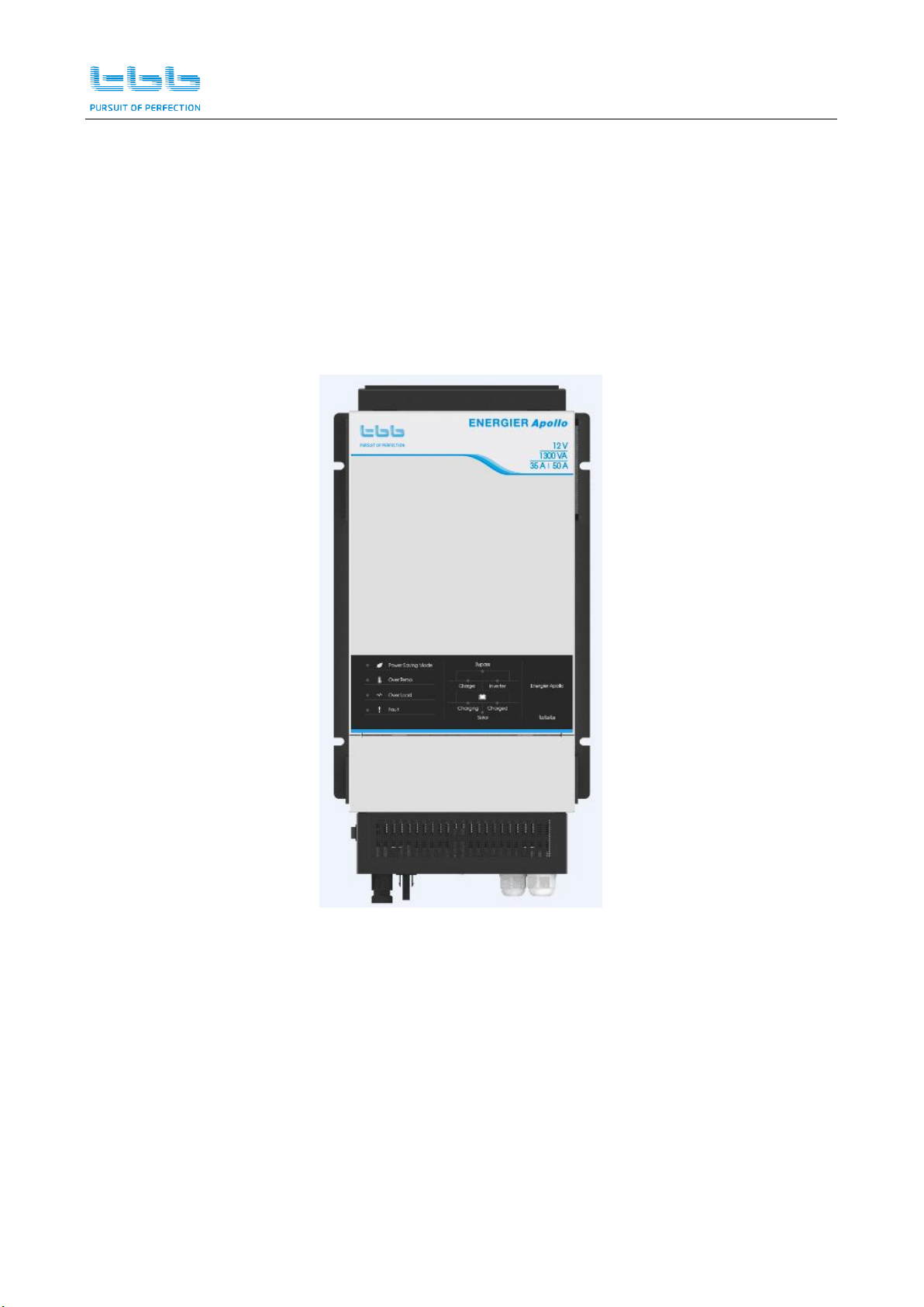
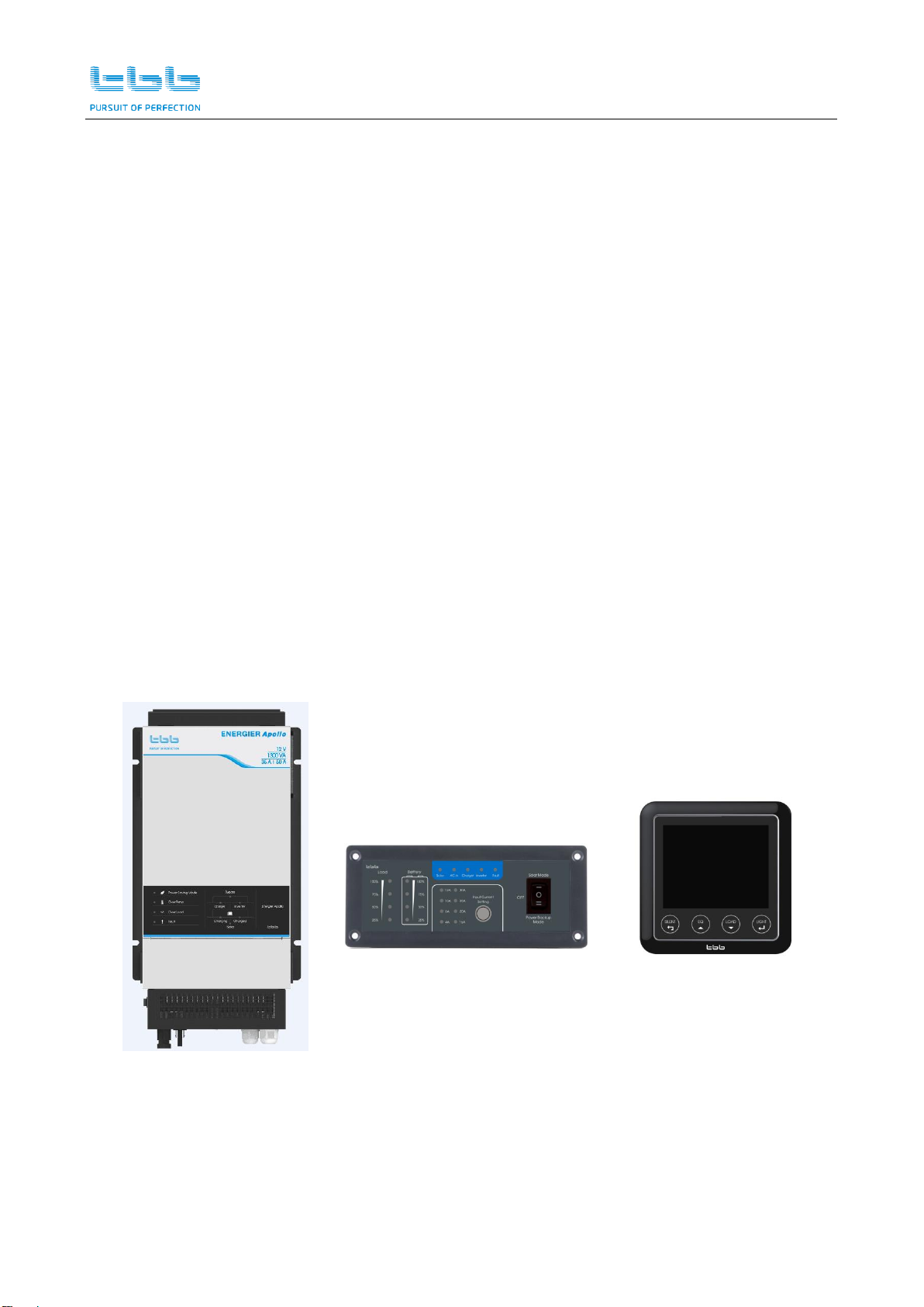
3.1.1 Energier Apollo....................................................................................................................13
3.1.2 RCH remote..........................................................................................................................13
3.1.3 Cyber and Digital Shunt.....................................................................................................13
3.2 Product size ....................................................................................................................................14
3.2.1 Energier Apollo....................................................................................................................14
3.2.2 RCH remote..........................................................................................................................14
3.2.3 Cyber.....................................................................................................................................15
3.2.4 Digital Shunt ........................................................................................................................15
4.Pre-installation Configuration ................................................................................................................16
4.1 Battery Capacity.............................................................................................................................18
4.2 Work Mode .....................................................................................................................................20
4.3 Solar Mode......................................................................................................................................20
4.4 Low Voltage disconnect (LVD).....................................................................................................21
4.5 Battery Type....................................................................................................................................21
4.6 Equalization (EQ)...........................................................................................................................21
4.7 Power Save mode (PS mode)........................................................................................................22
4.8 Grid charger....................................................................................................................................22
4.9 AC input current setting ...............................................................................................................23
5. Pre-Installation.........................................................................................................................................24
5.1 Material list .....................................................................................................................................24
5.2 Location...........................................................................................................................................24
5.3 Wiring recommendation ...............................................................................................................24
6. Installation and Connection ...................................................................................................................25
6.1 General advice................................................................................................................................25
6.2 Fix the equipment ..........................................................................................................................25
6.3 Connecting the cable......................................................................................................................27
6.4 Install the temperature sensor......................................................................................................32
6.5 Install the voltage sensor...............................................................................................................33
6.6 Install the RCH - remote controller..............................................................................................33

Energier Apollo User Manual
TBB Power Co.,Ltd
6.7 Install the Cyber .............................................................................................................................34
6.8 Install the Digital Shunt.................................................................................................................34
6.9 Install the system............................................................................................................................35
6.10 Install the dust-proof net.............................................................................................................35
7.Operation...................................................................................................................................................37
7.1 Double Checking............................................................................................................................37
7.2 Set the AC input .............................................................................................................................37
7.3 Main switch function.....................................................................................................................37
7.4 Switch on the inverter....................................................................................................................38
7.5 Switch on grid charger ..................................................................................................................38
7.6 Switch off grid charger..................................................................................................................39
7.7 Switch on solar charge controller.................................................................................................40
7.8 Switch off solar charge controller ................................................................................................41
7.9 Power Saving mode .......................................................................................................................42
7.10 Performing De-sulphation Charging.........................................................................................42
8.Specification ..............................................................................................................................................46
9.Trouble Shooting ......................................................................................................................................49
9.1 LED indicator on front panel and audible alarm .......................................................................49
9.2 LED indicator on Remote..............................................................................................................50
9.2.1 Operating status...................................................................................................................50
9.2.2 Battery SOC bar ...................................................................................................................51
9.2.3 Load percentage bar............................................................................................................51
9.3 Common failure analysis ..............................................................................................................51
9.3.1 No output first power on....................................................................................................51
9.3.2 No output during operation...............................................................................................52
9.3.3 No charging delivered when you switch on grid input power .....................................53
9.3.4 No charging delivered when you switch on PV input power .......................................53
9.3.5 Normal mode and Power save mode keep changing over.............................................54

Energier Apollo User Manual
TBB Power Co.,Ltd
1
1.General Safety Instruction
1.1 Safety Instruction
As dangerous voltages and high temperature exist within the Energier Apollo, only qualified and
authorized maintenance personnel are permitted to open and repair it. Please make sure Energier
Apollo is turned off before open and repair it.
This manual contains information concerning the installation and operation of the Energier Apollo.
All relevant parts of the manual should be read prior to commencing the installation. Please follow
the local stipulation meantime.
Any operation against safety requirement or against design, manufacture, safety standard, and are
out of the manufacturer warranty.
1.2 General Precaution
1.2.1 Do not expose to dust, rain, snow or liquids of any type,it is designed for indoor use. DO
NOT block off ventilation, otherwise the Energier Apollo would be overheating.
1.2.2 To avoid fire and electric shock,make sure all cables selected with right gauge and being
connected well. Smaller diameter and broken cable are not allowed to use.
1.2.3 Please do not put any inflammable goods near to the unit
1.2.4 Never place unit directly above batteries, gases from a battery will corrode and damage it.
1.2.5 Do not place battery over the unit.
1.3 Precaution regarding battery operation
1.3.1 Use plenty of fresh water to clean in case battery acid contacts skin, clothing, or eyes and
consult with doctor as soon as possible.
1.3.2 The battery may generate flammable gas during charging. NEVER smoke or allow a spark or
flame in vicinity of a battery。
1.3.3 Do not put the metal tool on the battery, spark and short circuit might lead to explosion.

Energier Apollo User Manual
TBB Power Co.,Ltd
2
1.3.4 REMOVE all personal metal items such as rings, bracelets, necklaces, and watches while
working with batteries. Batteries can cause short-circuit current high enough to make metal
melt, and could cause severe burns.

Energier Apollo User Manual
TBB Power Co.,Ltd
3
2.Description of main Function
Thanks for choosing Energier Apollo, of which can be used to compose various hybrid power system.
The product was delivered with following equipment:
Energier Apollo
User’s manual
VS - battery voltage sensor
TS - battery temperature sensor
RCH (Remote module, optional)
Digital Shunt (optional)
Cyber (optional)
IP40 MESH - CHA (optional)
PV EXTENSION - S (optional)
PV EXTENSION - H (optional)
Energier Apollo
RCH
Remote Control Panel
Cyber

Energier Apollo User Manual
TBB Power Co.,Ltd
4
VS
Battery Voltage Sensor
TS
Battery Temperature Sensor
Digital Shunt
2.1 General Description
Energier Apollo is a powerful unit integrated multiple functions, including a high performance true
sine wave inverter, a powerful battery charger, a solar charge controller, a high speed automatic
transfer switch and function of load management, make it very convenient to compose different
solar hybrid system.
++ Working principle

Energier Apollo User Manual
TBB Power Co.,Ltd
5
++ System Work Mode:
Power Backup Mode:
When Energier Apollo is set to “Power Backup Mode”, it will start charging in case AC input is
present. When the AC input is not present, it will switch to inverter mode automatically.
Solar Mode:
When Energier Apollo is set to “Solar Mode”, you can compose a solar hybrid system for your house,
of which solar energy will be used as primary.
2.2 Inverter
++ Pure Sine Wave
Energier Apollo is a sine wave inverter which generates a near perfect sinusoidal AC wave power
output that is very similar or even better to what you could get from your utility grid. Pure sine
wave can guarantee the correct function of sensitive equipment (computer, laser printer, TV etc) or
most demanding inductive load. Also, your home appliances will work smoother, cooler and more
efficient, such as fridge, microwave and power tools.
++ High surge power
Provided with outstanding surge power capability and low frequency transformer, Energier Apollo
is suitable for heavy inductive load like refrigerator, coffee maker, microwave, power tools, air
conditioner etc.
2.3 Smart Battery Charger
The built-in smart battery charger automatically starts up when qualified AC power is presented
either from grid or generator, charging the battery connected.
++ Powerful Charger
The built-in charger of Energier Apollo was designed with high power, which can quickly charge a
battery within 6-8hrs.

Energier Apollo User Manual
TBB Power Co.,Ltd
6
++ Multi stage sophisticated charging algorithm for lead acid battery
Fitted with multistage charging algorithm (bulk-absorption-float-recycle), the built-in charger of
Energier Apollo is designed to charge battery quickly and fully. Microprocessor controlled
charging algorithm with variable absorption charging timer guarantee the optimal charging for
batteries of different discharged state.
Float charging and Recycle charging program guarantee your battery could get proper
maintenance in case of long time connected.
++ Battery temperature compensation
Battery temperature is a key factor in correct charging, the charging formula must be adjusted
(automatically and in real time) according to the actual battery temperature to ensure that battery
are fully charged but not overcharged or undercharged. All charging voltages recommended by
battery manufacture are in fact ONLY applied at 20℃-25℃.
The TS (battery temperature sensor) supplied with Energier Apollo measures the temperature of
battery and automatically makes adjustments at real time to properly charge your batteries at
compensation rate of –4mv/℃/cell. In case of TS was not present, Energier Apollo will use 25℃as
default setting.
++ Voltage compensated charging
Through separately installed the VS (battery voltage sensor), Energier Apollo could automatically
adjust its output compensating the voltage drop on the cable assuring the full charging through
delivering the right voltage to battery.
++ Charger capacity adjustable
Through the clock switch at central panel or through Cyber, user can choose the capacity of battery
you want to charge. According to your choice, Energier Apollo will automatically adjust its output
power makes it suitable the battery capacity selected. The charging current was set at threshold
rate of 15% of battery capacity (I = 0.15C) being set.
++ Lithium battery charging
Energier Apollo can be configured to charge Lithium battery and charging parameter can be

Energier Apollo User Manual
TBB Power Co.,Ltd
7
programmed as well through PC with RapConfig software.
2.4 Solar charge controller
The built-in PWM solar charger controller automatically starts up when qualified PV voltage is
presented from photovoltaic panel, charging the battery connected.
Energier Apollo can charge the battery via AC grid and PV energy at the same time.
The total charging current doesn’t exceed the max charging current you set for the battery
connected.
Charging from PV has higher priority.
2.5 Transfer
In case of voltage, frequency and waveform of AC input match the minimum quality, Energier
Apollo will be switched directly to bypass working mode. Battery charger is switched on and loads
are powered by AC input. You will have the same voltage at the output as AC input.
In case of AC input failure or exceeding the minimum requirement, Energier Apollo will initiate a
quick switching to inverter mode (about 8ms), of which will guarantee an undisturbed power for
majority of the appliance. Upon AC input resume or match the quality, it will switch back again
within 8ms. With this mode (Power Backup Mode), Energier Apollo could be used as an UPS.
Energier Apollo can also be configured working under Solar Mode, please refer to 2.10.
2.6 Multi battery chemical available
Commonly encountered lead acid battery chemicals include AGM, GEL/OPzV, Flooded and Lithium
battery. The voltage required for a proper charging of different battery varies. Energier Apollo could
offer premium charging for above commonly encountered battery categories, of which you can set
through the DIP switch at central panel.
Through Rapconfig software, you could configure the appropriate charging voltage for the battery
installed.

Energier Apollo User Manual
TBB Power Co.,Ltd
8
2.7 Manual Equalization
Over a period of time, the cells in the flooded and OPZS batteries can develop uneven chemical
states. This will result in a weak cell which in turn can reduce the overall capacity of battery. To
improve the life and performance of these types of battery, Energier Apollo includes a manual
equalization program that can be used if recommended by battery manufacturer, to equalize the
battery. For details, please refer to chapter 7.10.
This charging program can ONLY being applied to Flooded and OPZS batteries. As a protection, the
EQ mode will automatically disable if you select either LFP、GEL/OPzV or AGM as battery type.
2.8 Settable Low voltage disconnect level
Deep discharge of the lead acid battery leads to high losses in capacity and early aging. Energier
Apollo continuously supervised and controlled battery condition.
For different application, the user intended to have different low voltage disconnection level. For
example, for solar application, user intended to have less DOD to prolong the battery cycle life. But
for mobile application, user intended to have more DOD to reduce battery capacity and on board
weight.
Through DIP switches, Energier Apollo offer 2 levels of user’s settable low voltage disconnect for
user to configure.
2.9 Weak Grid
With setting at weak grid mode, Energier Apollo will reduce its requirements for AC input (voltage,
frequency and waveform) and pass over the grid to power the load and meantime performing the
charging. Meantime, this mode can be worked in system with generator connected. With this setting,
Energier Apollo can work with majority of generator in the market.
2.10 Solar mode
Under SOLAR Mode, you can use Energier Apollo to compose a solar hybrid system, of which solar
energy will be used as primary. There are two solar hybrid systems for user to choose by dip switch
2.
For details, please refer to chapter 4.3.

Energier Apollo User Manual
TBB Power Co.,Ltd
9
2.11 Power Save Mode (PS mode)
In Power Save mode, the no load power consumption will be reduced by approx 70%. Energier
Apollo will switch off in case of load is less than preset level and will resume after the power reach
the preset level.
2.12 AEA –automatic energy allocation
This function was designed for system with limited input (either grid or generator). It can automatic
allocate the power available with AC source (either grid or genset) using whatever extra for charging,
thus avoiding grid or generator to be overloaded.
2.13 Comprehensive Protection
The equipment is being protected against many failures through hardware and software making it
robust and reliable.
++ Overload protection
Both of charger and output are being protected against overload by software.
In case of the Energier Apollo is too long or too heavily overloaded, it will switch off. After 60secs,
it will switch on automatically. In case of 3times overload shutdown, it will not switch on
automatically. In this case, you need to manually switch on Energier Apollo.
++ Overheat protection
In case of too high internal temperature was detected, Energier Apollo will switch off for overheat
protection. After cooling down, it will switch on automatically.
++ Short circuit
The Energier Apollo will shut down and need manually start.
++ Battery over temp protection
During charging, Energier Apollo will keep monitoring battery temperature and will reduce
charging rate or even shut down upon too high temperature detected. This will help to prevent

Energier Apollo User Manual
TBB Power Co.,Ltd
10
thermal runaway of battery. Energier Apollo will resume charging once the temperature fall into
the scope.
++ Battery Low voltage
User can set its own preferred low voltage disconnect level. Energier Apollo will shut down upon
battery voltage reach the preset level preventing battery to be over-discharged or discharged
exceeding desired level. Once battery voltage raise, Energier Apollo will resume working.
2.14 RS485 communication
RS485/MODBUS was offered in this port. It can be connected to the computer running the
configuration software.
2.15 RCH remote module (optional device)
Through RCH remote module, following information and function can be obtained.
Load percentage monitor
Battery State of Charge monitor
Main switch (Solar Mode / OFF / Power Backup Mode)
System info (Solar, AC input, Charger, Inverter, Fault)
AEA function (AC input current setting)
2.16 Digital Shunt (optional device)
Digital shunt features microprocessor controlled combined with high resolution measuring system
for battery voltage and charge/discharge current. With built in software, it can calculated consumed
AH/KWH and remaining AH/KWH, and display battery voltage and battery current as well.

Energier Apollo User Manual
TBB Power Co.,Ltd
11
Apart from discharging and charging, multiple other factors are considered including battery size,
age ratio of battery etc. With shunt, even the smallest leakage current can be detected and recorded
to guarantee the accuracy.
2.17 Cyber (optional device) –System monitor
In together with Digital Shunt, Cyber can be bought to be
connected to the Energier Apollo for abundant data.
Monitoring : with all real time data
Battery State of Charge monitor
Configuration
Active Alarm info
2.18 Software configuration
Energier Apollo was fully programmable through PC with RapConfig software, of which you
could obtain from us
System
AC source
Battery and Charging
Inverter
Automatic Generator Start
Auxiliary output
2.19 Naming rule
C H X X Y Y Z
Rated output power
Rated charge current
Rated DC voltage
Series name

Energier Apollo User Manual
TBB Power Co.,Ltd
12
field
figure
explanation
CH
series name
XX
10
Rated Output
Power
1000VA/900W
13
1300VA/1200W
16
1600VA/1500W
20
2000VA/1700W
YY
30
Rated charge
current
30A
35
35A
40
40A
50
50A
Z
L
Rated DC voltage
12V
M
24V
CH1350L: Energier Apollo series: Rated DC voltage 12V; Rated output power: 1300VA/1200W;
Rated charge current:50A .
CH2040M: Energier Apollo series: Rated DC voltage 24V; Rated output power: 2000VA/1700W;
Rated charge current:40A .

Energier Apollo User Manual
TBB Power Co.,Ltd
13
3.Structure
3.1 Product drawing
3.1.1 Energier Apollo
CH1035L, CH1350L, CH1630M, CH2040M
3.1.2 RCH remote
3.1.3 Cyber and Digital Shunt
Cyber Digital Shunt

Energier Apollo User Manual
TBB Power Co.,Ltd
14
3.2 Product size
3.2.1 Energier Apollo
CH1035L, CH1350L, CH1630M, CH2040M
3.2.2 RCH remote
122
58
646
130
4-M3 2-φ9.2
70
2-φ4.5
6.75
162
80
56.06
138.08
122
58
646
130
4-M3 2-φ9.2
70
2-φ4.5
6.75
162
80
56.06
138.08
232.5
95
220.5
466.6
220.5
250
95
469.6
Table of contents
Other TBB power Inverter manuals
Popular Inverter manuals by other brands

Innova
Innova 10 HP DC user manual

Generac Power Systems
Generac Power Systems GP1200I owner's manual

Control Techniques
Control Techniques Emerson EV2100 Series user manual

Hyundai
Hyundai HY2000sei user manual

Samlexpower
Samlexpower PST-200S-12A owner's manual

Vector
Vector MAXX SST 1000 VEC049 owner's manual

EINHELL NEW GENERATION
EINHELL NEW GENERATION STE 5000D operating instructions

FoxESS
FoxESS E Series user manual

Pulsar
Pulsar PG4500BiSRCO Operator's manual

Solectria Solar
Solectria Solar Rapid Shutdown Installation and operation guide

Hoymiles
Hoymiles HMS-350-1T-NA user manual

AIR-X
AIR-X LAND 400 owner's manual