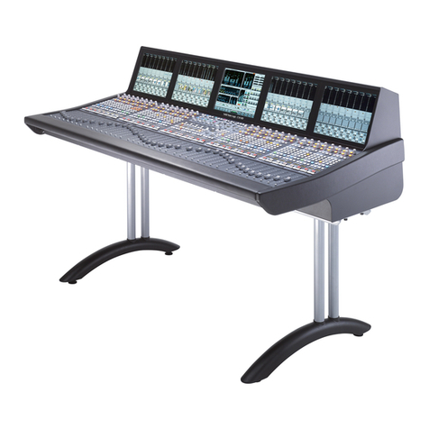
TC Electronic DBMAX - V 2 User manual

DBMAX - V 2
DIGITAL BROADCAST MAXIMIZER
English
USERS MANUAL
All manuals and user guides at all-guides.com
all-guides.com

3
TABLE OF CONTENTS
INTRODUCTION
Table of contents . . . . . . . . . . . . . . . . . . 3
Quick Start Guide . . . . . . . . . . . . . . . . . 4
Introduction . . . . . . . . . . . . . . . . . . . . . . 5
Front Panel . . . . . . . . . . . . . . . . . . . . . . 6
Rear Panel . . . . . . . . . . . . . . . . . . . . . . 8
Signal flow diagram . . . . . . . . . . . . . . . . 9
DBMAX setup . . . . . . . . . . . . . . . . . . . 10
BASIC OPERATION
Reference Levels. . . . . . . . . . . . . . . . . 12
Reference Levels Illustration . . . . . . . . 14
Recall . . . . . . . . . . . . . . . . . . . . . . . . . 15
Store - Delete and Preset Names. . . . . 16
MAIN PAGE
Input . . . . . . . . . . . . . . . . . . . . . . . . . . 18
Inserts
AGC. . . . . . . . . . . . . . . . . . . . . . . . 22
Parametric EQ . . . . . . . . . . . . . . . . 22
90 deg. mono . . . . . . . . . . . . . . . . . 22
Dynamic Equalizer . . . . . . . . . . . . . 24
Stereo Enhance . . . . . . . . . . . . . . . 24
Normalizer . . . . . . . . . . . . . . . . . . . 26
MS Decoding . . . . . . . . . . . . . . . . . 26
MS Encoding . . . . . . . . . . . . . . . . . 26
Expander . . . . . . . . . . . . . . . . . . . . . . 28
Compressor . . . . . . . . . . . . . . . . . . . . 30
Limiter . . . . . . . . . . . . . . . . . . . . . . . . 34
Inserts - Post Dynamic
Transmission Limiter. . . . . . . . . . . . 36
Production Limiter . . . . . . . . . . . . . 36
Output
Dither . . . . . . . . . . . . . . . . . . . . . . . 38
Fade . . . . . . . . . . . . . . . . . . . . . . . 38
Tools
Flow. . . . . . . . . . . . . . . . . . . . . . . . 40
Surround Meter . . . . . . . . . . . . . . . 40
Peak-Hold Meter . . . . . . . . . . . . . . 41
Phase Meter. . . . . . . . . . . . . . . . . . 41
Digital I/O . . . . . . . . . . . . . . . . . . . . 42
Calibration Tone . . . . . . . . . . . . . . . 42
Utility . . . . . . . . . . . . . . . . . . . . . . . . . . 44
Reset page . . . . . . . . . . . . . . . . . . . . . 46
The WIZARD . . . . . . . . . . . . . . . . . . . . 47
APPENDIX
Trouble Shooting . . . . . . . . . . . . . . . . . 48
Self test . . . . . . . . . . . . . . . . . . . . . . . . 49
Technical specifications . . . . . . . . . . . 50
Tutorial . . . . . . . . . . . . . . . . . . . . . . . . 51
Glossary . . . . . . . . . . . . . . . . . . . . . . . 53
Note . . . . . . . . . . . . . . . . . . . . . . . . . . 54
Soldering instructions. . . . . . . . . . . . . . 55
Preset list . . . . . . . . . . . . . . . . . . . . . . 57
Optional Master Fader . . . . . . . . . . . . . 59
All manuals and user guides at all-guides.com

1 Connect analog and/or digital I/O and power to the unit.
The DBMAX will adapt to the power being used in your
area without you ha ing to select a oltage.
2 Turn on the POWER switch at the rear, and press the
POWER key on the front.
3 On LCD IN page 1, select analog, S/PDIF or AES/EBU
Input.
4 Press the REF. LEVELS key and set your I/O
le el conditions:
4.1 If you use analog Inputs or Outputs, adjust the analog le el
required for digital full scale by selecting a proper alue for
the In Le el parameter. When a correct In Le el is selected,
the red LEDs on the INPUT meter should ne er light up,
and indication should be in the -18 to -6dB range.
4.2 Your normal operating le el, typically the le el at which you
would want a calibration tone, may be set as Reference
Le el. In a broadcast en ironment, the Reference Le el
would normally be set 18-20dB below your In Le el. If you
only want to relate to digital full scale, turn the Reference
Le el all the way up.
4.3 The Abs.Peak Output setting determines the maximum
instant peak Output le el from the DBMAX. If you work
against digital peak meters or in transmission, the setting
should be spot on. If you work in an en ironment depending
on analog PPM meters, this setting should be 3-4 dB abo e
the maximum le el allowed with the meter. If you work
against VU meters, the setting should be 12-20dB abo e the
0VU le el.
5. Press the WIZARD key and select the type of limiting/
compression you want by using the PARAMETER keys
and the ADJUST wheel.
QUICK START
6. Press the OK key. Play some program material and lea e
the Wizard working while you are playing a soft part and a
loud part of the type of signal the DBMAX will be
processing. 10 seconds of each will do.
7. Press the OK key again, and the DBMAX has loaded a
best fit parameter setting for your application and source
material.
8. If required, go to the COM block in the MAIN PAGE, and
adjust the More/Less setting to suit your taste. Turning the
control to Less makes the unit beha e as a Limiter.
Turning the control to More makes the unit beha e like a
maximizer.
9. No more o ers. Enjoy!
We recommend you read the entire manual before using the DBMAX, but if you’re anxious to get started we suggest
you take the following steps in the described sequence.
4
All manuals and user guides at all-guides.com

5
INTRODUCTION
Useful features for Production
Le el settings for a number of Radio and TV stations
5-band parametric EQ insert
Stereo Enhancer insert
90º mono insert
MS Decoding insert
MS Encoding insert
Dynamic EQ and De-esser insert
Production Final Limiter pro iding PPM attack response
Production Final Limiter pro iding adjustable Soft-Clip
Dedicated presets for Film and Post Pro Mastering
Dedicated presets for Production Recording
Dedicated presets for CD Mastering
Useful features for Continuity and Transmission
Final TX Limiter pro iding Emphasis compensated HF limiting
Final TX Limiter pro iding adjustable Soft-Clip
RS485 remote control
90º mono insert
AGC insert
Stereo Enhancer insert
5-band parametric EQ insert
Dynamic EQ and De-esser insert
Dedicated presets for Continuity Limiting
Dedicated presets for Continuity AGC (1-5 bands)
Dedicated presets for gentle Transmission processing
Dedicated presets for aggressi e Transmission processing
General features in the DBMAX version 2.02
Versatile multi-band Compressor/Limiter/Expander with switchable architecture between 1 and 5 bands
Minimum distortion algorithms utilizing 24 and 48 bit processing
New Less/More for control of multi-band compression
Processing at any Sample Rate between 32 and 48kHz
Relay bypass of analog I/O on power-down
Unlock detection of digital Input
Audio bandwidth to 24kHz, or ariable lo-pass filtered for FM transmission
24 bit resolution AD and DA con erters and built in optional Sample Rate con erter
Congratulations on the purchase of your new DBMAX.
We hope that you will have as much pleasure using it as we had making it.
The DBMAX V2.02 is the result of hard work by TC Electronics skilled de elopers, based upon the experience of some of the best
qualified transmission engineers in the business. The DBMAX V2.02 is TC Electronics second generation of broadcast compressors.
Stuffed with all the necessary tools, a strong collection of presets as well as a selection of predefined Le el setups, the DBMAX could be a
difficult unit to operate. But nicely wrapped in TCs award winning highly intuiti e design, you will soon be ready to operate it.
We in ite you to ha e your Input/Output and reference le el specifications included in later software releases. Other DBMAX owners will
then ery easily comply with your specifications when deli ering program material to your station or production house.
For suggestions please contact TC Electronic at: info@tcelectronic.com
Please keep informed on the latest updates either via our internet site at www.tcelectronic.com
or contact TC Electronic directly.
All manuals and user guides at all-guides.com

6
FRONT PANEL
INPUT PPM GAIN REDUCTION
METERS
High - Indicating
the max gain
reduction in the two
high freq.bands.
Mid - Indicating the
max gain reduction
in the mid freq.
bands.
Low - Indicating the
max gain reduction
in the two lower
bands.
LIMIT
LEDS
EXPANDER
ACTIVE
INDICATORS
INDICATORS
OVERLOAD LED
Lights up if internal overload
occurs.
INPUT SAMPLE RATE
INDICATOR
48000 Hz
44100 Hz
32000 Hz
MIDI IN LED
MIDI or RS485 receive
indicator.
CARD LED
Indicates presence of a valid
memory card.
ACTIVITY LED
Indicates when a calculation is
performed.
EDITED LED
Indicates that the preset has
been edited.
PC CARD SLOT
Presets may be copied
to/from a standard
PCMCIA/PC-CARD
memory card.
ELECTRONIC POWER
SWITCH
»Easy touch«
Keep pressed for more than
2 seconds to turn device off.
OUTPUT PPM
High resolution meters.
DEFINED OVERLOAD
User defined overload LED.
CLIP LED
Indicates that Output
is clipped.
All manuals and user guides at all-guides.com

7
FUNCTIONS SECTION
MAIN PAGE
This key allows you to edit
the entire signal flow, from
Input to Output.
REF. LEVELS
All I/O levels are set here.
TOOLS
This key gives you access to
a lot of useful tools for opti-
mizing your material.
UTILITY
Security, Timing calculations,
Memory management and
others.
PROGRAM SECTION
RECALL
Recall presets.
STORE
Store and name presets.
WIZARD
The Wizard guides you
thru some of the hard work
of finding the correct set-
tings of essential
parameters.
BYPASS
Bypass the signal
processing.
CONTROL SECTION
OK
Confirm operations
and switch individual blocks on/off.
HELP
Get help on selected display by
pressing the HELP key.
BLOCK
< >
Select which block to edit on the
Main page.
MENU up/down
Vertically oriented menu selector.
PARAMETER < >
Moves horizontally for selection of
parameter to be modified.
BAND < >
Select between the five bands on
the Com/Lim/Exp pages.
On the EQ page, the BAND keys select
which of the five EQ filters are displayed and
ready for modification.
ADJUST wheel
Sets parameter values and
preset numbers.
FRONT PANEL
All manuals and user guides at all-guides.com
all-guides.com

8
IN
PIN2+/PIN3- PIN2+/PIN3-
LEFTLEFT
DI
RIGHTRIGHT
DO
DI
DO
S/PDIF
BALANCED OUTPUTS
BALANCED INPUTS DIGITAL AUDIO
AES/EBU
2
13
RS485 GPI
IN
SYNC
SERIAL NO.
TYPE: V002-B
MADE IN DENMARK
CAUTION
RISK OF ELECTRIC SHOCK
DO NOT OPEN
WARNING
TO REDUCE THE RISK OF FIRE OR ELECTRIC
SHOCK DO NOT EXPOSE THIS EQUIPMENT TO
RAIN OR MOISTURE
AVIS :
RISQUE DE CHOC ELECTRIQUE-NE PAS
THIS CLASS B DIGITAL DEVICE MEETS ALL REQUIREMENTS OF THE
CANADIAN INTERFERENCE-CAUSING EQUIPMENT REGULATIONS AND
COMPLIES WITH PART 15 OF THE FCC RULES.
OPERATION SUBJECT TO CONDITIONS STATED IN THE MANUAL.
OUVRIR.
100-240V 50-60H 20W~AC
R
UL1419
EN 60065
PROFESSIONAL
AUDIO
EQUIPMENT
REAR PANEL
Main
Power
Switch
Balanced
XLR
Inputs
Balanced
XLR
Outputs
Serial No. Word
Clock
Input
AES/EBU
digital
In/Out
S/PDIF
digital
In/Out
RS485
In
Thru
Out
EXTERNAL
CONTROL
Pedal/Fader
Input
NOTES:
To comply with international regulations, we have also added a rear panel POWER switch.
You don’t need to use the POWER switch on the rear panel. Use the front panel POWER switch instead.
Pin 2 is »hot«on all XLR’s (IEC and AES standards). For soldering instructions please refer to page 55.
If you are connecting the DBMAX to unbalanced equipment, you must tie pins 1 and 3 together in the cable
ends away from the DBMAX.
NOTE!
Pins 1 and 3 on the DIN connectors serve as RS485 connection. Therefore, if you are connecting the unit to
other equipment that use these pins, please make sure to use 3-wire standard MIDI type cable (not a five
wire MIDI-PLUS type).
If you want to use the Pedal Input, make sure it is a momentary type.
Power
Input
All manuals and user guides at all-guides.com

ANALOG
INPUTS
[balanced]
DBMAX
Trim Input
Internal 44.1kH
Internal 48kH
Ext. DI
Clock
Ext. Sync
In Level
Out Fine L/R
Trim Output
ANALOG
OUTPUTS
[balanced]
A/D
INPUT PPM OUTPUT PPM
Defined Overload
Left
Left Left
Right
Bypass
Fader
Right
Right
Input
Selector
Digital Output
[AES]
Digital Input
[AES] AES/EBU
S/PDIF
Digital Output
[S/PDIF]
Digital Input
[S/PDIF]
EXP COMP LIM
Dither
D/A
Ins 4
Ins 1 Ins 2 Ins 3
Digital In Gain
Digital Out Gain
SRC
9
SIGNAL FLOW
All manuals and user guides at all-guides.com

10
DBMAX SETUP
The DBMAX is carefully designed to optimize or limit the o erall le el and enhance the energy in your material.
The use of the fi e band Compressor, Limiter and Expander makes the dynamics section of the DBMAX ery flexible, while
maintaining the fidelity of the original material. The dynamics section, in combination with a Normalizer, AGC, EQ, De-esser
etc. makes the DBMAX a ery powerful tool for optimizing the current signal.
Because the DBMAX can be used in different applications, we propose a few different setups.
Radio Production Transmission applications
DAB production or FM Production suite
The two applications for the DBMAX in this configuration are:
1. The DBMAX can be inserted pre master, to optimize the production.
2. The DBMAX can be inserted post master to emulate the signal processing in transmission.
Transmission
The two applications for the DBMAX in a transmission situation:
1. Digital Broadcast: DBMAX optimizing, limiting and equalizing the signal for digital Audio Broadcast.
2. FM broadcast: DBMAX optimizing, limiting and equalizing the signal in proportion to the current pre-emphasis.
All manuals and user guides at all-guides.com

11
TV Production Transmission applications
Surround Production Suite
The two applications for the DBMAX in this configuration are:
1. The DBMAX can be inserted pre master, to optimize the production.
Note: Adjusting the L/R balance can cause serious changes to the surround encoded signal.
2. The DBMAX can be inserted post master to emulate the signal processing in transmission.
TV continuity/Transmission
The two applications for the DBMAX in a transmission situation are:
1. Digital Sound: DBMAX optimizing, limiting and equalizing the signal for NICAM (or other systems) using the
wordclock as ext. sync.
2. FM Sound: DBMAX optimizing, limiting and equalizing the signal in proportion to the current pre-emphasis,
generating mono (0º or 90º).
DBMAX SETUP
All manuals and user guides at all-guides.com

12
REFERENCE LEVELS
The Reference level settings are the heart of the
DBMAX. If these parameters are not set properly, the
DBMAX may not perform correctly. So please take the
time to go through these level settings and make sure
they are set correctly.
The DBMAX is prepared to match se eral different predefined
Reference Le el setups. These setups could be considered as
le el presets. In addition to these presets you can store four
setups of your own.
Basic operation
- Use the MENU keys to select parameter.
- Use the ADJUST wheel to change alue.
Setup
Load Setup
- Select Load Setup by pressing the grey OK key, and
scroll through the list using the MENU keys.
- Select an en ironment/application resembling your own,
and press OK.
Save Setup
It is possible to store four different custom user setups.
- Place the cursor next to Sa e Setup using the MENU keys.
- Press OK and use the MENU keys to select the location where
you want to store the setup.
- Confirm with OK to store the preset with the same name or
change the name before storing.
To change the name before storing:
- Use the PARAMETER keys to select letter-position and the
ADJUST wheel to select letter.
- When you ha e the desired name in the display, press OK to
store the setup with the new name.
All parameters in Ref. Le els will be sa ed.
Operating Levels
General advice
If you use analog Inputs or Outputs, first adjust the analog le els
In Le el setting to define the analog le el for digital full scale (FS).
The Ref. Le els setting should be adjusted for
nominal signal le el, which is both expressed in dBFS (digital) and
dBu (analog). The Abs. Peak max setting should be adjusted for
maximum instant peak permitted Output le el.
All manuals and user guides at all-guides.com
all-guides.com

13
REFERENCE LEVELS
Ref. Level
With Reference le el you can set the reference point of the
Compressor to eg. +4dBu. All Thresholds, except the Limiter
Thresholds, are relati e to this parameter.
The Reference le el parameter is adjustable in dBu and dBFS.
Abs. Peak max
Sets the hardclip point of the DBMAX. Absolute peak means
that notching occurs abo e this le el digitally.
Absolute Peak Max. is adjustable in dBu and dBFS.
Analog Levels
In Level 0dBFS
Sets the dBu le el you want to equal to 0dBFS (Full Scale), i.e.
setting this parameter to +18dBu, means that when you are
sending +18 dBu out of your desk, the DBMAX will be showing
0dBFS.
It is ery important that you set this parameter correctly as all
other dBu le els are relati e to it.
Trim Input
This parameter trims the le el of the analog Input for digital full
scale (FS). Correct trimming optimizes the 24 bit AD con erters
performance in conjunction with the trimming of the Output
parameters.
Trim Output
Trims the analog Output le el. This parameter may be trimmed
in 1dB steps.
Out Fine L
Fine adjust for the Left channel Output. This parameter may be
trimmed in 0.1dB steps.
Out Fine R
Fine adjust for the Right channel Output. This parameter may be
trimmed in 0.1dB steps.
Digital Levels
Input Gain
Sets the digital Input le el. Use this if you need to trim a source
to a new le el. A typical situation could be trimming down the
digital Output of a CD-player.
All trims may be stored using the Sa e setup command.
Output Gain
Sets the digital Output le el.
Define Overload LED
Overload
This parameter allows you to custom-define the DEFINE LED.
The O erload le el can be set anywhere between -30 dBFS
and 0 dBFS.
The O erload parameter is adjustable in dBu and dBFS.
Integration
To simulate different types of meters, the defined o erload can
work in proportion to an integration time. Digital meters ha e an
integration time of 0ms where analog meters typically ha e an
integration time of 10ms.
The Integration time can be set to 0 ms, 1 ms, and 10 ms.
Front Panel Output Meters
Ref
You can set the Output meters to refer to digital Full Scale
(dBFS), which is the default, or Clip which means that the meters
are referring to Absolute Peak as 0 dB. When set to Clip you
will take full ad antage from the Output meter.
Peak Hold
Set the desired Peak-Hold time with this parameter.
Choose between Off, 1, 2, 5, or 10 seconds.
Clip LED def.
You are able to define when you want the CLIP LEDs to be
acti ated. Choose the number of consecuti e samples to be at
0dbFS before the CLIP LEDs are acti ated.
Bypass Definition
Att.
When bypassing the DBMAX in this mode the signal will not
exceed the max le el set in the Ref. Le els - I/O Le els menu.
1:1
Use this setting if you want to bypass the signal but apply Dither
and delay.
Thru
Use the Thru setting to bypass the entire signal bit by bit.
All manuals and user guides at all-guides.com

14
REFERENCE LEVELS
IN I1 I2 I3 I4EXP COM LIM OUT
Analog In
Digital In
Analog Out
Digital Out
OPERATING LEVELS:
____________________________
Ref. Level : 0dBu
(dBFS) : -18dB
Abs. Peak max : +9dBu
(dBFS) : -9dB
____________________________
ANALOG LEVELS :
In level 0dBFS : +18dBu
Trim Input : 0dB
Trim Output : 0dB
Out Fine L : 0.0dB
Out Fine R : 0.0dB
DIGITAL LEVELS:
Input Gain : 0dB
Output Gain : 0dB
All manuals and user guides at all-guides.com

15
Factory
Presets
The DBMAX contains two different preset banks and a card
bank if you use a PCMCIA card.
The RAM bank can hold up to 128 presets.
The RAM preset bank is located after the ROM bank.
The card bank is located after the RAM bank.
Scroll through the ROM presets to enter the RAM bank.
Scroll through the RAM bank to access the CARD bank.
For fast RAM/ROM access use the BLOCK keys
to switch between the banks.
Note: When previewing the RA bank you will not see the empty
RA spaces.
Factory/User Presets
RECALL
Select which blocks to load from
the new preset
Preset name
Preset number
Press the RECALL key to enter the Recall page.
To recall/activate a preset:
- Use the ADJUST wheel to scroll through the presets. Until you
confirm your choice you are pre iewing the presets. At this
stage the OK LED will be blinking.
- When you find the desired preset press OK to recall/confirm.
Recall conditions
It is possible to set up a couple of conditions for the preset that
you are about to recall. Use the MENU keys to step through the
filters.
Recall
This function enables you to make a partial recall where you
recall segments from a new preset and implement them in the
currently recalled preset.
- Use the MENU keys to place the cursor at the Recall line.
- Use the ADJUST wheel to select which parts from the new
preset you wish to implement in the current recalled preset.
Your Recall options are:
All - To recall an entire new preset.
INS 1-3 - To recall all insert settings in Insert 1-3.
XP-COM-LIM - To recall all settings in the Expander,
Compressor and Limiter
I4 - To recall all insert settings in the post
dynamics Insert 4
Category
This filter enables you to select presets by category.
Select All or a specific category and you will now only be
pre iewing presets from the current category.
Select Preset Category
60 ROM
PRESETS
Your own
Presets
128 RAM
PRESETS
Your own
Card Presets
128 CARD
PRESETS
Bank indication
Read only/On air indication
All manuals and user guides at all-guides.com

16
STORE - DELETE PRESET NAMES
Store
Storing a preset with the same name
- Press the STORE key.
- Place the cursor next to the Name line (see illustration).
- Select a location for your new preset using the ADJUST wheel (You can store your preset in the RAM bank or the Card bank).
- Press OK and the preset is stored with the same name at the selected location.
Storing a preset with a new name
- Press STORE and place the cursor at the Name Edit line using the MENU keys.
- Type the new preset name. Use the PARAMETER keys to select letter position and the ADJUST wheel to select letter.
- Press OK and the preset is stored with the new name at the selected location.
Flags
When storing a preset, you may give it two flags:
ON-AIR :Use the ON-AIR flag for easy identification and
sorting of presets.
READ ONLY :Important presets may be marked with the
READ ONLY for protection. A preset with this
flag cannot be o erwritten by another preset.
A pop-up display will tell you that the preset is
write protected.
Note: The READ ONLY flags may be disregarded if you
wish to replace the entire RA bank from the Utility page.
Deleting a Preset
To delete a preset in the internal RAM bank or PCMCIA card:
- Press STORE.
- Use the MENU keys to mo e to the top line,
and use the ADJUST wheel to select DELETE.
- Use the MENU keys to mo e down one line, and choose the
preset you wish to delete by using the ADJUST wheel.
- Press OK.
Overwriting or Deleting
Protected Presets
- Press STORE.
- In the top line use the PARAMETER keys and the ADJUST
wheel to remo e the READ ONLY flag.
- Make selections regarding O erwrite, Delete, Location, new
Flags and Title as described abo e.
- Press OK to store or delete.
Using a Memory Card
If you wish to use a memory card, simply insert the card in the
DBMAX. The DBMAX will now autodetect your card and the
Store and Recall facilities will be attached to the memory card.
If the format of the memory card is not correct, the DBMAX will
detect this immediately.
Card types
Type 1 PCMCIA cards with a minimum of 64KB SRAM and a
maximum of 2 MB.
Mode selection
Name line
Name Edit line
Bank selection
Flag information for
preset protection
All manuals and user guides at all-guides.com

17
STORE
What is stored where ?
Global Parameters
Global parameters describe your general working en ironment:
Inputs used, System delay, Settings for Transmission or
Production etc. Global parameters are not affected by setup or
preset recalls. The parameters include:
- Input and Output Blocks on the Main Page:
Delay, Formats, HP and LP Filters, Rate Con ersion, Dither
and Output Fader.
- Parameters in the Utility Page:
Display Angle, RS485, Security, General Purpose Input.
- Parameters in the Tools digital Out Page.
- User Data, Name and Phone and Keyboard lock.
Setup Parameters
Setup parameters describe the interface and Reference Le els in
your en ironment. Setup parameters are not affected by preset
recalls.
If you need to deli er the same program to different Output le el
conditions, you may keep your preset and load a different setup.
Preset parameters may change with e ery preset and when the
Wizard is in oked.
All manuals and user guides at all-guides.com
all-guides.com

INPUT I 1
18
MAIN PAGE Input
I 3I 2 EXPANDER COMPRESSOR LIMITER OUTPUTI 4
Input page 1
Input page 2
Black box indicates
selected block
Page select
Input type
selector
Sample Rate
converter on/off
Clock
select
Master Input delay
in milliseconds
Lo Cut adjust Hi Cut adjust Reference level selection
Choose whether the setup
should follow preset changes
or not.
Master Input Delay
in frames pr. second
Process both channels (normal)
or only Left or Right
Delay on/off
switch
All manuals and user guides at all-guides.com

19
Basic operation
- Select the In section on the Main page by pressing the
BLOCK keys.
- Press the PARAMETER keys to mo e the cursor.
- Use the ADJUST wheel to change alues.
- Use the MENU keys to switch between In page 1 and In page 2.
The In block settings are Global parameters.
Global Parameters are not affected by preset or setup changes.
Analog I/O le els are scaled in the analog domain and controlled
from the Ref. Le els page using the analog le els In Le el
parameter. This is where you establish a basic relationship on
both Outputs and Inputs between analog le el and digital full
scale. Also Inputs and Outputs may be offset indi idually on this
page. The settings are part of the Setup parameters.
Input page 1
Input
Select Input type.
Options are Analog, AES/EBU or S/PDIF
When a digital Input is used, the transmitting de ice and the
DBMAX need to run at the same Clock Rate, or Sample Rate
Con ersion (SRC) has to be used.
If the SRC is off, you ha e to put either the DBMAX in External
Clock mode, or the transmitting de ice has to get a clock from
the same source as the DBMAX.
To test the digital connection, try listening for a minute or so to a
sine tone at say -18dBFS generated by the transmitting de ice.
If you hear no distortion or glitches, you e probably got it right.
Rate Conversion
Sample Rate Con ersion may be applied to the AES/EBU or
S/PDIF Input. The Input Sample Rate may be asynchronous.
The Output of the Sample Rate con erter is locked to the system
Clock source.
Internal references at 44.1 or 48kHz or an external Word Clock
signal may be used to dri e the Sample Rate Con erter and thus
the rest of the system. E en though the Sample Rate Con erter of
the DBMAX has a wide dynamic range and low distortion
(-106dBFS), synchronous data transfers are complete and should
be used if possible.
It is not possible to loop through Channel Status or User Bits on
the AES/EBU interface, when the SRC is inacti e.
MAIN PAGE Input
Clock - Output Sample Rate
Select Master Clock:
44.1kHz/48kHz/DI/Sync
(44.1 and 48kHz are internally generated).
The Output Sample Rate (= system rate) of the DBMAX is
always set in the Clock box of the In page no 1.
Normally 48kHz is used for production in PAL and SECAM
countries. 32 or 48kHz are normally used for transmission.
44.1kHz is used for regular audio CDs.
Sample Rate LED’s
When a digital Input is used, and the signal is recognized, one of
the three yellow RATE LEDs light up. If no signal is present, and
you e selected a digital Input or Insert, all three LEDs will
blink.
Note: Blinking LEDs indicate a lock error condition.
The Outputs of the DB AX will be muted and the digital audio
Inputs and the BNC wordclock Input may be used as a
synchronization source for the analog Inputs (AES 11).
When using Ext. wordclock, from the BNC connector, select Sync.
Note: When changing the Input to digital, the Sample Rate
parameter automatically defaults to DI.
Delay - Master Input Delay
This Delay parameter enables you to delay the entire signal
through the DBMAX. The delay can be set in arious Frame
Rates or in milliseconds.
The Delay through the unit is made up by
( alues gi en @ 48kHz sampling):
- AD Con erter Delay 0.8ms
- DA Con erter Delay 0.57ms
- Processing Delay 0.54ms
- Look Ahead Delay typical 2-3ms
- User additional Delay 0-400ms
On the Input Page, the delay alue is shown in total, but
excluding the delay from the AD and DA con erters.
To obtain the best sound quality through the multi-band
compression stage a delay alue between 1 and 10ms is preferable.
A typical alue for transmission would be 2-3ms.
A typical alue for production would be 2-10ms.
If you add additional delay (e.g. link compensation), maximum
Look-ahead delay is automatically gi en.
All manuals and user guides at all-guides.com

20
Look-ahead delay is automatically compensated by the
Compressor Attack settings in order pre ent holes in the sound
being generated.
Maximum delay: 400ms/10 frames
Note: The Delay setting is NOT recalled with a preset, but the
Attack compensation is.
Input page 2
Low Cut
The Lo-Cut filter is global, and is used to filter out any sub-bass
frequency or DC contents in the signal.
For FM processing Lo-Cut should be set between 20 and 40Hz.
Hi-Cut
The Hi-Cut filter is global and is used to remo e high-end
frequencies. This function is rele ant if the processed signal should
be used in e.g. FM, AM or WWW-Audio. Since these
formats do not transmit frequencies abo e approx. 16kHz, high
frequency peaks would unnecessarily in oke the Compressor/
Limiter unless the Hi-Cut function is not used.
Hi-Cut filters are high order and pro ides additional Pilot tone
notching at 19kHz.
If very “hot”digital Inputs are used for FM
transmission, we recommend trimming the
digital Input level down by 1dB on the Ref.
Levels page in order to prevent overloading the
Input filters. Please see page 12 for explanations
on Ref. Levels.
Reference Level
It is possible to keep the Reference Le els settings as default
settings or let these settings follow the presets:
NO CHG - Use this setting to keep the selected Ref. Le el
setting independent of preset changes.
Ref. Le el
setting 1-19 - Use this setting to store a Ref. Le el setting with
the preset. By letting a group of presets refer to a
single Reference Le el setup, you are able to
adjust/control the Reference Le els setup
attached to an entire category of different presets.
Process
Normal : Both channels will be processed
Left only : Only the left channel will be processed
Right only : Only the right channel will be processed.
MAIN PAGE Input
All manuals and user guides at all-guides.com

21
On the following pages the different Insert options are explained. Please use this illustration for overview of the level
handling in accordance to various parameters in the DBMAX .
MAIN PAGE Inserts 1-3
All manuals and user guides at all-guides.com
Other manuals for DBMAX - V 2
1
This manual suits for next models
1
Table of contents