2800 Laura Lane • Middleton, WI 53562 | 800.288.9383 | www.tcsbasys.com
4 5
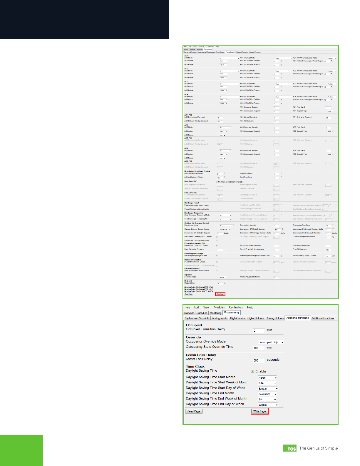
Configuration
Using Insight
TCS Insight software allows you to congure available settings for the different types of inputs and outputs of the
US5182. Each time you launch Insight, you must complete the following tasks before programming the US5182:
• Identify the COM port you will be using to communicate with the US5182
• Assign a unique device address to the US5182 (if more than one controller is connected to your system)
• Populate the I/O tabs under the Programming menu
NOTE: TCS Insight software is a powerful service tool that works with a number of different devices and performs other
functions which are beyond the scope of this manual. We recommend following only the steps described herein, as other
steps may impact other controllers or your network.
Network Setup
STEP 1 With the US5182 disconnected from your laptop,
launch Insight. You will see the following screen:
You may see no COM ports or several of them
(e.g., COM3, in this example). You can ignore
these ports.
STEP 2 Power up the US5182 (refer to the US5182
Installation Manual for more information).
STEP 3 Connect the US5182 to your laptop using the USB
cable described on page 3.
STEP 4 Click on the Get Ports button. You will see
a new COM port appear in the window (e.g.,
COM83). This is the port your US5182 is using to
communicate with the laptop.
STEP 5 Under the Baud Rate list, select UbiquiSTAT USB.
STEP 6 Open the new COM port by clicking on its radio
button.
STEP 7 Click on the Poll tab near the top of the window.