TdA DC535Y User manual

AUTOMATIC BOOM GATE
USER’S MANUAL
MODEL
DC535Y/DCZ535Y
DC655Y/DCZ655Y
WARNING!
ONLY QUALIFIED AND EXPERIENCED TECHNICIANS
SHOULD ATTEMPT INSTALLATION OR SERVICE TO THIS
UNIT, OTHERWISE, SERIOUS PERSONAL INJURY,
DEATH, OR PROPERTY DAMAGE MAY OCCUR.
PLEASE KEEP THESE INSTRUCTIONS FOR FURTHER
REFERENCE.
Total Door Automation (Australia) Pty Ltd
www.totaldoorautomation.com.au
sales@totaldoorautomation.com.au

DC535Y/DCZ535Y, DC655Y/DCZ655Y BOOM GATE USER’S MANUAL
2
OUTLINE
1. Important safety information……………………3
2. Introduction………………………………………3
3. Main technical parameters ……………………3
4. Installation ………………………………………4
5. Electrical…………………………………………9
6. Maintenance ……………………………………13
7. Troubleshooting…………………………………13
8. Packing list………………………………………14

DC535Y/DCZ535Y, DC655Y/DCZ655Y BOOM GATE USER’S MANUAL
3
1. Important safety information
Carefully read and follow all safety precaution and warnings before attempting to install and use
DC660-3(L, M, R) boom gate. Incorrect installation can lead to severe injury.
⚫The automatic boom gate should be installed by a qualified technician; otherwise, serious personal
injury or property damage may occur.
⚫Children should not be allowed to play near or operate automatic boom gate.
⚫Before any job on the boom gate, cut out electrical power.
⚫Do not in any way modify the components of the automatic boom gate, otherwise serious personal
injury or property damage may occur. We do not accept responsibility for damage or injury
resulting from installing this boom gate.
⚫Notify the users that the boom gate is never to be operated unless it is in full view.
⚫Always keep people and objects away from the boom gate when it is operated.
⚫Keep remote controls away from children, to prevent the boom gate from being activated
involuntarily.
⚫The distance between the end of the bar and the nearest objects should exceed 0.5m.
⚫Any changing of the bar by customer is not allowed. If you have any special requirements about
the bar, please kindly contact a dealer.
⚫Under no condition should boom gate be used with bar or spring not attached.
⚫For your safety, withdraw the crank before switching the power back on.
⚫For service, call an experienced technician.
⚫Our company reserves the right to change the design and specification without prior notification.
2. Introduction
Please read the instructions carefully before proceeding. The automatic boom gate intended for use in
parking area, commercial premises or apartment block access.
⚫Compact design, attractive appearance, safe and reliable performance.
⚫Self-locking at any position.
⚫A unique internal spring counterbalance mechanism aids the action of the boom gate.
⚫To ensure safety, the boom gate will reverse if it comes in contact with people or vehicle when
closing, and will stop if jammed when opening.
⚫Manual operation in case of power failure.
⚫Terminals available to photocell, loop detector and alarm lamp.
3. Main technical parameters
Type
DC535Y/DCZ535Y
DC655Y/DCZ655Y
Opening time
3.5 seconds
5.5 seconds
Bar length
3m~5m (standard)
5m~6m (standard)
Power supply
Single-phase AC240V 50Hz
Motor speed
1400r/min
Motor output power
180W
Duty cycle
40%
Noise
≤62dB
Measurement
360mm (L) x 230mm (W) x 1050mm (H)
Environmental temperature
-20ºC~+50ºC

DC535Y/DCZ535Y, DC655Y/DCZ655Y BOOM GATE USER’S MANUAL
4
4. Installation
Necessary Tools
The following tools may be necessary to install the automatic boom gate. You will need standard
screwdrivers, an electric drill and spanners.
The entire configuration and dimension are shown in the diagram below.
Fig.1
Top view
DC535Y/DCZ535Y, DC655Y/DCZ655Y BOOM GATE USER’S MANUAL
5
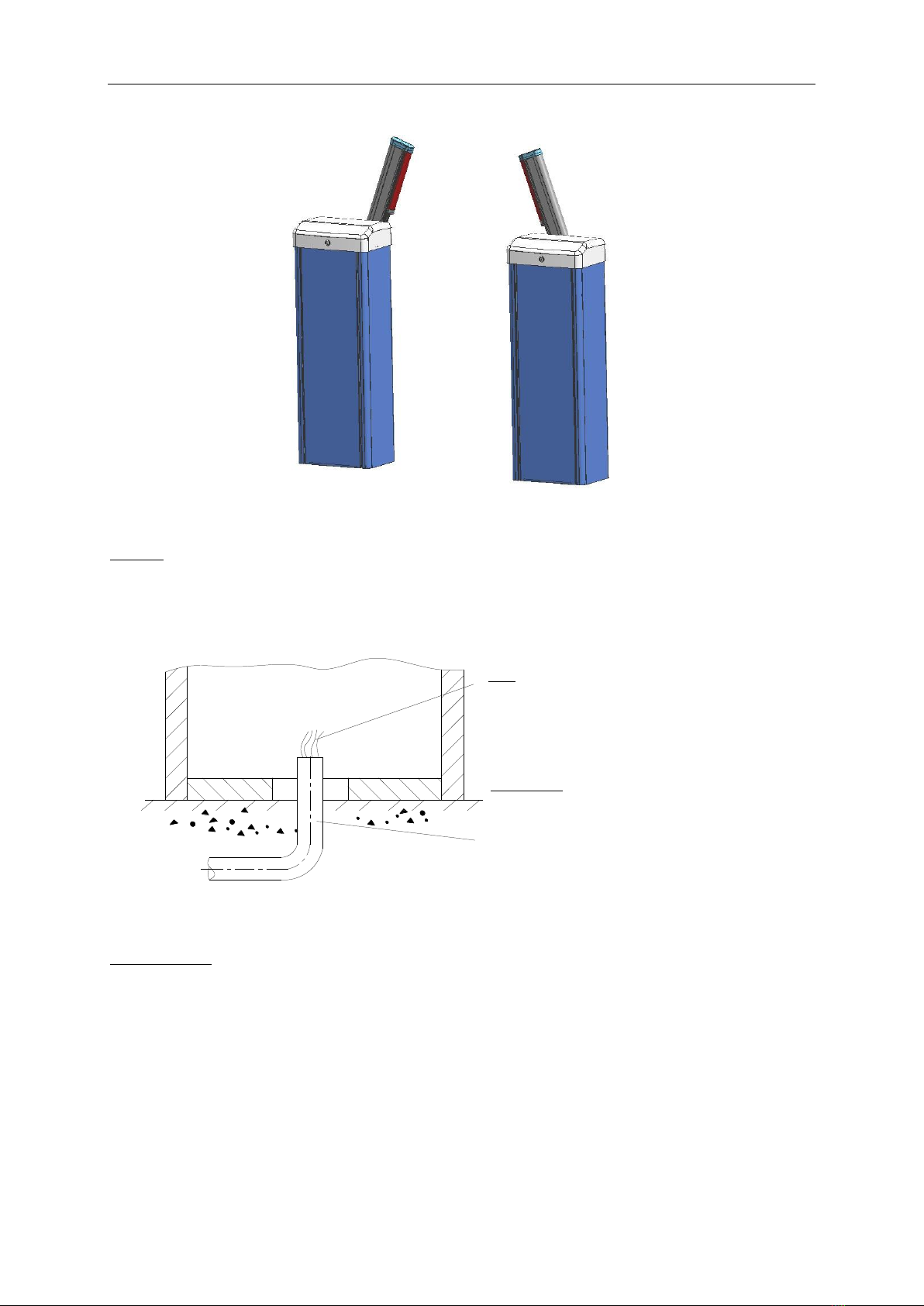
Right-hand boom gate (DC535Y, DC655Y) and left-hand boom gate (DCZ535Y, DCZ655Y)
DC535Y, DC655Y DCZ535Y, DCZ655Y
Fig.2
Conduit
Make one input hole for electric wires. In order to protect the wires, conduits must be set into the
concrete when it is poured. Wires within the conduit shall be located or protected so that no damage
can result from contact with any rough or sharp part.
2
PVC conduit (the conduit size should be more than
12mm in diameter)
We advise you to use two conduits: one for main
power wires, another one for control wires.
Always separate power wires from control wires.
Wire
The power wire size should be
more than 1.5mm .
The control wire size should be
more than 0.5mm .
2
Fig.3
Expansion bolt (see Fig.4)
⚫The boom gate requires a concrete pad in order to maintain proper stability. Place the boom gate
on its concrete pad and check the boom gate orientation with regard to the roadway.
⚫Mark the base hole locations onto the cement with a pencil or similar.
⚫Then move the operator to the side and drill the 4 holes on the marks that you have just drawn on
the concrete pad.
⚫Insert the (4) M12 wedge expansion bolts that are provided with the boom gate into the holes or
you can use the (4) M12 bolts, these bolts must be set into the concrete when it is poured.

DC535Y/DCZ535Y, DC655Y/DCZ655Y BOOM GATE USER’S MANUAL
6
Fig.4
Boom gate (see Fig.5)
Place the boom gate back into position, mount the boom gate to the concrete pad with washers and
nuts.
Fig.5
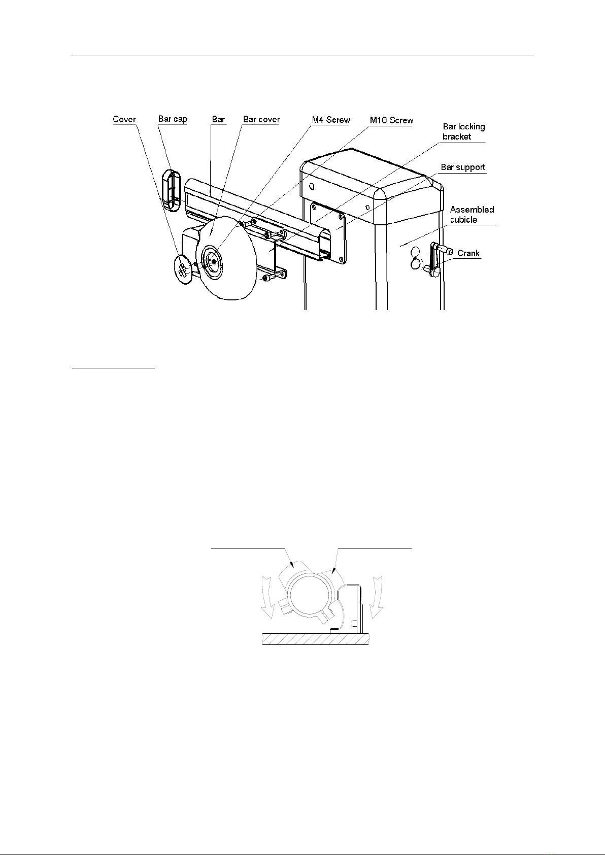
Bar (see Fig.6)
Mount the bar to the assembled cubicle and lock it with the four M10×16 socket head screws.
Mount the bar cover using the three M4×5 screws.
Manual operation (see Fig.6)
In case of power failure use crank to open or close boom gate manually, use the crank as follow:
⚫Shut off the main power of the boom gate. This safety measure is mandatory to avoid any risk of
injury in case of accidental running of the motor.
⚫Insert the crank in the opening of the housing (protected by a cover).
DC535Y/DCZ535Y, DC655Y/DCZ655Y BOOM GATE USER’S MANUAL
7
⚫Turn the crank clockwise or counterclockwise.
⚫Withdraw the crank before switching the power back on.
Fig.6
Limit switch (N.O.) see Fig.7
⚫The adjustable limit switches are used to stop the bar in the opened and closed positions.
⚫Loose the M4 screw of open limit cam, turn the open limit cam until the open limit switch light
illuminated, then tighten the screws.
⚫Loose the M4 screw of close limit cam, turn the close limit cam until the close limit switch
illuminated, then tighten the screws.
⚫After adjusting, you can open the bar then close the bar and observe whether the bar has
successfully reached the opened (vertical) position and closed (horizontal) position. If the bar does
not reach the opened position and closed position, you can repeat the adjusting process.
Close limit cam
Open limit cam
Fig.7
DC535Y/DCZ535Y, DC655Y/DCZ655Y BOOM GATE USER’S MANUAL
8
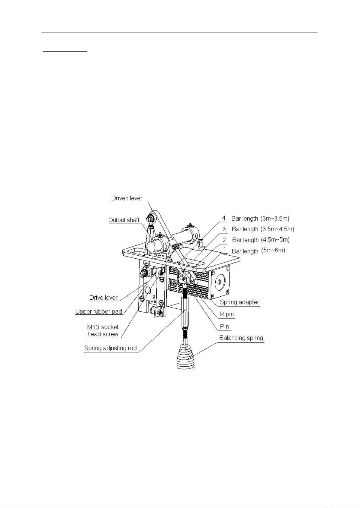
Balancing spring (see Fig.8)
Correct balancing is essential if boom gate is going to work properly. Rectify balancing spring only
when the bar is in open position (i.e. the balancing spring is loose).
Four holes (ø15) on the driven lever. The boom gate is normally delivered in the first hole
(DC655Y/DCZ655Y: suitable for bar length from 5m~6m) or the second hole (DC535Y/DCZ535Y:
suitable for bar length from 4.5m~5m). If you need to change it to the third (3.5m~4.5m) or the fourth
(3m~3.5m) hole proceed as follows:
⚫When the balancing spring is loose (the bar is in open position), undo the nuts, release the
balancing spring by turning the spring adjusting rod clockwise.
⚫Connect the spring adapter to the third or the fourth hole of driven lever, tighten with pin and R pin.
⚫Connect the spring adjusting rod to the balancing spring and spring adapter by turning spring
adjusting rod anti-clockwise. Tighten the spring adjusting rod to make the balancing spring for
ideal condition of use.
⚫Fasten the two nuts.
Fig.8
DC535Y/DCZ535Y, DC655Y/DCZ655Y BOOM GATE USER’S MANUAL
9
5. Electrical
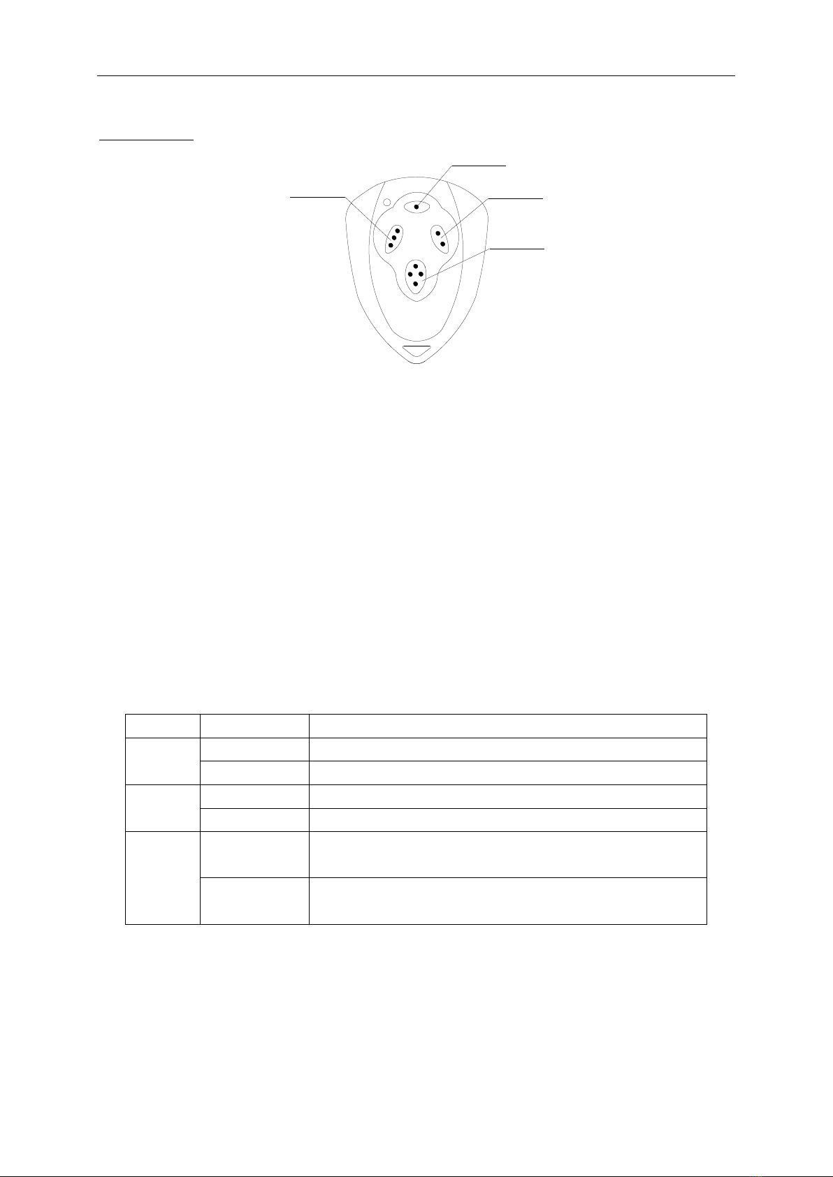
Remote control
Button 1
Button 2
Button 4
Button 3
Fig.9
⚫To add extra remote controls (Learning): Press the button ‘AN’(see Fig.10 control board
scheme No.13) on the control board, a beeper will be heard, then press the remote control button
which you want to use, the beeper will ring again, press the same remote control button again, the
beeper will ring at 1/2Hz frequency and then stop, the last ring is continuous. Then the learning
process is finished.
Up to 25 remote controls may be used.
⚫Erase remote controls: To erase all existing remote controls, press and hold ‘AN’ button, the
beeper will ring, release the button once the beeper stops ringing. This indicates that all the
remote controls have been erased completely.
⚫The remote control works in a single channel mode. With each press of the remote control button
the bar will open, stop, close or stop cycle.
DIP-switch (SW)
Position
DIP-switch
Function
1
ON
Limit switch mode is NC.
OFF
Limit switch mode is NO.
2
ON
Auto-close function is available.
OFF
Auto-close function is shut off.
3
ON
Programming / In this position the control board is in
programming condition, NOT USE condition.
OFF
Normal / In this position the control board can be normally
used.
⚫Set the bar auto-close function: (This feature can be selected to keep the bar stay open for
some seconds before it automatically closes. The auto-close time can be adjusted to between 0
and 44 seconds.) Please turn on the second and the third DIP-switch (see Fig.10 control board
scheme No.5 ‘SW’) to ON position. Press the remote control button which has been programmed
to open the bar, with the bar in vertical position, wait a few seconds according to your requirement

DC535Y/DCZ535Y, DC655Y/DCZ655Y BOOM GATE USER’S MANUAL
10
(the range is 0~44 sec.), this period of time is regarded as ‘auto-close time’. close the bar by
pressing the same button, after the bar stops at the horizontal position, return DIP-switch 3 to OFF
position. Thus the auto-close function has been set.
⚫Cancel auto-close function: Please turn on the second and the third DIP-switch (see Fig.10
control board scheme No.5) to ON position. Press the remote control button to open the bar. When
the bar stops at the vertical position, wait until the bar close automatically (45 sec.). After the bar
stops at the horizontal position, return DIP-switch 3 to OFF position immediately. Thus the
auto-close function has been canceled.
Note:
(1) If any button 1, 2, 3 has been set with auto-close function, then the other two buttons also have
this function. Button 4 needs to be set independently.
(2) There are two different ways to cancel the auto-close function:(a) see Cancel the auto-close
function section. (b) You also can turn off the second and the third DIP-switch to OFF position, the
auto-close function will be shut off. The auto-close feature will not function.
Activities covered in this section
Tuning the auto-reverse safety function
⚫Rotate the ‘Force Adj. VR1’knob (see Fig.10 control board scheme No.14) with a screwdriver. The
resistance may be increased or decreased by rotating clockwise or counterclockwise.
⚫If the boom gate operates freely and can auto-reverse in the event of an obstruction during closing
and stop in the event of an obstruction during opening, then the adjustment is completed.
Loop detector
⚫If loop detector detects vehicles during the bar closing, the bar will reopen immediately and stay
open until the vehicles move out of the loop, after vehicles move out of the loop, the bar will
continue to close.
⚫If loop detector detects vehicles when the bar stops at vertical or middle position, the bar will
remain stop until vehicles move out of the loop. After vehicles move out of the loop, the bar will
close.
If loop detector detects vehicles when the bar stops at horizontal position, the bar will not move.
⚫The bar will keep opening if loop detector detects vehicles during opening. After vehicles pass
through the loop, the bar will close.
Infrared photocell
⚫If infrared beam is interrupted during closing, the bar will reopen immediately.
Limit switch
⚫The switch is used to accurately stop the bar in the vertical and horizontal positions.
⚫If the bar stops at opened position (vertical) when the switch is reached, the bar will not move if
you press ‘▲’(Open) button of button switch.
⚫If the bar stops at closed position (horizontal) when the switch is reached, the bar will not move if
you press ‘▼’(Close) button of button switch.
Open priority
⚫The bar will return to open if press ‘▲’(Open) button of external button switch during closing.

DC535Y/DCZ535Y, DC655Y/DCZ655Y BOOM GATE USER’S MANUAL
11
Fig.10 control board scheme
DC535Y/DCZ535Y, DC655Y/DCZ655Y BOOM GATE USER’S MANUAL
12
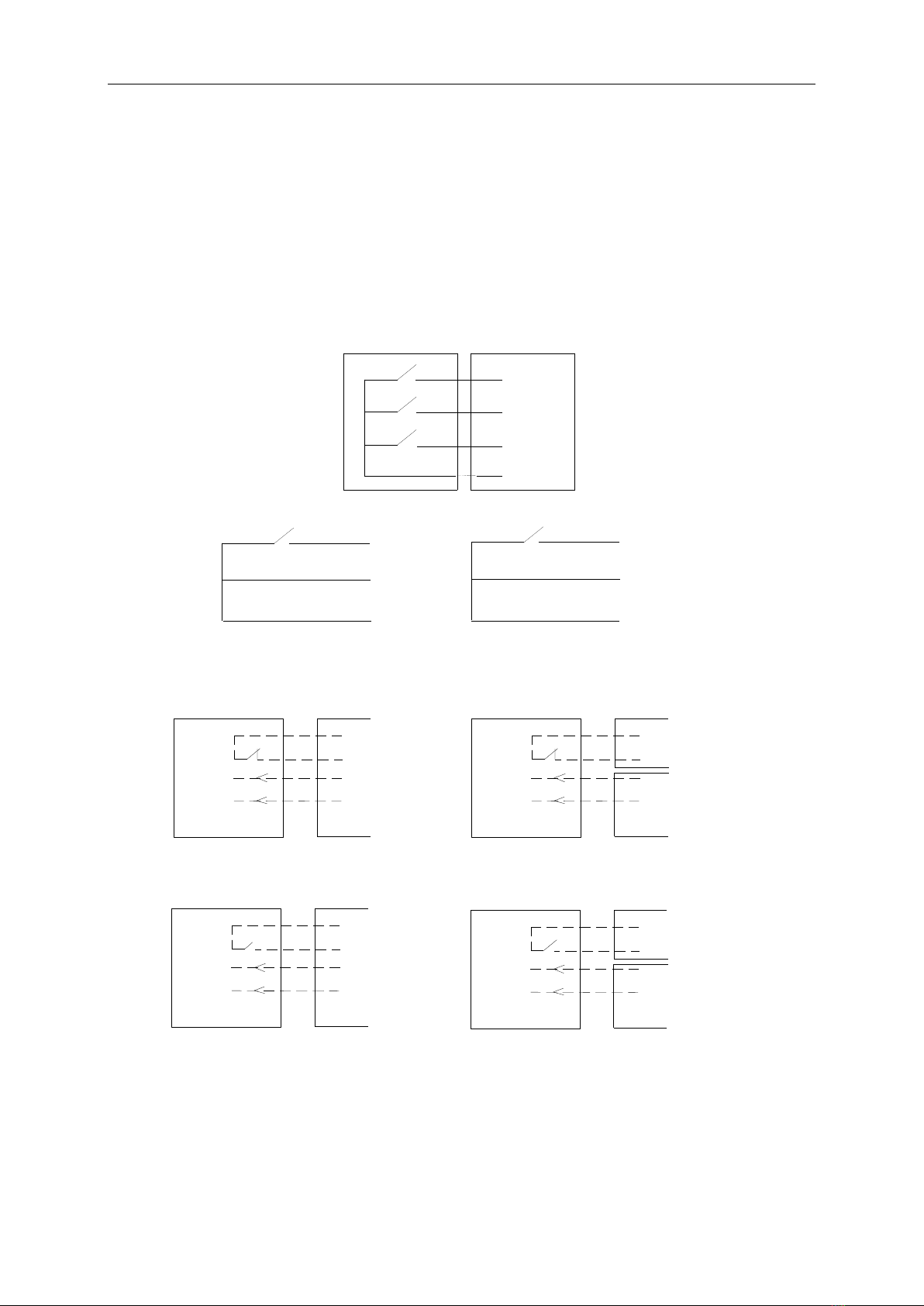
Wiring Notes of Control Board (See Fig.10)
1. Power Switch: ON/OFF
2. Fuse: 5A, Ø5x20
3. Antenna: ANT
4. Beeper: DC12V
5. DIP-switch
6. Memory Card: 93C66
7. MCU: PIC16C57C
8. External button Switch: T (Stop), G (Close), K (Open), COM (CO)
N.O.
COM
K
G
TControl box
Button switch
Common
Open
Close
Stop
9. Limit switch: CL(Close), COM (Com), OP (Open), +5V(DC +5V)
N.O.
COM
CL
OP
COM N.O.
+5V
+5V
Limit switch (close)
Limit switch (open)
10. Output power supply: +12V (DC +12V), COM (GND, CO),DET (Loop detector, normally open
contact), I.R. (Infrared, normally close contact)
COM
GND
+12V
Out COM
I.R
COM
+12V
Terminal
X8, No.10
Terminal
X8, No.10
I.R
COM
Out
COM
AC24V AC24V Terminal
X5,No.11
Infrared Control board Infrared Control board
Infrared with DC input Infrared with AC input
Loop detector with DC input
Control board
Loop detector
Terminal
X8, No.10
+12V
COM
DET
COM
Out
+12V
GND
COM
Loop detector with AC input
Control board
Loop detector
Terminal
X5,No.11
AC24VAC24V
COM Out COM
DET
Terminal
X8, No.10
11. Output Power Supply: AC24V
12. Power Indicator: LED
13. Learn Button (AN): LEARN
14. Force Adjustor: Clockwise +, Anticlockwise –

DC535Y/DCZ535Y, DC655Y/DCZ655Y BOOM GATE USER’S MANUAL
13
15. Transformer: 220V/12Vx2
16. Sampling Transformer: 110V/ 8.8V 4W
17. Alarm Lamp: AC220V
18. Motor Capacitor: 10μF 450V AC
19. Motor: U (Com), V (Positive direction), W (Opposite Direction), E (Earth)
20. Power Input: E (Earth), L (Live), N (Neutral) AC240V
6. Maintenance
⚫Every 3 months check and add grease (2#) regularly in two grease cups. There should be no
water and impurity in grease cup.
⚫Every 6 months check and add oil. Use WA220 oil only. To avoid high pressure in the reducer
casing, please loose the oil screw a little (one or two turns) before using.
Grease cup (2# grease)
Top view
Oil screw (WA220 oil inside)
Note: Loose the oil screw before
using to avoid oil leakage.
Fig.11
⚫Check and tighten the two M10 socket head screws in the driven lever.
⚫Check if all screws and nuts have been tightened firmly except oil screw as shown in Fig.11.
⚫Check if all wires are firmly connected to their respective terminal blocks.
⚫Make sure the bar is correctly fixed.
⚫Check the general state of the balancing spring.
⚫Keep boom gate clean at all times.
7. Troubleshooting
No.
Trouble
Possible causes
Solutions
1
The bar fails to close or
open fully.
Limit switch
Re-adjust the limit switch.
2
The bar opens too slowly.
Balancing spring
Adjust the balancing spring rod or
replace the balancing spring.
3
The indicator light on the
control box does not light.
Fuse blown
Replace fuse
4
The remote control
operating distance is too
short or not far enough.
Battery level may be
low.
Replace the battery inside of the
transmitter or try another transmitter.
5
Red indicator light of the
transmitter does not light.
Poor contacted.
Replace the transmitter.
DC535Y/DCZ535Y, DC655Y/DCZ655Y BOOM GATE USER’S MANUAL
14
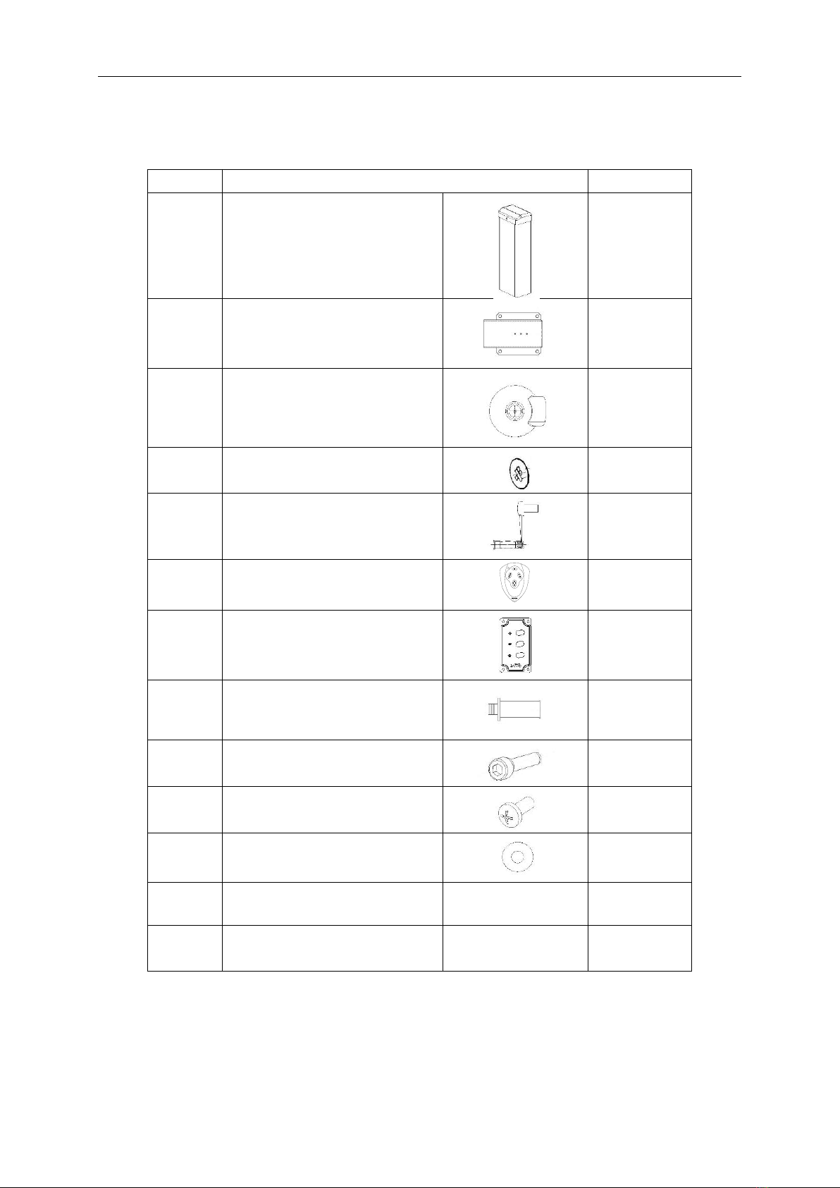
8. Packing list
Make sure that all parts are included before using. Refer to packing list. If any parts appear to be
missing, contact a dealer.
No.
Item
Quantity
1
Assembled cubicle
1
2
Bar locking bracket
1
3
Bar cover
1
4
Cover
1
5
Crank
1
6
Transmitter
2
7
Button switch(optional accessory)
1
8
Expansion bolt M12
4
9
M10×16 Screw for mounting bar
4
10
M4×5 Screw for mounting bar cover
3
11
Bigger washer
4
12
Key
2
13
User’manual
1
This manual suits for next models
3
Table of contents
Other TdA Gate Opener manuals


Popular Gate Opener manuals by other brands

DoorKing
DoorKing 9000 Series quick start guide

LOCKEY USA
LOCKEY USA TB200 installation instructions

Topens
Topens CASAR HJ4021 user manual

cedamatic
cedamatic RAM 50V Series Operating instructions and spare parts catalogue

DoorKing
DoorKing 6004 reference guide

GFA
GFA ELEKTROMAT KE 9.60 FU-25,00 installation instructions


Richmond
Richmond GTR062 user manual

Vimar
Vimar ELVOX RS20 Installation and operation manual

GFA
GFA ELEKTROMAT FT 80.5 FU-45,00 installation instructions

Maximum Controls
Maximum Controls MAX SUPER ARM 2300 manual

Cardin Elettronica
Cardin Elettronica 200/BL3924ESB instruction manual

Supeero
Supeero 606S Assembly instructions and directions for use