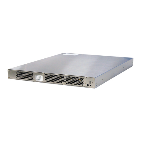
TDK-Lambda EZA2500 Series Original operating instructions

TENTATIVE
19-11-01
TDK-Lambda
EZA2500 series
Quick Manual /Basic
EZA2500-32048
Quick Manual
Basic version
BEFORE USING THE POWER SUPPLY UNIT (Common)
Be sure to read this instruction manual thoroughly before using this product. Pay attention to all cautions and
warnings before using this product. Incorrect usage could lead to an electrical shock, damage to the unit or a fire
hazard.
DANGER!
Never use this product in locations where flammable gas or ignitable substances are present.
INSTALLATION WARNING
• When installing, ensure that work is done in accordance with the instruction manual. When installation is improper, there is risk
of electric shock and fire.
• Installation shall be done by Service personnel with necessary and appropriate technical training and experience. There is a
risk of electric shock and fire.
• Do not cover the product with cloth or paper etc. Do not place anything flammable around. This might cause damage, electric
shock or fire..
WARNING on USE
• Do not touch this product or its internal components while circuit in operation, or shortly after shutdown. You may receive a
burn.
• While this product is operating, keep your hands and face away from it as you may be injured by an unexpected situation.
• There are cases where high voltage charge remains inside the product. Therefore, do not touch even if they are not in
operation as you might get injured due to high voltage and high temperature. You might also get electric shock or burn.
• Do not make unauthorized changes to this product nor remove the cover as you might get an electric shock or might damage
the product. We will not be held responsible after the product has been modified, changed or dis-assembled.
• Do not use this product under unusual condition such as emission of smoke or abnormal smell and sound etc. Please stop
using it immediately and shut off the product. It might lead to fire and electric shock. In such cases, please contact us. Do not
attempt repair by you, as it is dangerous for the user.
• Do not operate and store these products in environments where condensation occurs due to moisture and humidity. It might
lead fire and electric shock.
• Do not drop or apply shock to this product. It might cause failure. Do not operate these products mechanical stress is applied.
CAUTION on MOUNTING
• Confirm connections to input/output terminals are correct as indicated in the instruction manual before switching on.
• Input voltage, Output current, Output power, ambient temperature and ambient humidity should be kept within specifications,
otherwise the product will be damaged, or cause electric shock or fire.
• Do not use this product in special environment with strong electromagnetic field, corrosive gas or conductive substances and
direct sunlight, or places where product is exposed to water or rain.
• Mount this product properly in accordance with the instruction manual, mounting direction and shall be properly be ventilated.
• Please shut down the input when connecting input and output of the product.
• The power supply may cause damage when it intake conductive material, dust and liquid. When use this product, please be
careful to prevent entry of those materials to inside the product by using filter etc.
• Do not use this product in environments where causes the salt damage.
CAUTION on USE
• Product individual notes are shown in the instruction manual. If there is any difference with common notes individual notes
shall have priority.
• Before using this product, be sure to read the catalog and instruction manual. There is risk of electric shock or damage to the
product or fire due to improper use.
• Input voltage, Output current, Output power, ambient temperature and ambient humidity should be kept within specifications,
otherwise the product will be damaged, or cause electric shock or fire.

- 2 -
TDK-Lambda
EZA2500 series
Quick Manual / Basic
• If the built-in fuse is blown, do not use the product even after replacing the fuse as there is risk of abnormality inside. Be sure
to request repair to our company.
• For products without built-in protection circuit (element, fuse, etc.), insert fuse at the input to prevent smoke, fire during
abnormal operation. As for products with built-in protection circuit, depending on usage conditions, built-in protection circuit
might not work. It is recommended to provide separate proper protection circuit.
• For externally mounted fuse do not use other fuses aside from our specified and recommended fuse.
• This product was made for general purpose electronic equipment for standard industrial use and is not designed for
applications requiring high safety (such as extremely high reliability and safety requirements. Even though high reliability and
safety are not required, this product should not be used directly for applications that have serious risk for life and physical safety.
Take sufficient consideration in fail-safe design (such as providing protective circuit or protective device inside the system,
providing redundant circuit to ensure no instability when single device failure occurs).
• When used in environments with strong electromagnetic field, there is possibility of product damage due to malfunction.
• When used in environment with corrosive gas (hydrogen sulfide, sulfur dioxide, etc.) , there is possibility that they might
penetrate the product and lead to failure.
• When used in environments where there is conductive foreign matter or dust, there is possibility of product failure or
malfunction.
• Provide countermeasure for prevention of lightning surge voltage as there is risk of damage due to abnormal voltage.
• Connect together the frame ground terminal of the product and the ground terminal of the equipment for safety and noise
reduction. If these grounds are not connected together, there is risk of electric shock.
• Parts with lifetime specifications (built-in fan, electrolytic capacitor) are required to be replaced periodically. Set the overhaul
period depending on the environment of usage and perform maintenance. Also, note that there are cases when EOL products
cannot be overhauled.
• Take care not to apply external abnormal voltage to the output. Especially, applying reverse voltage or overvoltage more than
the rated voltage to the output might cause failure, electric shock or fire.
• Do not use in special environment such as places directly exposed to sunlight, dew condensation, moisture, rain, strong
electro-magnetic field, or corrosive gas (hydrogen sulfide, sulfur dioxide).
• This product has a built-in fan for air-cooling. Do not block the air intake and exhaust.
• The output of this product is considered to be a hazardous energy level (The voltage is 2V or more and the power is 240VA or
more). It must not be made accessible to users. Protection must be provided for Service Engineers against indirect contact with
the output terminals and/or to prevent tools being dropped across them. While working on this product, the DC input power must
be switched off and the input and output voltage should be zero.
• When short the output during operation, there is damage inside the converter.
• When change abrupt in Input voltage during operation, there is a Risk of damage inside the converter.
• When use the Electric storage device, Please refer to the manual of electric storage device and use the appropriate protection
device.
Note
• There is a possibility machining traces remain on sheet metal of product.
• Consider storage of the product at normal temperature and humidity avoiding direct exposure to sunlight at environment with
minimal temperature and humidity changes. Storage of product at high temperature, high humidity and environments with
severe changes in temperature and humidity might cause deterioration, and occurrence of condensation in the product.
• When disposing product, follow disposal laws of each municipality.
• Published EMI (CE, RE) or immunity is the result when measured in our standard measurement conditions and might not
satisfy specification when mounted and wired inside end-user equipment. Use the product after sufficiently evaluating at
actual end-user equipment.
• Catalogue, contents of the instruction manual may be changed without a prior notice. Refer to latest catalogue or instruction
manual.
• Reproduction or reprinting the instruction manual or its portion is forbidden without our permission.
- 3 -
TDK-Lambda
EZA2500 series
Quick Manual / Basic
Over view of Quick manual Basic version
In the Basic version of the Quick Manual, we will give a basic explanation of
EZA 2500.
In addition, we will explain the procedure of actually charging EZA by the
software “CNVCommCC” for operating from Windows PC by actually
connecting battery, inverter or 300-380 VDC AC-DC power supply.
“CNVCommCC” is distributed by TDK lambda.
Contents
1) Basic operation of EZA (boost, step-down)
2) EZA panel and terminal description
3) What to prepare before using EZA
a) Create an environment that can communicate with EZA
b) Connection with peripheral devices
4) Parameter setting and activation procedure of EZA
Try charging the battery in Manual CV mode of EZA
5) Confirm EZA startup
6) About occurrence of alarm
7) Reference material
Set value of parameter at factory shipment and upper / lower
limit value of parameter

- 4 -
TDK-Lambda
EZA2500 series
Quick Manual / Basic
1) Basic operation of EZA (boost, step-down)
In a typical DC-DC converter, the input terminal and the output terminal are determined, and
the voltage is converted from the input terminal side to the output terminal. On the other hand,
the EZA series is a power supply called bidirectional DC-DC converter which can arbitrarily
invert the relationship between input and output.
EZA also has a function to control output voltage and current (CVCC control * 1).
Specifically, the power conversion direction of “arrow ①” and the power conversion direction
of arrow ② in the above figure can be used by switching during the conversion operation.
There are roughly two ways to switch the direction of power conversion, and there are two
modes: a mode in which it switches over upon receiving an external command signal
(selectable by either RS485 communication or contact input) and the mode in which the voltage
set in EZA in advance, and EZA switches automatically.
Please refer to the practical skill section of the quick manual for the concrete method of
switching method.
* 1) CVCC control is to perform Constant Voltage operation and Constant Current operation so
as to achieve an arbitrary target voltage value and target current value. Constant voltage
operation is performed when the current value is less than the target current value, and constant
current operation is performed to lower the voltage so that it will not exceed the target current
value.
①
②

- 5 -
TDK-Lambda
EZA2500 series
Quick Manual / Basic
2) Explain of Terminal Connection and Panels
EZA 2500 terminals and Panels are shown in the figure below.
① LED of Indicator
The LEDs (3 pcs) indicates operating status of EZA2500.
② RESET :Tactile Switch
The tactile switch functions as alarm clear button when the alarm is activated due to abnormal
occurrence. When this switch is pushed, a command to clear the alarm is sent to the converter
while in alarm state (ALM LED ON). This switch does not function when converter is not alarm
state.
③ ADDRESS : Rotary Switch
The rotary switch functions as the RS-485 address setting for this converter. It is used to set
the lowest digits (last 4 bits) and DIP SW is used to set the highest digits.
← Light up at Discharge operating (Output from Low
Voltage to High voltage
)
← Light up at Charge operating (Output from High
voltage to Low voltage)
← Light up at Heavy Alarm
Resetting the control IC (CPU) on the control board can not be done
with this switch. It is necessary to set the applied voltage of both the
high voltage side and the low voltage side to 0 V and start the control
board again.
When controlling 14 or less EZAs with one interface of RS485, it is
recommended that DIP switches 6 to 8 are left unchanged from the
factory and specified by this switch.

- 6 -
TDK-Lambda
EZA2500 series
Quick Manual / Basic
④ Grid Connection Terminal (DC320V HVDC, Grand Terminal)
DC320V HVDC Power Supply Input Output Terminal, -V, +V (The fuse is connected to +V)
Please note that if you mistakenly connect polarity of plus or minus, internal circuit of EZA will
be damaged.
⑤ CN : External Signal Connector
It is an external signal terminal. I / O are open collector compatible.
It is used to control startup and stop without using RS485. Use this terminal also when you
want to provide an external switch for emergency stop.
⑥DIP SW
DIP Switch functions as a setting switch to designate operating mode and RS485 parameter of
this converter. DIP switch is turned ON when the lever is pressed down. The setting of the DIP
switch is effective when the CPU on the control board once goes reset.
⑦ RS-485 : Serial Interface Connector
LAN cable can be used with the same shape as Ether-net used on RJ-45 PC LAN. However, it
is not compatible with LAN (Ether-net). Check the pin assignment of RS-485 in the instruction
manual.
⑧ Battery Connection Terminal (DC48V LVDC Terminal)
DC48V Power Supply Input Output Terminal -V,-V, +V, +V (The fuse is connected to +V)
Please note that if you mistakenly connect polarity of plus or minus, internal circuit of EZA will
be damaged.
When controlling EZA with RS485, you do not need to use CN in
particular. (For details, see p10, 11 of the instruction manual)
In order to reset the CPU, it is necessary to turn the power supply
of EZA high voltage side and low voltage side once to 0V. (For
details, see the instruction manual p
10
)
There are two connectors, but you can connect to either cable. When
using multiple EZAs, connect the free port to the other EZA
connector with a cable. Such a way of connecting the communication
lines is called a daisy chain. (For details, see the instruction manual
p1
3
)

- 7 -
TDK-Lambda
EZA2500 series
Quick Manual / Basic
3) Preparing to use EZA2500
a) Preparing to communicate with EZA2500
EZA is a digitally controlled power supply with a control board inside. Even if a voltage is
applied to the input terminal, it will not be output unless it is sent to the start command to
control board from the host controller (PLC or PC:personal computer). Therefore, the
following preparation is necessary.
① Start the auxiliary power supply of the EZA. In the case of EZA 2500, when a voltage of
24 V or more is applied to the low voltage side or, 260 V or more to the high voltage
side with a power supply with a capacity of about 30 W or more, the auxiliary power
supply of the EZA is activated and the control board is activated. When the control
board starts up, RS485 for communicating with the outside becomes effective.
② Connect the host controller (PLC, PC) and EZA with RS485. For details of EZA's
RS485 communication specification, refer to p4 of EZA 2500 communication manual
which is separately distributed. The following points are listed below.
Item Specification Note
EZA side
connector
RJ45 It is the same shape as Ether-net of PC. Please
check the arrangement of pins with
communication manual p2.
Communication
System
half-duplex It consists of three lines of D +, D-, Grand
(Common), sometimes called 2 wire type. Please
be careful as it is different from our GENESYS
such as full duplex.
Transmission
character
specification
Data length 8 bits,
no parity, start 1 bit,
stop 1 bit
Can not be changed. Please adjust it on the host
controller.
Baud rate 9600-57.6kbps It is possible to set by Dip switch. Factory setting
is 19.2 kbps.
When connecting to a PC, you need an adapter to convert USB to RS485. Below, we will
introduce the adapters that our company is checking its operation.
・SYSTEM SACOM Industry Corp. USB-485I RJ45-T4P
SYSTEM SACOM Industry Corp. http://www.sacom.co.jp/index.html
Note) In this model, since the grand (Common)
terminal of the RJ45 is pin 7, please connect the 8
pin and 7 pin of the internal board with the jumper
wire and the pin 8 to be the grand (Common)
terminal.

- 8 -
TDK-Lambda
EZA2500 series
Quick Manual / Basic
・Hjelmslund Electronics USB485-MB45
Hjelmslund Electronics http://www.hjelmslund.dk/default.asp
When using above, it is necessary to install the exclusive driver software distributed by the
manufacturer on your personal computer. For details, refer to the instruction manual of the
maker purchased.
b) Connection with peripheral devices
The following figure shows an example of connection when EZA 2500 is controlled from a PC:
personal computer using RS-485.
In the figure, the inverter is supposed to be capable of bidirectional power conversion from AC
to DC, from DC to AC, called a regenerative function, and supplies electric power converted
from AC to DC to EZA during battery charging.
Note) Since there is a male terminal of RJ45, you
can connect it to RJ45 of EZA and use as it is.
Considering CPU reset, maintenance, and troubleshooting, it is
recommended to insert NFB and magnet switch between the
battery and EZA, EZA and inverter respectively.
When the auxiliary power supply of EZA is activated, the
communication with EZA is possible with RS485 and the internal
parameter setting becomes possible.

- 9 -
TDK-Lambda
EZA2500 series
Quick Manual / Basic
Regarding battery charging performed on the following pages, it is also possible to use a
constant voltage power supply (eg GENESYS series of TDK lambda) that can output 300-380
VDC instead of DC / AC inverter. However, when the EZA is discharged, the constant voltage
power supply may be damaged, so be sure to place a diode with a capacitance of 10A or more
and a withstand voltage of 450V or more between the constant voltage power supply and the
EZA.

- 10 -
TDK-Lambda
EZA2500 series
Quick Manual / Basic
4) Parameter setting and startup procedure of EZA
This section explains the procedure to activate EZA2500 and charge the battery by the EZA
communication software "CNVCommCC" with RS485 communication. Assume that each
parameter (set value) such as voltage and current of the EZA 2500 is left unchanged from the
factory (see p. 22, 23 in this manual).
②
Set EZA2500 to operate via RS
-
485.
① Install "CNVCommCC" on Windows PC where USB / RS485
converter driver is installed
EZA does not have volume for output adjustment. Output voltage,
current etc. are all set by setting parameters via RS485.
Install "CNVCommCC" according to the operation manual distributed with it.
Set EZA 2500 to operate via RS - 485 and address on RS - 485 to "0" and set the
communication speed to 19.2 kbps.
Set the rotary switch to 0 on the front panel as shown in the picture below.
※ The factory setting is the above setting.
After setting the terminal voltage on both the grid side and battery
side of the EZA to 0V. Set all to OFF (push up) as shown in the photo
below the DIP switch on the back side.
※ The factory setting is the above setting.

- 11 -
TDK-Lambda
EZA2500 series
Quick Manual / Basic
④
Confirm that you can communicate with PC with EZA.
③
Restart the control board.
Apply specified voltages to the grid side and battery side terminals of the
EZA. This operation is unnecessary if you do not operate the DIP switch
or rotary switch
The control board is activated by applying the
specified lower limit voltage to either the battery
side or the grid side.
When the control board is activated, the green
LED that is visible through the punching metal on
the back panel, lights up.
Confirm that you are connected as shown in p8 or p9 of this manual.
Launch “CNVCommCC.exe” on your computer.
※The following message is displayed at the initial startup or when the
port you used last time cannot be opened.
Please click "OK" and make communication settings.
If you select "Communication Setting" from the menu, or if you cannot open the
port at startup, the communication setting window will be displayed.
Follow the
instructions on the next page to configure communication settings.
Communication setting
The control board reads the values of DIP switch
and rotary switch at restart.

- 12 -
TDK-Lambda
EZA2500 series
Quick Manual / Basic
① Port Number Selection: Select the port number in the box.
· The COM port list of the PC is displayed in this box.
· If the COM port is not displayed, check the COM port of PC and restart
“CNVCommCC”.
② Baud rate selection box: Select 19200.
③Press the "SET" button.
CNVCommCC applies the settings and opens the port.
④ If opening the port fails, an error message is displayed. Click the
“CLOSE” button to close the window. Check the COM port and the EZA
DIP switch settings, and start over from step ①.
Communication setting
window
If the COM port is not displayed, there is a possibility that
the USB / RS 485 conversion converter is not functioning
properly. Confirm that the driver distributed by the
conversion converter manufacturer is correctly installed on
the PC.
EZA's DIP switch is set at 19200 baud rate at factory
shipment.

- 13 -
TDK-Lambda
EZA2500 series
Quick Manual / Basic
Address setting
You can set the EZA address and PC address to communicate on the main screen's
address setting panel. Please select the EZA address and PC address you want to
communicate with.
① Set the address of the EZA you want to communicate with in communication with
EZA.
· Turn ON the single target radio button. (We will perform 1: 1 communication with
EZA.)
· Specify "0 (0x00)" for the EZA address.
② Set "126 (0x7E)" as the address of Own Address (Your personal computer).
②
①

- 14 -
TDK-Lambda
EZA2500 series
Quick Manual / Basic
Confirm communication
Make sure you can communicate with EZA.
① Click on the "Main" tab in a state where it can communicate with EZA and display
the main screen.
② Click on the "READ" switch of “ [10] Converter Meter1” in the lower left.
③ Verify that the values of the sensor for each voltage, current, power, internal
temperature of EZA are displayed on the screen.
When communication with the EZA fails, "Timeout" is
displayed in “Communication status” at the upper right of
the screen.
If the communication fails, please confirm the procedure up
to this point according to this manual again. If it still fails,
please contact our person in charge.
Sensor values include errors. Please check the maximum
error value in the reading accuracy item of the specification
sheet.
①
②
③

- 15 -
TDK-Lambda
EZA2500 series
Quick Manual / Basic
Calibration
Calibrate “CNVCommCC”.
①Select "Tools → CNVCommCC calibration" of the menu bar in a state where it can
communicate with EZA.
②Calibration is done automatically.
Calibration information is automatically acquired from EZA. Once
calibration is performed, information is written to the “CNVCommCC”
configuration file, so it is not necessary to perform calibration from
the next startup.

- 16 -
TDK-Lambda
EZA2500 series
Quick Manual / Basic
①
②
③
④
⑤
①
We will set up the parameters in the Manual CV mode.
Notes) The following settings differ depending on the battery used. Make sure to
check with the battery manufacturer.
●Setting the battery charge voltage and protection
①Click the "Other Setting" tab in a state where it can communicate with EZA. And
click "READ ALL" to read the current parameters of EZA.
②Write the following parameters to the area surrounded by the red line in the above
figure.
Target Battery Voltage → "50" (V)
Limit of Battery Voltage for Discharging→ "40" (V)
③Turn on the radio buttons of "Battery Over Charging Protection" and "Battery Under
Discharging Protection", respectively, surrounded by the red line in the above figure.
④.Click the ”WRITE”
⑤Click the ”READ” to display the current value and confirm that the value has been
written.
※The EZA controls the charging current to be 0A at 50V to prevent overcharging of
the battery, and controls the discharging current to be 0A at 40V to prevent the over
discharging.
⑤
Set parameters of EZA.

- 17 -
TDK-Lambda
EZA2500 series
Quick Manual / Basic
①
②
④
⑤
①
③
●Set battery charge current
①Click on “Other Setting” tab in a state where it can communicate with EZA. And
click "READ ALL" to read the current parameters of EZA.
② Write " 1 ” (A) in " Current Limit of Battery" of the area surrounded by the red line
in "[06]Converter Protection Parameter".
③Write "38"(V) in "Under Battery Volts" and "52V"(V) in "Over Battery Volts".
④Click the ”WRITE”.
⑤Click the ”READ” to display the current value and confirm that the value has been
written.
※ The charge current (Current Limit of Battery) of the battery is now set to 1A. And
when the battery reaches the target voltage, the EZA controls the charge current to
0A. In the unlikely event that the battery voltage drops below 38V or above 52V, EZA
will stop and issue an alarm to protect the battery.
The operation up to here (up to parameter setting) is possible without connecting
anything to the high voltage side of EZA if you connect a battery or DC 24 to 60 V
power supply to the low pressure side.
The Limit of Battery Voltage for Discharge and Battery Under Discharging Protection
settings are not required for charging, but when discharging, be sure to set the
optimal Limit of Battery Voltage for Discharge for yo
ur battery to protect the battery.

- 18 -
TDK-Lambda
EZA2500 series
Quick Manual / Basic
①
②
③
④
Charge the 48V battery in Manual CV mode up to 50 V with the charging current 1A.
●Make sure that the power supply, a voltage of 300 V - 380 V and a power of 1A or
more, are connected to the high voltage side of EZA.
●On the main screen, start up as follows.
①Click on the "Main" tab in a state where it can communicate with EZA.
②Turn on the radio buttons of "Other driving" and "Battery CC", respectively,
surrounded by the red line in the above figure.
③Click the “Battery CV”.
※EZA starts and the fan starts rotating. EZA charges the battery with charging
current 1 A until it reaches 50 V. When the battery voltage reaches 50 V, EZA
controls the charging current to 0 A.
④ By clicking "Stop", the main converter of EZA stops.
⑥
Start EZA and charge the battery.
When EZA 2500 starts, EZA 2500 self-consumes about 100 W at
maximum with main circuit and cooling fan. Here we use 50 V × 1 A =
50 W electric power for battery charging, so connect a power supply of
300 W or more with enough margin.

- 19 -
TDK-Lambda
EZA2500 series
Quick Manual / Basic
①
②
③
④
⑤
5) Confirm EZA startup
You can check that EZA is running as follows.
● The cooling fan rotates.
● The green "GEN" or "REG" LED on the front panel turns on.
● Check the EZA status via RS485.
The confirmation using “CNVCommCC” via RS485 is explained below.
① Click the “Main” tag in a state where it can communicate with EZA.
② "[02] Converter Status" Click the “READ” in Converter Status.
③ "Charging" is displayed in the square under "Running State".
④ Click the "READ" in "[10] Converter Meter1.
⑤ Battery voltage value etc. at the time of clicking the "READ", will be displayed in
the square beside it.
EZA will rotate the cooling fan for about 3 minutes to cool the interior
even after the main converter stops, then stop the fan.

- 20 -
TDK-Lambda
EZA2500 series
Quick Manual / Basic
④
③
②
①
6) About the Alarm of EZA
● EZA generates the Alarm signal and stops when a device error occurs. There are two
kinds of Alarms as follows.
a) Light alarm: EZA stops. If the cause of the EZA abnormality is removed, the
operation state is automatically restored. The alarm signal is not output.
b) Heavy alarm: EZA stops. Even if the cause of the EZA abnormality is removed, the
operation state will not return unless the return signal is input. In this case, the red
LED of "ALM" on the front panel will light, and “pin1” of the external signal
connector CN will be open. To restore, it is necessary to press the reset switch on
the front panel, or input the return signal by either of the methods of shorting the CN
“pin11” to the “SG” terminal and opening it, or sending the return signal via
RS485 .
● The following describes how to check the alarm and input the restoration signal by
using “CNVCommCC”.
For details of alarms, refer to p11, 12 and p14-16 of EZA2500series
Instruction manu
al.
Other manuals for EZA2500 Series
3
This manual suits for next models
3
Table of contents
Other TDK-Lambda Media Converter manuals

TDK-Lambda
TDK-Lambda EZA11K Series Installation guide

TDK-Lambda
TDK-Lambda Vega DC User manual

TDK-Lambda
TDK-Lambda EZA11K Series Installation guide

TDK-Lambda
TDK-Lambda CHVM1R5 Series User manual

TDK-Lambda
TDK-Lambda PYH200 Series User manual

TDK-Lambda
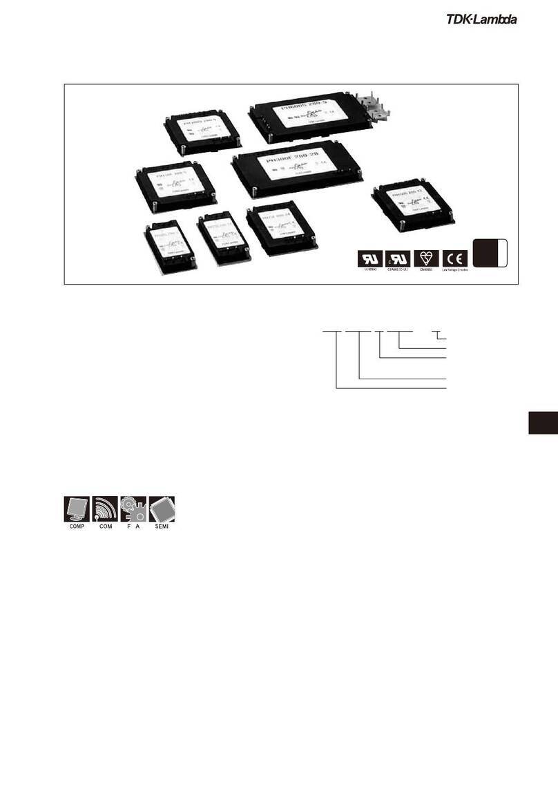
TDK-Lambda PH Series User manual

TDK-Lambda
TDK-Lambda CHVM2 Series User manual

TDK-Lambda
TDK-Lambda PFE500F Series User manual

TDK-Lambda
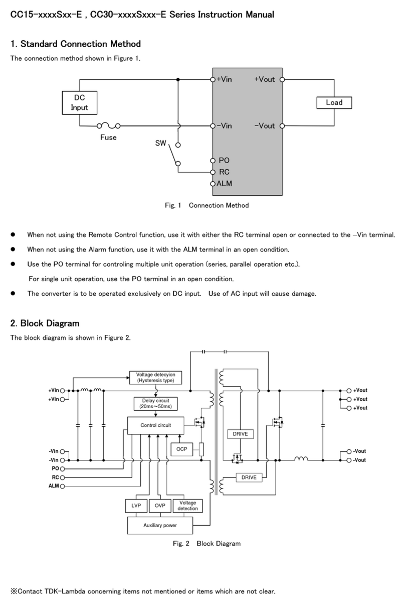
TDK-Lambda CC15-xxxx-Sxx-E Series User manual

TDK-Lambda
TDK-Lambda EZA 2500 - 32048 User manual