TDK-Lambda PYH200 Series User manual

PYH200 Manual
DC-DC Converter Isolated, 200W, ½ Brick, PCB Mount
PYH200 Series
Instruction and Application Manual
Content:
1. Product Description.............................................2
2. Product Features .................................................2
3. Intended Use .......................................................2
4. Installation Instructions ......................................3
5. Functional Description ........................................4
6. Functional Diagram.............................................5
7. Recommended Wiring Scheme...........................5
8. Product Nomenclature and List of Models ........6
9. Short-form Data ..................................................6
10. Efficiency and power dissipation curves ............8
11. Physical Dimensions and Pin Layout:..................9
12. Isolation and Dielectric Strength......................10
13. Protection Features ...........................................11
14. Approvals and Regulatory Compliances ..........12
15. Rail Applications................................................12
16. Thermal Consideration and Derating ..............13
17. EMC Considerations ..........................................14
18. Remote ON/OFF Function .................................16
19. Output Remote Sensing....................................16
20. Output Voltage Adjustment.............................17
21. Synchronizing the Switching Frequency ..........18
22. Hold-up Time Circuitry......................................18
23. Series Operation of Outputs.............................19
24. Parallel Operation of Outputs..........................19
25. Accessory - Heatsinks ........................................20
26. Cleaning Process and Soldering Profile............21
All parameters are typical values specified at nominal input voltage, nominal output load, 25°C ambient and after a 5 minutes run-in time unless
otherwise noted. The information presented in this document is believed to be accurate and reliable and may change without notice.
For additional information, please visit https://product.tdk.com/info/en/products/power/index.html 1/21
DOC-ID: IM-PYH200-2022-05-04

PYH200 Manual
DC-DC Converter Isolated, 200W, ½ Brick, PCB Mount
1. PRODUCT DESCRIPTION
The PYH200 series are board mount 200W DC-DC converters in a rugged half-brick housing with silicone
potting. They provide a regulated and galvanically isolated output voltage.
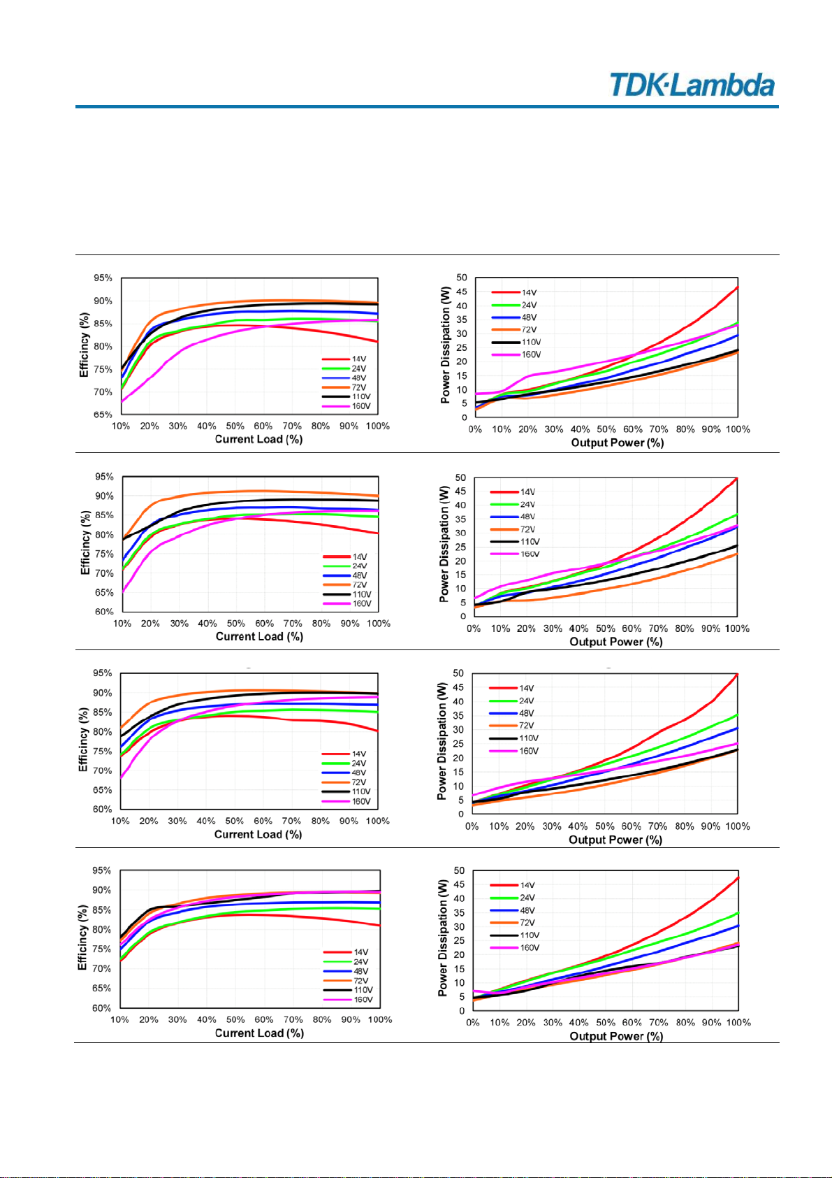
The most outstanding features of this series are the exceptionally wide input voltage range from 14V to 160V
(12:1) and the high input/output isolation strength of 3000Vac.
The wide allowed case temperature range from -40°C to +100°C, the low heat generation, due to the high
efficiencies up to 90% and the high shock and vibration resistance thanks to the potted design make this
device suitable for nearly every situation.
Another unique feature is the compliance with the standard EN 50155, which is an international standard
covering electronic equipment used on rolling stock for railway applications. In combination with the wide
input voltage range, there are many application opportunities in this segment. Further applications for this
DC-DC converter can be found in Distributed Power Architecture (DPA), telecommunications, battery-
powered devices, measurement and laboratory equipment, devices in industrial environments, and many
other areas.
2. PRODUCT FEATURES
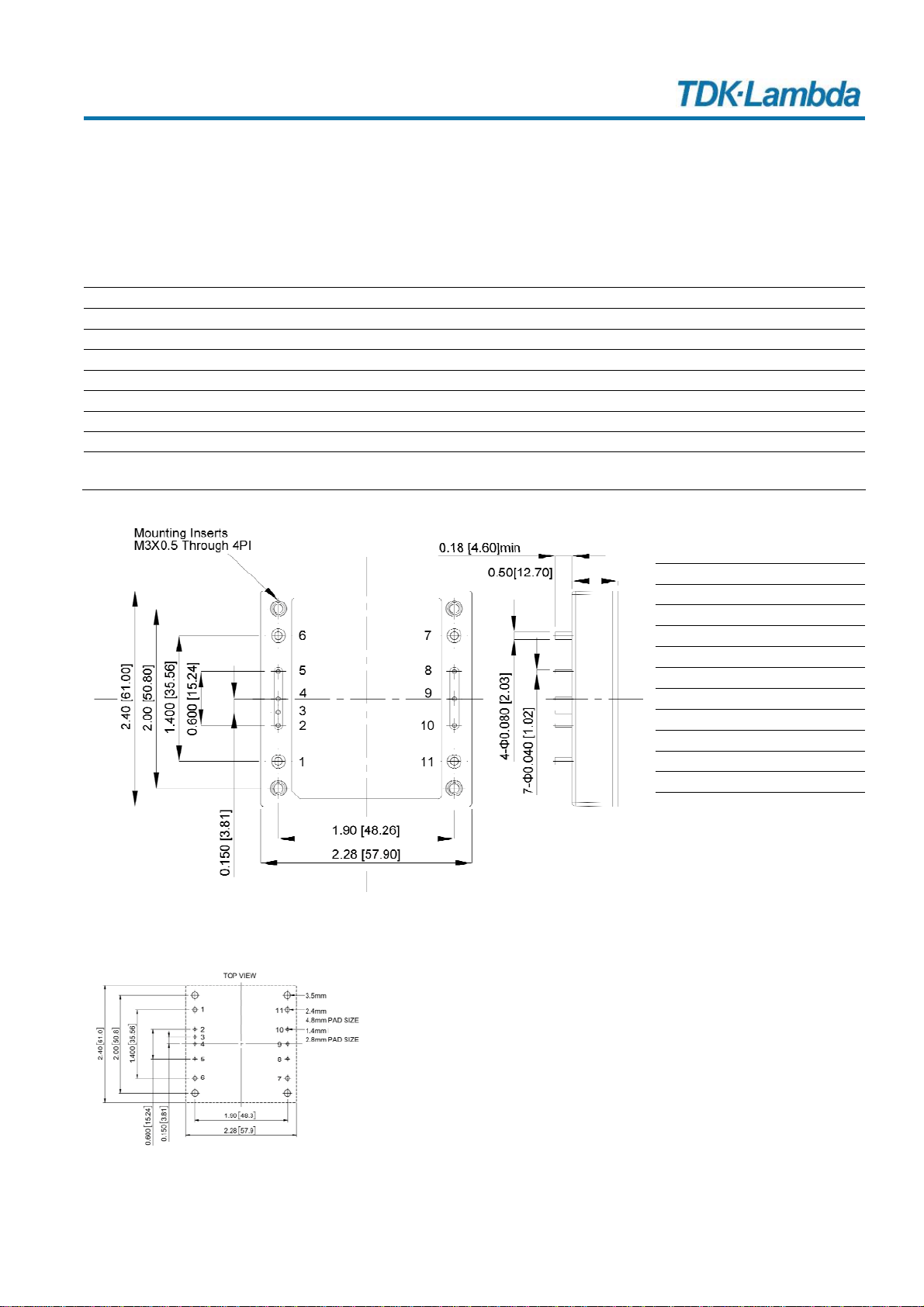
- Half-brick (2.28x2.4”) Industry Standard Footprint
- 3000Vac Input to Output Isolation
- 14-160V (12:1) Wide-range Input
- EN 50155 Railway Compliant
- IEC 62368-1 (ICT) Approved
- High Shock and Vibration Resistance Due to Potted Design
- Efficiency up to 90%
- -40 to +100°C Operating Case Temperature Range
- Remote ON/OFF Input
- Output Voltage Sense Lines
- Frequency Synchronization With External Clock
3. INTENDED USE
This device is designed and manufactured as a component part to be mounted on a pc-board and to be
installed in electronic devices.
This device is intended for commercial use, such as in industrial control, process control, monitoring and
measurement equipment or the like.
Additionally, this device is also designed for equipment that is intended for use in railway rolling stock
applications according to EN 50155.
Do not use this device in equipment, where malfunctioning may cause severe personal injury or threaten
human life without additional appropriate safety devices, that are suited for the end-application.
If this device is used in a manner outside of its specification, the protection provided by the device may be
impaired.
All parameters are typical values specified at nominal input voltage, nominal output load, 25°C ambient and after a 5 minutes run-in time unless
otherwise noted. The information presented in this document is believed to be accurate and reliable and may change without notice.
For additional information, please visit https://product.tdk.com/info/en/products/power/index.html 2/21
DOC-ID: IM-PYH200-2022-05-04

PYH200 Manual
DC-DC Converter Isolated, 200W, ½ Brick, PCB Mount
4. INSTALLATION INSTRUCTIONS
Before operating this device, please read this manual thoroughly and retain for future reference! This device
may only be installed and put into operation by qualified personnel. If damage or malfunction should occur
during operation, immediately turn power off and send device to the factory for inspection. The device does
not contain serviceable parts.
WARNING Risk of electrical shock, fire, personal injury or death.
Turn power off before working on the device. Protect against inadvertent re-powering.
Do not modify or repair the unit.
Do not open the unit as high voltages are present inside.
Use caution to prevent any foreign objects from entering the housing.
Do not use in locations where flammable gas or ignitable substances are present.
Do not use in wet locations or in areas where moisture or condensation can be expected.
Do not use in environment with strong electromagnetic field, corrosive gas or conductive substances or direct
sunlight.
Do not touch during power-on, and immediately after power-off. Hot surfaces may cause burns.
Obey the following installation instructions:
This device may only be installed and put into operation by qualified personnel.
This device does not contain serviceable parts. Replace fuses only when explicitly permitted. If damage or
malfunction should occur during installation or operation, immediately turn power off and send unit to the
factory for inspection.
Install the device in an enclosure providing protection against electrical, mechanical and fire hazards.
The device is designed for pollution degree 2 areas in controlled environments. No condensation or frost is
allowed.
The input can be powered from batteries or similar DC sources.
Check for correct input polarity. The device will get damaged when the voltage is reversed.
Ensure sufficient cooling to avoid overloading the device.
The device is designed for altitudes up to 5000m (16400ft).
This device is not internally fused. An external input fuse must always be used. Use a 25A slow-blow fuse.
The maximum operational case temperature is +100°C (+212°F). The case temperature is defined in the
middle of the top side of the cover.
The device is designed to operate in areas with a maximum relative humidity of 95%.
Do not apply return voltages from the load to the output terminals.
Do not connect the outputs of multiple devices in parallel for higher output currents.
Do not connect batteries for charging purposes to the output of the device.
All parameters are typical values specified at nominal input voltage, nominal output load, 25°C ambient and after a 5 minutes run-in time unless
otherwise noted. The information presented in this document is believed to be accurate and reliable and may change without notice.
For additional information, please visit https://product.tdk.com/info/en/products/power/index.html 3/21
DOC-ID: IM-PYH200-2022-05-04

PYH200 Manual
DC-DC Converter Isolated, 200W, ½ Brick, PCB Mount
5. FUNCTIONAL DESCRIPTION
The output is electronically protected against no-load, overload and short circuit. In case of an overload or
short circuit, the device will operate intermittently (hiccup mode).
The device can supply resistive and inductive loads.
Avoid loads with large input capacitances. If the capacitive load is higher than the values specified, the device
operates in an intermittent mode (hiccup mode).
PYH200-72WS12: max. 76700µF
PYH200-72WS15: max. 13500µF
PYH200-72WS24: max. 8000µF
PYH200-72WS48: max. 2200µF
The output voltage can be adjusted with an external resistor connected between the TRIM-pin and the output
voltage.
The device is equipped with sense lines for the output voltage. This feature moves the output voltage
regulation point from the output of the device to the point of connection of the remote sense pins.
The device is equipped with an over-temperature protection. In case of a high temperature, the output shuts
down and starts automatically after cooling off.
The device is equipped with under-voltage protection on the input side. If the input voltage is too low, the
device does not start or switches off. The turn-on and shut-down voltage can be adjusted externally.
In case of an internal defect, a redundant circuit prevents the output voltage from becoming excessive or
dangerous (zener diode type protection).
The device is equipped with a remote ON/OFF function.
The device has an access to the internal bus voltage, which can be used to add additional components for
extended hold-up time.
The device is equipped with a SYNC control pin for frequency synchronization with an external clock signal.
All parameters are typical values specified at nominal input voltage, nominal output load, 25°C ambient and after a 5 minutes run-in time unless
otherwise noted. The information presented in this document is believed to be accurate and reliable and may change without notice.
For additional information, please visit https://product.tdk.com/info/en/products/power/index.html 4/21
DOC-ID: IM-PYH200-2022-05-04

PYH200 Manual
DC-DC Converter Isolated, 200W, ½ Brick, PCB Mount
All parameters are typical values specified at nominal input voltage, nominal output load, 25°C ambient and after a 5 minutes run-in time unless
otherwise noted. The information presented in this document is believed to be accurate and reliable and may change without notice.
For additional information, please visit https://product.tdk.com/info/en/products/power/index.html 5/21
DOC-ID: IM-PYH200-2022-05-04
6. FUNCTIONAL DIAGRAM
Input
+
-
Output
Output
Voltage
Adjust
OVP: Overvoltage,
OCP: Overcurrent,
SCP: Short-circuit
Protection
Input
Filter
(Pi-type)
Remote
ON/OFF
Output
Filter
Power
Converter
Output
Voltage
Regulator
+
-
1
6
4
11
7
9
RC
(ON/OFF)
TRM
(Trim)
UVP:
Undervoltage
Protection
OTP: Over-
temperature
Protection
Sense
Line
Reg.
10
8
+Sen
-Sen
2
UVLO
Coverter
Control
5
BUS
3
SYNC
Functional diagram Pin assignment
RC: Remote ON/OFF control pin
TRM: Trim pin for output voltage adjustment
UVLO: Control pin for under-voltage lock-out behavior
BUS: Access to internal bus voltage, can be used for hold-up time purposes
SYNC: Control pin for frequency synchronization with external clock signal
-Sen, +Sen: Sense lines for output voltage
7. RECOMMENDED WIRING SCHEME
PYH
+Vout
-Vout
+Vin
-Vin
Load
TVS
FUSE EMI Filter
DC
Source
+
+
-
D1
F1
C1
+
C3
C2
BUS
C4
+
+Sen
-Sen
Fuse F1: The DC-DC converter is not internally fused. An external input fuse must always be used. Use a
25A slow-blow fuse.
Capacitor C1 and Diode D1: These two components provide higher transient resistance (surge and burst)
at the input and are required if the DC-DC converter has to meet the EN61000-4-4 and EN61000-4-5
standards. The capacitor C1 should be 100µF/200V and the suppressor diode D1 should be a SMCJ180A.
EMI Filter: This filter reduces the conducted emission to the input. A circuit example can be found in the
chapter "EMC Considerations".
Capacitor C2, C3: For a good transient response behavior, low ESR output capacitors should be utilized. Use
a 1µF ceramic multilayer capacitor for C2 and a 10µF aluminum or tantalum capacitor for C3.
Capacitor C4: External capacitor connected between BUS and -Vin is necessary to keep operating stable.
Use an aluminum capacitor with 240µF (e.g. VISHAY 118 AHT series)

PYH200 Manual
DC-DC Converter Isolated, 200W, ½ Brick, PCB Mount
All parameters are typical values specified at nominal input voltage, nominal output load, 25°C ambient and after a 5 minutes run-in time unless
otherwise noted. The information presented in this document is believed to be accurate and reliable and may change without notice.
For additional information, please visit https://product.tdk.com/info/en/products/power/index.html 6/21
DOC-ID: IM-PYH200-2022-05-04
8. PRODUCT NOMENCLATURE AND LIST OF MODELS
Product Nomenclature:
PY bb ccc eed z
Series Name
PY
Output Power
200 = 200W
Input Voltage
72W = 14-160V
Output Voltage
12 = 12V
15 = 15V
24 = 24V
48 = 48V
Output Type
S = Single Output
- -a
Size
H = Half Brick
Options
Remote ON/OFF & Mounting:
Blank = Positive Logic and M3 Thread
N = Negative Logic and M3 Thread
PD = Positive Logic and 3.2mm Hole
ND = Negative Logic and 3.2mm Hole
Model list:
PYH200-72WS12 DC-DC converter isolated, 200W, Input: 14-160V, Output: 12V 16.7A, half-brick, pcb-mount
PYH200-72WS15 DC-DC converter isolated, 200W, Input: 14-160V, Output: 15V 13.5A, half-brick, pcb-mount
PYH200-72WS24 DC-DC converter isolated, 200W, Input: 14-160V, Output: 24V 8.4A, half-brick, pcb-mount
PYH200-72WS48 DC-DC converter isolated, 200W, Input: 14-160V, Output: 48V 4.2A, half-brick, pcb-mount
9. SHORT-FORM DATA
Input voltage range Min.
Nom.
Max.
14Vdc
72Vdc
160Vdc
Input current at no load Typ. 50mA For all models
Input current at remote OFF Typ.
Max.
15mA
20mA
For all models
For all models
Output power Max. 200W For all models
Output current Nom.
Nom.
Nom.
Nom.
16.7A 1)
13.5A 1)
8.4A 1)
4.2A 1)
For 12V model
For 15V model
For 24V model
For 48V model
Output voltage adjustment range Max. -20%/+15% For all models
Output voltage remote sense range Max. +15% For all models
Output voltage accuracy range ±1% Factory setting
Line regulation Max. ±0.2% Between 14 and 160Vdc
Load regulation Max. ±0.2% For a 0% to 100% to 0% load step
Transient response recovery time 250µs For a 75% to 100% load step
Temperature coefficient Max. ±0.02%/°C For all models
Start-up time Typ. 200ms For resistive load, after applying an input
voltage or remote ON signal and reaching
95% of output voltage
Ripple and noise voltage Max.
Max.
200mVp-p
240mVp-p
For 12V and 15V outputs
For 24V and 48V outputs
Max.
Max.
Max.
80mV rms
60mV rms
100mV rms
For 12V output
For 15V output
For 24V an 48V outputs
Bandwidth 20MHz, Full load, 10uF tantalum/
aluminium and 1.0uF ceramic capacitors

PYH200 Manual
DC-DC Converter Isolated, 200W, ½ Brick, PCB Mount
All parameters are typical values specified at nominal input voltage, nominal output load, 25°C ambient and after a 5 minutes run-in time unless
otherwise noted. The information presented in this document is believed to be accurate and reliable and may change without notice.
For additional information, please visit https://product.tdk.com/info/en/products/power/index.html 7/21
DOC-ID: IM-PYH200-2022-05-04
Efficiency .0%Typ. 88.0% to 90
Operational temperature range 0°C derations” for-40°C to +10 See chapter “Thermal Consi
derating requirements
Case temperature Max. +100°C
Storage temperature rang -55°C to +125°C
Relative humidity Max. 95% RH No condensation allowed
Altitude Max. 5000m / 16 400ft
Atmospheric pressure a110-54kP
Vibration 20Hz-1kHz:0.04g2/Hz
6dB/octave
s
ccording to MIL-STD-810F,
1-2kHz: -
60 minutes per axi
A
random vibration,
units are operational
Shock
50 g, 11 ms
18 shocks (3
shocks
ccording to MIL-STD-810F,
nits are operational
for each ±axis)
A
u
Size ht61 x 57.9 x 12.7mm
2.4 x 2.28 x 0.5”
Length x Width x Heig
Weight 105g / 0.23lb
MTBF
For 48V model
cc. to MIL HDBK 217F at full load, GB25°C
475 000h
551 000h
629 000h
572 000h
For 12V model
For 15V model
For 24V model
A
1) This is the nominal current which must not be ven at lower tu ages. At higher output
voltages, the current is reduced according to t
Below 16.5Vdc the continuous output power is cording to the
exceeded e
he nominal power.
reduced ac
ned output volt
following curve:
014 16.5 160Vdc
200W
Allowed Output Power
150W
Input Voltage

PYH200 Manual
DC-DC Converter Isolated, 200W, ½ Brick, PCB Mount
10.EFFICIENCY AND POWER DISSIPATION CURVES
PYH200-72WS12: Efficiency and power losses vs. output load
PYH200-72WS15: Efficiency and power losses vs. output load
PYH200-72WS24: Efficiency and power losses vs. output load
PYH200-72WS48: Efficiency and power losses vs. output load
All parameters are typical values specified at nominal input voltage, nominal output load, 25°C ambient and after a 5 minutes run-in time unless
otherwise noted. The information presented in this document is believed to be accurate and reliable and may change without notice.
For additional information, please visit https://product.tdk.com/info/en/products/power/index.html 8/21
DOC-ID: IM-PYH200-2022-05-04

PYH200 Manual
DC-DC Converter Isolated, 200W, ½ Brick, PCB Mount
11.PHYSICAL DIMENSIONS AND PIN LAYOUT:
Format Half-Brick
Length 61.0mm, 2.4’’
Width 57.9mm, 2.28’’
Height 12.7mm, 0.5’’
Weight 105g / 0.23lb
Case material Plastic
Base plate Aluminium
Potting Material Silicone
Pin material Base: copper
Plating: nickel with matte tin
Pin assignment
Pin Function
1 +V Input
2 UVLO
3 Sync
4 R/C
5 BUS
6 -V Input
7 -V Output
8 - Sense
9 Trim
10 + Sense
11 +V Output
All dimensions in inch [mm]
Inch tolerances:
x.xx±0.02, x.xxx±0.01
Millimeter tolerances:
x.x±0.5, x.xx±0.25
Recommendation for pad design:
All parameters are typical values specified at nominal input voltage, nominal output load, 25°C ambient and after a 5 minutes run-in time unless
otherwise noted. The information presented in this document is believed to be accurate and reliable and may change without notice.
For additional information, please visit https://product.tdk.com/info/en/products/power/index.html 9/21
DOC-ID: IM-PYH200-2022-05-04

PYH200 Manual
DC-DC Converter Isolated, 200W, ½ Brick, PCB Mount
12.ISOLATION AND DIELECTRIC STRENGTH
B
A
Input
Cold Plate
Output+
-
Sense
TRIM
+
-
R/C
C
BUS
Sync
UVLO
The output voltage is floating and has no ohmic connection to the input
or the case.
Hi-pot tests may be repeated by the customer using appropriate test
equipment, which applies the voltage with a slow ramp (2s up and 2s down).
Connect all input-terminals together as well as all output poles before
conducting the test.
Dielectric strength Min.
Min.
3000Vac or
4200Vdc
Input to output (A) for 1 minute
Min.
Min.
3000Vac or
4200Vdc
Input to base plate (B) for 1 minute
Min.
Min.
500Vac or
700Vdc
Output to base plate (C) for 1 minute
Isolation resistance Min. 100 MΩInput to output (A), measured at
500Vdc
Isolation capacitance Typ. 500pF Input to output (A)
Typ. 2nF Output to base plate (C)
All parameters are typical values specified at nominal input voltage, nominal output load, 25°C ambient and after a 5 minutes run-in time unless
otherwise noted. The information presented in this document is believed to be accurate and reliable and may change without notice.
For additional information, please visit https://product.tdk.com/info/en/products/power/index.html 10/21
DOC-ID: IM-PYH200-2022-05-04

PYH200 Manual
DC-DC Converter Isolated, 200W, ½ Brick, PCB Mount
13.PROTECTION FEATURES
Under voltage protection (UVP)
Turn-On voltage
Min.
Typ.
Max.
12.5Vdc
13.0Vdc
13.5Vdc
For all models at 70% load, when UVLO
pin is left open, can be adjusted with
external resistor
Under voltage protection (UVP)
Shut-down voltage
Min.
Typ.
Max.
10.5Vdc
11.0Vdc
11.5Vdc
For all models at 70% load, 2V lock-out
hysteresis voltage
Input surge voltage Max. 180Vdc For maximal 100ms
Output over voltage protection (OVP) Min.
Typ.
Max.
117%
125%
140%
Output over-current protection (OCP) Min.
Typ.
Max.
110%
125%
140%
Of nominal output current, intermittent
operation (hiccup mode)
Output short-circuit protection (SCP) Included Continuous, automatic recovery
Over temperature protection (OTP) Typ. 105°C Temperature at the centre part of base
plate, non-latching, automatic recovery
when temperature falls below 95°C
Reverse input polarity protection Not included Use external protection diode if required
Degree of pollution 2 According to IEC 60664-1, not conductive
Under-voltage control feature UVLO
2 UVLO
6 -Vin
1 +Vin
PYH200
R1 (Adjust)
The PYH200 series has an adjustable under voltage lockout feature for the input
voltage, which will shut down the converter according to following settings.
Nominal input voltage DC 24V DC 36V DC 48V DC 72V DC 110V
Turn-on voltage 13.0V ±0.5V 22.0V ±1.0V 29.6V ±1.0V 44.6V ±1.0V 58.0V ±1.0V
Shut-down voltage 11.0V ±0.5V 20.0V ±1.0V 27.3V ±1.0V 41.6V ±1.0V 53.0V ±1.0V
Resistor between pin 2
and pin 6
open 62kΩ34kΩ18kΩ10kΩ
All parameters are typical values specified at nominal input voltage, nominal output load, 25°C ambient and after a 5 minutes run-in time unless
otherwise noted. The information presented in this document is believed to be accurate and reliable and may change without notice.
For additional information, please visit https://product.tdk.com/info/en/products/power/index.html 11/21
DOC-ID: IM-PYH200-2022-05-04

PYH200 Manual
DC-DC Converter Isolated, 200W, ½ Brick, PCB Mount
14.APPROVALS AND REGULATORY COMPLIANCES
CE EU Declaration of Conformity includes Low-Voltage and RoHS Directive
UKCA UK Declaration of Conformity includes Electrical Safety and RoHS Directive
EN 62368-1 Safety requirements for audio/video, information and communication technology
equipment
UL 62368-1 Recognized component for audio/video, information and communication technology
equipment, E-File E133400, Categories QQJQ2 and QQJQ8
15.RAIL APPLICATIONS
The DC-DC converter with additional circuits is tested according to the following standards and is suitable for
railroad applications. For details see application note for railway application
EN 50155 Railway applications - Rolling stock - Electronic equipment
EN 45545-2 Fire protection on railway vehicles - Part 2: Requirements for fire behaviour of materials
and components
EN 61373 Railway applications - Rolling stock equipment - Shock and vibration tests
EN 50121-3-2 Railway applications - Electromagnetic compatibility - Part 3-2: Rolling stock - Apparatus
All parameters are typical values specified at nominal input voltage, nominal output load, 25°C ambient and after a 5 minutes run-in time unless
otherwise noted. The information presented in this document is believed to be accurate and reliable and may change without notice.
For additional information, please visit https://product.tdk.com/info/en/products/power/index.html 12/21
DOC-ID: IM-PYH200-2022-05-04

PYH200 Manual
DC-DC Converter Isolated, 200W, ½ Brick, PCB Mount
All parameters are typical values specified at nominal input voltage, nominal output load, 25°C ambient and after a 5 minutes run-in time unless
otherwise noted. The information presented in this document is believed to be accurate and reliable and may change without notice.
For additional information, please visit https://product.tdk.com/info/en/products/power/index.html 13/21
DOC-ID: IM-PYH200-2022-05-04
16.THERMAL CONSIDERATION AND DERATING
The DC-DC converters operate over a wide temperature range. Even if the
heat generated by the DC-DC converters are very low, it must be removed.
This can be done either by convection cooling, forced air cooling, radiation or
the use of an additional heatsink.
It is important that the enclosure temperature at the indicated temperature
reference point does not exceed the maximum enclosure temperature, which is 100°C.
To predict the approximate cooling needed for the DC-DC converter, refer to the following power dissipation
curves. These curves are approximations of the ambient temperatures and airflows required to keep the DC-
DC converter temperature below its 100°C. After installation in the actual application, the temperature of the
module should be re-measured to ensure that the temperatures are not exceeded.
The following curves show the possible power dissipation that the PYH200 series can thermally dissipate
without an additional heatsink and with a typical heatsink. The curves apply in vertical mounting position with
natural convection cooling or forced air cooling.
Power Dissipation
(without heatsink)
00 100°C
20W
Ambient (Air) Temperature
4W
8W
12W
16W
60504020
1
2W
6W
10W
14W
18W
22W
70 80 903010
23456789
1Natural convection 20LFM (0.1m/s, RTH 7.12°C/W)
2Forced air 100LFM (0.5m/s, RTH 6.21°C/W)
3Forced air 200LFM (1.0m/s, RTH 5.17°C/W)
4Forced air 300LFM (1.5m/s, RTH 4.29°C/W)
5Forced air 400LFM (2.0m/s, RTH 3.64°C/W)
6Forced air 500LFM (2.5m/s, RTH 2.96°C/W)
7Forced air 600LFM (3.0m/s, RTH 2.53°C/W)
8Forced air 700LFM (3.5m/s, RTH 2.37°C/W)
9Forced air 800LFM (4.0m/s, RTH 2.19°C/W)
Power Dissipation
(with heatsink ACC-PYHB-HC01)
00 100°C
20W
Ambient (Air) Temperature
4W
8W
12W
16W
60504020
2W
6W
10W
14W
18W
22W
70 80 903010
B
AC
ANatural convection 20LFM (0.1m/s, RTH 3.0°C/W)
BForced air 100LFM (0.5m/s, RTH 1.44°C/W)
CForced air 400LFM (2.0m/s, RTH 0.95°C/W)
The required power dissipation depend on the operating conditions of the DC-DC converter and can be taken
from the curves in chapter “Efficiency and power dissipation curves”.
Example:
A PYH200-72WS15 operates with 110Vdc input voltage and is loaded with 60% of the nominal output current
results in a power dissipation of 15W. With these 15W you go into the above curves and determine the
required airflow or the heat sink requirement. If the ambient temperature is expected to be below 55°C, the
following two options could be considered:
Option 1 without a heatsink: Curve 6 shows that 15W can be dissipated with a forced airflow of 500LFM
Option 2 with heatsink: Curve A shows that 15W can be dissipated without forced airflow.
Temperature
reference
point
(cold plate)
Cold plate view

PYH200 Manual
DC-DC Converter Isolated, 200W, ½ Brick, PCB Mount
The derating is never hardware controlled. The user has to take this into consideration to stay below the de-
rated current limits in order not to overload the unit.
17.EMC CONSIDERATIONS
In terms of EMC, this DC-DC converter module is considered a component for installation in an end device by
a device manufacturer. In order to meet all the requirements of the end device, additional components may
have to be deployed and final EMC measurements must be carried out in the end application.
The following tests and measurements were performed according to EN 55032 and EN 50121-3-2 (emission)
and EN 55024 and EN 50121-3-2 (immunity).
All tests and measurements were carried out with standardized test set-ups.
EMC Immunity
Electrostatic discharge EN 61000-4-2 Air discharge
Contact discharge ±8kV
±6kV
Criterion A
Criterion A
Electromagnetic RF field EN 61000-4-3 80MHz-1GHz 20V/m Criterion A
Fast transients (Burst) EN 61000-4-4 Input, with additional
components see note 1) ±2kV Criterion A
Surge voltage EN 61000-4-5 Input, with additional
components see note 1) ±2kV Criterion A
Conducted disturbance EN 61000-4-6 0.15-80MHz 10V Criterion A
Performance criterion A: The device shows normal operation behavior within the defined limits.
Note 1) Burst and surge tests were performed with an additional 100µF/200V capacitor and 180V suppressor diode
SMCJ180A.
Switching Frequency
Main converter Min.
Typ.
Max.
432kHz
480kHz
528kHz
Fixed frequency
EMC Emission
Recommended external EMI filter for EN 55011, EN 55032 Class A and EN 50121-3-2
The placement of components and the routing of traces on the pc-board must be carried out according to
EMC aspects. If help is needed, please contact our technical support team.
All parameters are typical values specified at nominal input voltage, nominal output load, 25°C ambient and after a 5 minutes run-in time unless
otherwise noted. The information presented in this document is believed to be accurate and reliable and may change without notice.
For additional information, please visit https://product.tdk.com/info/en/products/power/index.html 14/21
DOC-ID: IM-PYH200-2022-05-04

PYH200 Manual
DC-DC Converter Isolated, 200W, ½ Brick, PCB Mount
BOM PYH200-72WS12 PYH200-72WS15 PYH200-72WS24 PYH200-72WS48
C101, C102, C105 1uF/250V SMD
C103, C113 220uF/200V, Aluminum cap. KXJ series
C106 68uF/200V, Aluminum cap. CS series
C114 120uF/220V, Aluminum cap. KXJ series
C201, C202 0.1uF/100V SMD 0.068uF/50V SMD 0.1uF/100V SMD
C203, C204 6.8uF/50V SMD 2.2uF/100V SMD
C205, C206, C207 10uF/50V SMD 2.2uF/100V SMD
C208 0.1uF/100V SMD
C209, C210 1uF/100V SMD
C211, C212 6.8uF/50V SMD 2.2uF/100V SMD
CY10 220pF/Y1 100pF/Y1
CY1 100pF/Y1 220pF/Y1
CY2 220pF/Y1 100pF/Y1 NC 100pF/Y1
CY3, CY4 2200pF/Y1
CY5, CY6 2200pF/Y1
CY7, CY8 0.022uF/275Vac 10mm X2
L101, L102 0.72mH 0.8mm*2/10T R-22/14/8B MA100-C ALWIN
L201 0.12mH 0.7mm*8/2T FCN0179C WELL LIGHT 0.51mH 0.8mm*4/4T FCN0179C WELL LIGHT
Bead core CY5, CY6 BRI 4*1.5*2 CHILISIN (G4058651007)
CY1 CHB200W12-72S15 ONLY
Notes:
C101, C102, C105: 1812 X7R ceramic.
C103, C113: NIPPON CHEMI-CON KXJ series aluminum capacitor or equivalent. C106: Nichicon CS series aluminum
capacitor or equivalent.
C114: NIPPON CHEMI-CON KXJ series aluminum capacitor or equivalent.
C201, C202: 0805 X7R ceramic.
C203, C204, C211, C212: 1812 X7R ceramic.
C205, C206, C207, C208, C209, C210: 1206 X7R ceramic.
CY1, CY2M CY3, CY4, CY5, CY6, CY10: TDK Y1 capacitor or equivalent.
CY7, CY8: CARLI MPX Series X2 capacitor or equivalent.
L101, L102: 0.72mH 0.8mm*2/10T R-22/14/8B MA100-C ALWIN (G91CA125615)
L201: 0.12mH 0.7mm*8/2T, FCNO179C WELL LIGHT (G91C7425515)
0.51mH 0.8mm*4/4T, FCNO179C WELL LIGHT (G91C7421915) D101: SMCJ180A, LITTELFUSE
D102: STTH8R03DJF-TR ST
All parameters are typical values specified at nominal input voltage, nominal output load, 25°C ambient and after a 5 minutes run-in time unless
otherwise noted. The information presented in this document is believed to be accurate and reliable and may change without notice.
For additional information, please visit https://product.tdk.com/info/en/products/power/index.html 15/21
DOC-ID: IM-PYH200-2022-05-04

PYH200 Manual
DC-DC Converter Isolated, 200W, ½ Brick, PCB Mount
18.REMOTE ON/OFF FUNCTION
The device is equipped with a remote ON/OFF function to turn the output ON or OFF.
Two logics are possible. With the positive logic (standard version), the output switches OFF as soon as pin 6
(-Vin) and pin 4 (R/C) are linked or a voltage of less than 1.2V is present.
The optionally available negative logic (option –N) is exactly the vice versa. Here the output switches ON as
soon as pin 6 (-Vin) and pin 4 (R/C) are linked or a voltage of less than 1.2V is present.
The RC-input is a sink input, which requires a maximal current of 1mA (typically 0.4mA) to be activated. The
maximal allowed voltage (open circuit voltage) for this pin is 160Vdc.
Positive logic (standard)
Converter ON: open or 3.5-160V
Converter OFF: closed or 0-1.2V
4 R/C
6 -Vin
1 +Vin
PYH200
4 R/C
6 -Vin
1 +Vin
PYH200
4 R/C
6 -Vin
1 +Vin
PYH200
Negative logic (option -N)
Converter ON: closed or 0-1.2V
Converter OFF: open or 3.5-160V
19.OUTPUT REMOTE SENSING
The PYH200 series has the feature to remotely sense both lines of its output. This feature moves the output
voltage regulation point from the output of the unit to the point of
connection of the remote sense pins. This feature automatically adjusts
the real output voltage of the PYH200 series in order to compensate for
voltage drops in distribution and maintain a regulated voltage at the point
of load.
When remote sense is in use, the sense should be connected by twisted-
pair wire or shield wire. Output voltage might become unstable because of
impedance of wiring and load condition when length of wire is exceeding 400mm.
+Vout 11
PYH200
-Vout 7
+Sens 10
-Sens 8
Load
If the remote sense feature is not to be used, the sense pins should be
connected locally. The +Sense pin should be connected to the +Vout pin at the
module and the -Sense pin should be connected to the -Vout pin at the
module. Wire between +Sense and +Vout and between -Sense and -Vout as
short as possible. Loop wiring should be avoided. The converter might become
unstable by noise coming from poor wiring.
+Vout 11
PYH200
-Vout 7
+Sens 10
-Sens 8
Load
Please note: Although the output voltage can be varied (increased or decreased) by both remote sense and
TRIM, the maximum variation for the output voltage is the larger of the two values not the sum of the values.
The output power delivered by the module is defined as the voltage at the output terminals multiplied by the
output current. Using remote sense and TRIM can cause the output voltage to increase and consequently
increase the power output of the module if output current remains unchanged. Always ensure that the output
power of the module remains at or below the maximum rated power.
All parameters are typical values specified at nominal input voltage, nominal output load, 25°C ambient and after a 5 minutes run-in time unless
otherwise noted. The information presented in this document is believed to be accurate and reliable and may change without notice.
For additional information, please visit https://product.tdk.com/info/en/products/power/index.html 16/21
DOC-ID: IM-PYH200-2022-05-04

PYH200 Manual
DC-DC Converter Isolated, 200W, ½ Brick, PCB Mount
20.OUTPUT VOLTAGE ADJUSTMENT
+Vout 11
PYH200
-Vout 7
+Sens 10
-Sens 8
TRIM 9 Load
R trim-
down
R trim-
up
The output voltage can be adjusted in the range of -20%/+15%.
To increase the output voltage, connect an external resistor between the
TRIM-Pin and the negative output voltage (-Vout) and to decrease the voltage,
connect the resistor between the TRIM-Pin and the positive output voltage
(+Vout).
Alternatively a 10kΩpotentiometer can be used to adjust the output voltage
continuously within its limits.
+Vout 11
PYH200
-Vout 7
+Sens 10
-Sens 8
TRIM 9 Load
10kOhm
Pot
Resistor values for adjusting the 12V output model
Output (V) 9.6 10.08 10.56 11.04 11.52 12V 12.36 12.72 13.08 13.44 13.8
-20% -16% -12% -8% -4% +3% +6% +9% +12% +15%
R-up (Ω)- - - - - - 81060 35530 20350 12760 8210
R-down (Ω)3520 8600 17070 34010 84820 - - - - - -
Resistor values for adjusting the 15V output model
Output (V) 12.0 12.6 13.2 13.8 14.4 15V 15.45 15.9 16.35 16.8 17,25
-20% -16% -12% -8% -4% +3% +6% +9% +12% +15%
R-up (Ω)- - - - - - 92820 40410 22940 14200 8960
R-down (Ω)8640 16080 28470 53260 127620 - - - - - -
Resistor values for adjusting the 24V output model
Output (V) 19.2 20.16 21.12 22.08 23.04 24V 24.72 25.44 26.16 26.88 27.6
-20% -16% -12% -8% -4% +3% +6% +9% +12% +15%
R-up (Ω)- - - - - - 158540 69270 39510 24640 15710
R-down (Ω)13230 25280 45380 85560 206130 - - - - - -
Resistor values for adjusting the 48V output model
Output (V) 38.4 40.32 42.24 44.16 46.08 48V 49.44 50.88 52.32 53.76 55.2
-20% -16% -12% -8% -4% +3% +6% +9% +12% +15%
R-up (Ω)- - - - - - 318040 137420 77210 47110 29050
R-down (Ω)17480 39820 77060 151540 374980 - - - - - -
All parameters are typical values specified at nominal input voltage, nominal output load, 25°C ambient and after a 5 minutes run-in time unless
otherwise noted. The information presented in this document is believed to be accurate and reliable and may change without notice.
For additional information, please visit https://product.tdk.com/info/en/products/power/index.html 17/21
DOC-ID: IM-PYH200-2022-05-04

PYH200 Manual
DC-DC Converter Isolated, 200W, ½ Brick, PCB Mount
21.SYNCHRONIZING THE SWITCHING FREQUENCY
The PYH200 can be synchronized to an external clock by applying a
pulse to the sync pin (3). The external clock frequency must be between
530KHz and 630KHz, which is slightly above the regular switching
frequency. If the external clock frequency is less than the switching
frequency, the PYH200 will ignore the synchronizing pulses. The
synchronization pulse width must have a length of minimum 90nS. The
sync pin (3) must be protected by a 5.6V zener diode. The amplitude of the external clock signal must be
between 3.5V and 4.5V.
3 Sync
6 -Vin
1 +Vin
PYH200
+
+
5 Bus
Pulse
-Vin
+Vin
D1
C1 C4
C1: 100uF/200V ESR<47mΩ
C4: 240uF (VISHAY 118 AHT series)
D1: 5.6V Zener diode
22.HOLD-UP TIME CIRCUITRY
The hold time is defined as the time period during which the DC-DC converter output remains active after a
loss of input power. The DC-DC converter itself is not capable of providing a hold time. For this, an external
circuit with a large hold-up (storage) capacitor is required.
D1: 200V/10A
6 -Vin
1 +Vin
PYH200
+
+
5 Bus
-Vin
+Vin
C1 C4
+
C5
D1 R1
Hold-up circuit
R1: 10Ω, 3W
C1: 100uF/200V ESR<0.047Ω
C4: 240uF (VISHAY 118 AHT series)
C5: see table below, voltage of the capacitor must be larger
than the supply voltage
Sizing the hold-up capacitor C5
Input Voltage 24Vdc 36Vdc 48Vdc 72Vdc 96Vdc 110Vdc
Hold-up capacitor
(C5) for 10ms
2400µF 2400µF 2400µF 2400µF 820µF 560µF
Hold-up capacitor
(C5) for 30ms
7200µF 7200µF 7200µF 7200µF 2460µF 1680µF
All parameters are typical values specified at nominal input voltage, nominal output load, 25°C ambient and after a 5 minutes run-in time unless
otherwise noted. The information presented in this document is believed to be accurate and reliable and may change without notice.
For additional information, please visit https://product.tdk.com/info/en/products/power/index.html 18/21
DOC-ID: IM-PYH200-2022-05-04

PYH200 Manual
DC-DC Converter Isolated, 200W, ½ Brick, PCB Mount
All parameters are typical values specified at nominal input voltage, nominal output load, 25°C ambient and after a 5 minutes run-in time unless
otherwise noted. The information presented in this document is believed to be accurate and reliable and may change without notice.
For additional information, please visit https://product.tdk.com/info/en/products/power/index.html 19/21
DOC-ID: IM-PYH200-2022-05-04
23.SERIES OPERATION OF OUTPUTS
Series operation is possible by connecting the outputs of two or more identical devices. The connection is
shown in the following drawing.
Series operation for higher output voltages:
6 -Vin
1 +Vin
PYH200
+
+
5 Bus
-Vin
+Vin
C1
C4
+
C2
L1
6 -Vin
1 +Vin
PYH200
+
5 Bus
C5
+
C3
L2
+Vout 11
-Vout 7
+Sens 10
-Sens 8
TRIM 9
Load
+Vout 11
-Vout 7
+Sens 10
-Sens 8
TRIM 9
+
C7
C6
R1
R2
D1
D2
Series operation for +/- output voltages:
6 -Vin
1 +Vin
PYH200
+
+
5 Bus
-Vin
+Vin
C1
C4
+
C2
L1
6 -Vin
1 +Vin
PYH200
+
5 Bus
C5
+
C3
L2
+Vout 11
-Vout 7
+Sens 10
-Sens 8
TRIM 9
+Vout 11
-Vout 7
+Sens 10
-Sens 8
TRIM 9
+
C7
C6
R1
R2
Load
Load
+
C9
C8
COM
+Vout
-Vout
L1, L2: 1.0uH
C1, C2, C3: 100uF ESR<0.047Ω
C4, C5: 240uF (e.g. VISHAY 118 AHT series)
C6, C8: 1uF ceramic multilayer capacitor
C7, C9: 10uF aluminum capacitor
R1, R2: 10kΩpotentiometer
Notes:
- Use larger C1, C2, C3, C4, C5 or capacitors in parallel if the impedance of input line is high or unknown.
- Use more than two recommended capacitor above in parallel when ambient temperature becomes lower
than -20 °C.
- Use a Schottky diode (D1, D2) across the output of each device, so that if one converter shuts-down for
any reason, the output converter does not get damaged.
24.PARALLEL OPERATION OF OUTPUTS
Parallel operation of outputs for higher output currents is not possible

PYH200 Manual
DC-DC Converter Isolated, 200W, ½ Brick, PCB Mount
25.ACCESSORY –HEATSINK KITS
Heat sinks can be ordered separately and mounted on the converter by means of
four screws, four washers and a thermal pad.
The heatsink kits includes one heatsink, one thermal pad, screws and washers.
Order number ACC-PYHB-HC05 ACC-PYHB-HC02 ACC-PYHB-HC01
Fin Style Longitudinal Transverse Transverse
Size (L x W x H) 58 x 60.7 x 21mm 61 x 58 x 12.7mm 61 x 58 x 25.4mm
Material Aluminium Aluminium Aluminium
Weight T.B.D. T.B.D. T.B.D.
Recommended
Tightening Torque
3Kgf-cm 3Kgf-cm 3Kgf-cm
Screw M3 x 8mm (4x) M3 x 8mm (4x) M3 x 8mm (4x)
Washer 3.2mm (4x) 3.2mm (4x) 3.2mm (4x)
Thermal Pad 56.9 x 60 x 0.25mm 56.9 x 60 x 0.25mm 56.9 x 60 x 0.25mm
Thermal impedance 3.90°C/W nat. convection
1.74°C/W with 100LFM
1.33°C/W with 200LFM
1.12°C/W with 300LFM
0.97°C/W with 400LFM
4.70°C/W nat. convection
2.89°C/W with 100LFM
2.30°C/W with 200LFM
1.88°C/W with 300LFM
1.59°C/W with 400LFM
3.00°C/W nat. convection
1.44°C/W with 100LFM
1.17°C/W with 200LFM
1.04°C/W with 300LFM
0.95°C/W with 400LFM
All parameters are typical values specified at nominal input voltage, nominal output load, 25°C ambient and after a 5 minutes run-in time unless
otherwise noted. The information presented in this document is believed to be accurate and reliable and may change without notice.
For additional information, please visit https://product.tdk.com/info/en/products/power/index.html 20/21
DOC-ID: IM-PYH200-2022-05-04
This manual suits for next models
4
Table of contents
Other TDK-Lambda Media Converter manuals

TDK-Lambda
TDK-Lambda EZA2500 Series Original operating instructions

TDK-Lambda
TDK-Lambda Vega DC User manual

TDK-Lambda
TDK-Lambda RFE1600 Series User manual

TDK-Lambda
TDK-Lambda CCG15 Series User manual

TDK-Lambda
TDK-Lambda PFE500F Series User manual

TDK-Lambda
TDK-Lambda EZA11K Series Installation guide

TDK-Lambda
TDK-Lambda CC15-xxxx-Sxx-E Series User manual

TDK-Lambda
TDK-Lambda CCG Series User manual

TDK-Lambda
TDK-Lambda EZA11K Series Installation guide

TDK-Lambda
TDK-Lambda EZA 2500 - 32048 User manual