manuals.online logo
Brands
  1. Home
  2. •
  3. Brands
  4. •
  5. TE Connectivity
  6. •
  7. Crimping Tools
  8. •
  9. TE Connectivity CERTI-CRIMP II User manual

TE Connectivity CERTI-CRIMP II User manual

Instruction Sheet
408--8547
LOC B
1of 4
.2014 TE Connectivity Ltd. family of companies
All Rights Reserved
*Trademark
TE Connectivity, TE connectivity (logo), and TE (logo) are trademarks. Other logos, product and/or Company names may be trademarks of their respective owners.
TOOLING ASSI STANCE CENT ER 1 --800--722 --1111
PRODUCT INFORMATION 1--800--522--6752
This controlled document is subject to change.
For latest revision and Regional Customer Service,
visit our website at www.te.com
14 JAN 14 Rev LCERTI-CRIMP* II Straight Action Hand Tools
1. INTRODUCTION
The CERTI--CRIMP II Straight Action Hand Tools are designed to crimp a variety of loose piece terminals.
Refer to http://tooling.te.com/data.asp “Documentation” -- “Data Sheets” for a list of loose piece terminals that may be crimped by the
CERTI--CRIMP II Straight Action Hand Tool. The website also contains instructions in various languages.
The wire crimper bottoms against the anvil before the ratchet releases. This is a design feature that assures maximum electrical and
tensile performance of the crimp. Do NOT re--adjust the ratchet.
http://tooling.te.com/data.asp “Documentation”--“Data Sheets”
1. INTRODUCTION
Les pinces à action directe CERTI--CRIMP II permettent de sertir différents types de cosses en vrac.
La liste complète des cosses en vrac sertissables à l’aide de la pince à action directe CERTI--CRIMP II est consultable sur le
site http://tooling.te.com/data.asp “Documentation” -- “Data Sheets” Ce site comporte également des instructions dans
différentes langues.
Le poinçon du fil vient en butée contre l’enclume avant le déblocage de la crémaillère CERTI--CRIMP. Cette fonctionnalité
permet d’assurer des performances de sertissage optimales tant sur le plan électrique que sur celui de la tenue en traction du
fil. NE PAS retoucher au réglage de la crémaillère.
http://tooling.te.com/data.asp“Documentation” --“Data Sheets”
1. EINFÜHRUNG
Die CERTI--CRIMP II Handzange ist dazu vorgesehen, unterschiedliche Klemmen zu crimpen.
Siehe http://tooling.te.com/data.asp “Documentation” -- “Data Sheets” für eine Aufstellung von LP--Kontakte, die mit der
CERTI--CRIMP Handzange gecrimpt werden können. Die Website enthält auch Anleitungen in verschiedenen Sprachen.
Das Werkzeugoberteil fährt immer auf Block mit den Amboß, bevor die CERTI--CRIMP Handzange die Ratsche freigibt. Dies
ist ein Konstruktionsmerkmal, welches maximale Verpressung und Zugfestigkeit des Crimp--Kontaktes gewährleistet. Die
Ratsche darf nicht verstellt werden.
1. INTRODUZIONE
Gli attrezzi manuali CERTI--CRIMP II Straight Action sono progettati per aggraffare vari tipi di terminali sciolti.
Per la lista dei terminali sciolti che possono essere aggraffati con l’attrezzo manuale CERTI--CRIMP II Straight Action,
consultare il sito multilingua http://tooling.te.com/data.asp “Documentation” -- “Data Sheets”.
Prima del rilascio del cricchetto, la matrice di aggraffatura è appoggiata sull’incudine. Tale condizione garantisce prestazioni ottimali
dell’aggraffatura in termini di elettricità e tensione. NON modificare la regolazione del cricchetto.
ORIGINAL INSTRUCTIONS
NOTE
CAUTION
REMARQUE
ATTENTION
ANMERKUNG
VORSICHT
NOTA
ATTENZIONE
408- 8547
Rev L2of 4
PROPER USE GUIDELINES
Cumulative Trauma Disorders can result from the prolonged use of manually powered hand tools. Hand tools are intended for occasional use and low volume
applications. A wide selection of powered application equipment for extended--use, production operations is available.
Figure 1
Wire
Crimper
Terminal
Support
Wire
Anvil
Insulation
Adjustment
Knob-
(Shown in
Position 1)
Locator/
Insulation
Stop
Stripped
Wire
Front
of Tool
Insulation
Crimper
Insulation
Anvil
1
-Some tools do not
have an insulation
adjustment knob.
These tools are fixed
at one position with a
spring pin.
2. DESCRIPTION
The FRONT of the tool, is marked with the tool part
number, wire size ranges, and crimp height
specifications.
The tool features a fixed die (crimper), a movable die
(anvil), a locator/insulation stop, and a ratchet. Many
tools feature an insulation adjustment knob which is
used to regulate the crimp height of the contact
insulation barrel during the crimping operation. The
locator/insulation stop positions the contact, and limits
the insertion distance of the stripped wire into the
contact. In use, the locator/insulation stop rests in the
locator slot of the contact (See Figures 1 and 2). The
ratchet assures full crimping of the contact. Once
engaged, the ratchet will not release until the dies have
been fully closed.
3. CRIMPING PROCEDURE
Refer to the table at http://tooling.te.com/data.asp to
ensure that the wire intended for use is compatible with
the wire size and insulation diameter specified in the
table. Strip the wire to the length indicated in the table.
Do NOT cut or nick the wire strands during wire
stripping.
Proceed as follows:
1. Hold the tool so that the FRONT side is facing you.
2. Ensure that the tool ratchet is released by squeezing
the tool handles and allowing them to open FULLY.
3. Holding the contact by its mating portion and
looking straight into the crimp section, insert the
contact from the BACK of the tool into the appropriate
crimp chamber.
4. Position the contact between the crimpers so that
the locator/insulation stop enters the slot in the
contact. The wire barrel should butt against the
locator/insulation stop. Refer to Figures 1 and 2.
5. Holding the contact in this position, apply light
inward pressure against the locator, and squeeze the
tool handles together until the insulation anvil starts
entry into the insulation crimper (usually two ratchet
clicks). Do NOT deform the insulation barrel or wire
barrel.
6. Insert a properly stripped wire through the locator
slot and into the wire barrel of the contact until the
insulation butts against the locator/insulation stop.
7. Holding wire in place, crimp contact to the wire by
squeezing the tool handles together until the ratchet
releases.
8. Allow tool handles to open FULLY and remove the
crimped contact from the tool.
4. INSULATION ADJUSTMENT PROCEDURE
On many tools, the insulation barrel crimp height is
regulated by the insulation adjustment knob (Figure 1).
The insulation crimp should hold the insulation firmly
without cutting into the insulation.
Figure 2
Typical Socket
Contact
Typical
Pin Contact
Mating
Portion Wire Barrel Insulation
Barrel
Locator
Slot
Wire Strip Length
Note: Not to Scale
CAUTION
!
408- 8547
3of 4Rev L
To determine the proper insulation crimp setting, test
crimp a loose piece contact using the setting that
corresponds to the insulation diameter: (1) small,
(2) and (3) medium, or (4) large. If the crimped insulation
barrel is too tight or loose, change the setting by pulling
out and rotating the adjustment knob to the desired
setting.
5. MAINTENANCE AND INSPECTION
It is recommended that a maintenance and inspection
program be performed periodically to ensure dependable
and uniform terminations. Frequency of inspection
depends on:
:The care, amount of use, and handling of the
hand tool,
:The presence of abnormal amounts of dust and
dirt,
:The degree of operator skill, and
:Your own established standards.
The hand tool is inspected before being shipped;
however, it is recommended that the tool be inspected
immediately upon its arrival at your facility to ensure that
the tool has not been damaged during shipment.
5.1. Daily Maintenance
1. Remove dust, moisture, and other contaminants
with a clean brush, or a soft, lint--free cloth. Do NOT
use objects that could damage the tool.
2. Make certain that the retaining pins are in place
and that they are secured with retaining rings. See
Figure 4.
3. All pins, pivot points, and bearing surfaces should
be protected with a thin coat of any good SAE 20 oil.
Do not oil excessively.
4. When the tool is not in use, keep handles closed to
prevent objects from becoming lodged in the crimping
jaws. Store the tool in a clean, dry area.
5.2. Lubrication
Lubricate all pins, pivot points, and bearing surfaces with
SAE 20 oil as follows:
Tools used in daily production — lubricate daily
Tools used daily (occasional) — lubricate weekly
Tools used weekly — lubricate monthly
Wipe excess oil from tool, particularly from crimping
area. Oil transferred from the crimping area onto certain
terminations may affect the electrical characteristics of
an application.
5.3. Periodic Inspection
1. Hand tool may be immersed (handles partially
closed) in a reliable commercial degreasing
compound (suitable for plastics) to remove
accumulated dirt, grease and foreign matter.
2. Close tool handles until ratchet releases and then
allow them to open freely. If they do not open quickly
and fully, the spring is defective and must be
replaced. See the Section 5.
3. Inspect head assembly for worn, cracked, or
broken jaws. If damage is evident, return it for
evaluation and repair.
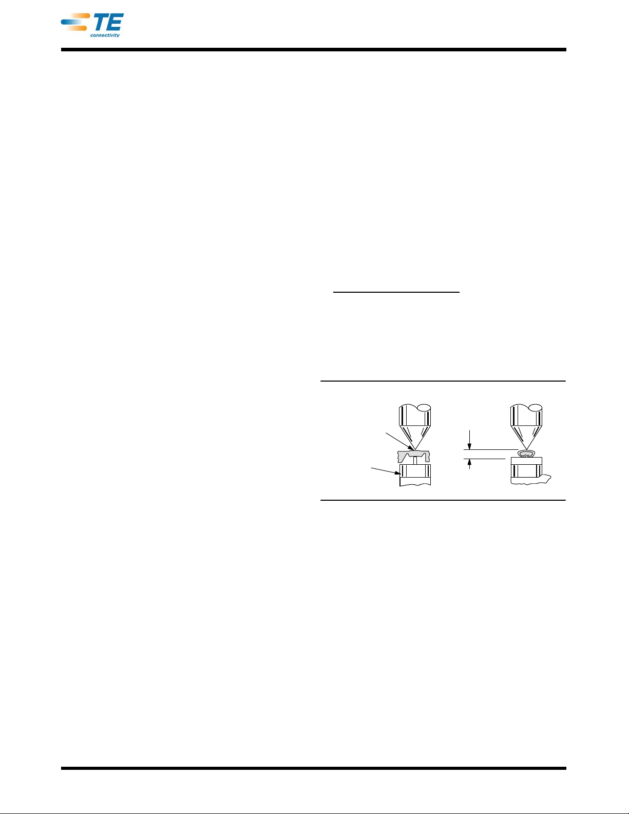
5.4. Crimp Height Inspection
This inspection requires the use of micrometer with a
modified anvil (commonly referred to as a crimp height
comparator) as shown in Figure 3. TE Connectivity does
not market crimp height comparators. Refer to
Instruction Sheet 408--7424 for detailed information on
obtaining and using a crimp height comparator.
Proceed as follows:
1. Select a contact and a wire (maximum size) for
each crimp section listed in the appropriate table at
http://tooling.te.com/data.asp.
2. Refer to the Section 3, and crimp the contact(s).
3. Using a crimp height comparator, measure wire
barrel crimp height as shown in Figure 3. If the crimp
height conforms to that marked on the tool, the tool is
considered dimensionally correct. If not, return tool to
TE for evaluation and repair (refer to Section 6).
Figure 3
Modified
Anvil
Position Point
On Center of
Wire Barrel
Opposite Seam
Wire Barrel
Crimp Height
5.5. Ratchet Inspection
The ratchet feature on these hand tools should be
checked to ensure that the ratchet does not release
prematurely, allowing the crimping dies to open before
they have fully bottomed. Obtain a 0.025--mm [.001--in.]
shim that is suitable for checking the clearance between
the bottoming surfaces of the crimping dies.
Proceed as follows:
1. Select the maximum size wire and strip it
according to dimensions listed in the drawing shipped
with the tool.
2. Select contact and crimp section corresponding to
the selected wire size (refer to the drawing shipped
with the tool).
3. Position the contact and wire in the crimping dies,
as described in the Section 3, CRIMPING
PROCEDURE.
408- 8547
Rev L4of 4
4. Hold the wire in place and squeeze the handles
until the ratchet releases. Hold the handles in this
position, maintaining just enough tension to keep the
dies closed.
5. Check the clearance between the bottoming
surfaces of the wire crimper and the wire anvil. See
Figure 1. If the clearance is 0.025 mm [.001 in.] or
less (on at least two of the bottoming surfaces), the
ratchet is satisfactory. If clearance exceeds 0.025 mm
[.001 in.], the ratchet is out of adjustment and must be
repaired. See Section 5.
The insulation crimper does not bottom on the
insulation anvil.
6. REPLACEMENT AND REPAIR
The replaceable part is listed in Figure 4. Parts other
than that listed in Figure 4 should be replaced by TE to
ensure quality and reliability of the tool.
Order replacement parts through your local TE
Representative, or call 1--800--526--5142.
Tools may also be returned for evaluation and repair.
For tool repair service, call 1--800--526--5136.
7. REVISION SUMMARY
Revisions to this instruction sheet include:
:Deleted web addresses in Section 6
70.36
[2.770]-
76.71 [3.020]
50.04
[1.970]
41.91
[1.650]
220.22 [8.670]
15.75 [.620]
296.93 [11.690]
27.43
[1.080
]
1
29.46 [1.160]
12.19 [.480]
19.81
[.780]
-Closed to Last Ratchet Point Before Release
Note: Dimensions are in millimeters
[
with inches in brackets
]
.
REPLACEABLE PART
ITEM PART NUMBER DESCRIPTION QTY PER TOOL
121045--3 RING, Retaining 4
Figure 4
NOTE
i

Other manuals for CERTI-CRIMP II

1

This manual suits for next models

2

Other TE Connectivity Crimping Tools manuals

TE Connectivity AT-65 User manual

TE Connectivity

TE Connectivity AT-65 User manual

TE Connectivity SDE-SA User manual

TE Connectivity

TE Connectivity SDE-SA User manual

TE Connectivity PRO-CRIMPER III User manual

TE Connectivity

TE Connectivity PRO-CRIMPER III User manual

TE Connectivity PRO-CRIMPER III User manual

TE Connectivity

TE Connectivity PRO-CRIMPER III User manual

TE Connectivity 90017-3 User manual

TE Connectivity

TE Connectivity 90017-3 User manual

TE Connectivity PRO-CRIMPER III User manual

TE Connectivity

TE Connectivity PRO-CRIMPER III User manual

TE Connectivity PRO-CRIMPER III User manual

TE Connectivity

TE Connectivity PRO-CRIMPER III User manual

TE Connectivity AMP 3K Reference guide

TE Connectivity

TE Connectivity AMP 3K Reference guide

TE Connectivity 2063525-1 User manual

TE Connectivity

TE Connectivity 2063525-1 User manual

TE Connectivity AMPOWER 68361-1 User manual

TE Connectivity

TE Connectivity AMPOWER 68361-1 User manual

TE Connectivity 2390882-1 User manual

TE Connectivity

TE Connectivity 2390882-1 User manual

TE Connectivity ERGOCRIMP 539671-2 User manual

TE Connectivity

TE Connectivity ERGOCRIMP 539671-2 User manual

TE Connectivity CERTI- CRIMP Series User manual

TE Connectivity

TE Connectivity CERTI- CRIMP Series User manual

TE Connectivity 46073 User manual

TE Connectivity

TE Connectivity 46073 User manual

TE Connectivity 2407132-1 User manual

TE Connectivity

TE Connectivity 2407132-1 User manual

TE Connectivity 2063379-1 User manual

TE Connectivity

TE Connectivity 2063379-1 User manual

TE Connectivity ERGOCRIMP 1-1579001-3 User manual

TE Connectivity

TE Connectivity ERGOCRIMP 1-1579001-3 User manual

TE Connectivity SDE-SA User manual

TE Connectivity

TE Connectivity SDE-SA User manual

TE Connectivity SDE-SA User manual

TE Connectivity

TE Connectivity SDE-SA User manual

TE Connectivity 58422-1 User manual

TE Connectivity

TE Connectivity 58422-1 User manual

TE Connectivity SDE-SA PN 2063626-1 User manual

TE Connectivity

TE Connectivity SDE-SA PN 2063626-1 User manual

TE Connectivity SDE-SA User manual

TE Connectivity

TE Connectivity SDE-SA User manual

TE Connectivity 2359761-1 User manual

TE Connectivity

TE Connectivity 2359761-1 User manual

TE Connectivity 58425 Series User manual

TE Connectivity

TE Connectivity 58425 Series User manual

Popular Crimping Tools manuals by other brands

Cembre B540ND-BVE Operation and maintenance manual

Cembre

Cembre B540ND-BVE Operation and maintenance manual

KUDOS HD-BGD3 SAFETY OPERATING & MAINTENANCE INSTRUCTIONS

KUDOS

KUDOS HD-BGD3 SAFETY OPERATING & MAINTENANCE INSTRUCTIONS

Textron Klauke K 15 instruction manual

Textron

Textron Klauke K 15 instruction manual

HRS HT803 instruction manual

HRS

HRS HT803 instruction manual

molex Perma-Seal 64005-4500 manual

molex

molex Perma-Seal 64005-4500 manual

molex 63819-3800 manual

molex

molex 63819-3800 manual

VEVOR HS-30R user manual

VEVOR

VEVOR HS-30R user manual

Tyco Electronics 58649-1 instruction sheet

Tyco Electronics

Tyco Electronics 58649-1 instruction sheet

Emerson Klauke EKM 60IDISM manual

Emerson

Emerson Klauke EKM 60IDISM manual

JAE 3502-MX80-2 Operation manual

JAE

JAE 3502-MX80-2 Operation manual

Textron Greenlee GATOR EK425L instruction manual

Textron

Textron Greenlee GATOR EK425L instruction manual

Textron Klauke ESM 50CL manual

Textron

Textron Klauke ESM 50CL manual

Tyco Electronics SIMEL Autocoup CC040 Cof. + charg. manual

Tyco Electronics

Tyco Electronics SIMEL Autocoup CC040 Cof. + charg. manual

Deutsch DTT-12-02 Instruction guide

Deutsch

Deutsch DTT-12-02 Instruction guide

molex 207129 Series Specification sheet

molex

molex 207129 Series Specification sheet

FCI HT-1038A manual

FCI

FCI HT-1038A manual

Gates GC32TSi Safety and operation manual

Gates

Gates GC32TSi Safety and operation manual

DDK DK-5 instruction manual

DDK

DDK DK-5 instruction manual

manuals.online logo
manuals.online logoBrands
  • About & Mission
  • Contact us
  • Privacy Policy
  • Terms and Conditions

Copyright 2025 Manuals.Online. All Rights Reserved.