This manual suits for next models
1
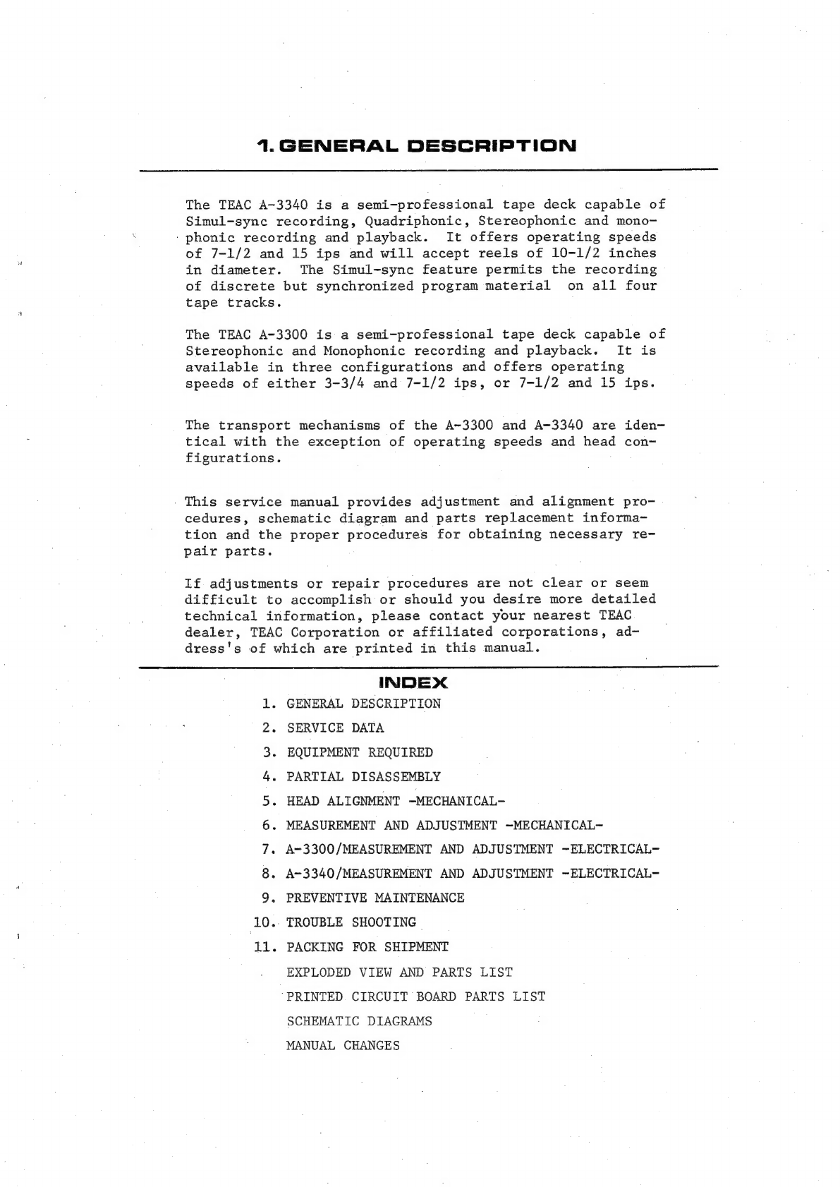
Table of contents
Other Teac Tape Deck manuals
Teac
Teac A-3300SR User manual
Teac 3340S User manual
Teac A-6010SL User manual
Teac AL-700 User manual
Teac A-3340S User manual
Teac X-300R User manual
Teac A-4300SX User manual
Teac A-7300 User manual
Teac A-3300SX User manual
Teac X-2000R User manual
Teac A-7300RX User manual
Teac A-6100 User manual
Teac A-3440 User manual
Teac Tascam 3030 User manual
Teac A-6010GSL User manual
Teac X-2000 User manual
Teac A-1250 User manual
Teac A-2340 User manual
Teac X-7RMKII User manual
Teac X-3R User manual
Teac X-1000R User manual
Teac A-6100MKII User manual
Hitachi
Hitachi D-980MU Service manual
Hitachi D-900BS Service manual
Kyocera
Kyocera D-611 Service manual
Kenwood
Kenwood KX-W595 instruction manual
Akai
Akai GX-630D Service manual
Sony
Sony DTC-A8 Service manual
TANDBERG
TANDBERG 11 instruction manual
Sony DTC-670 operating instructions
Pioneer
Pioneer H-R99 KCU Service manual
Tascam
Tascam 34B operation & maintenance
Akai GX-230 Operator's manual
Akai GX-215D Preliminary service manual
Technics
Technics SV-DA10 operating instructions
Akai GX-370D Operator's manual
Advent
Advent 201 Service manual
Pioneer RT-1011L Service manual
Kenwood KX-79CW instruction manual
Revox
Revox A77 operating instructions