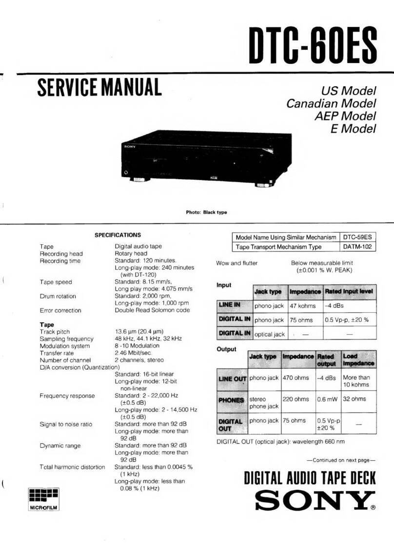
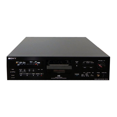
Sony DTC-1000ES User manual

SERI|ICE
MANUAL at,
:Ér.\ AEPMdel
UK
Model
System
Tape
Recordingsystem
Recordingtime
Tapespeed
Drum
rotation
Errorcorrection
Numberof channel
D/A
conversion
Frequency
response
Signalto noise
ratio
Dynamic
range
Totalharmonicdistortion
Wowand
flutter
InDut
Oigitalaudio
tape
recorder
Digitalaudio
tape
Rotaryhead.
1æminutes
(with
DT-120)
8.15
mm,|s
Approx.2,000
rpm
Double
ReedSolomoncode
2channels.
stereo
1ôbitlinear
2-22,W Hz
*0.5
dB
Morethan92dB
More
than
90dB
Lessthan0.0055%
Below
measurablelimit
SPECIFICATIONS
General
Powerrequirements
Powerconsumption
Dimensions
Powerrequirements
Dimensions
Weight
220VAC,50/60H2
(AEP
model)
24OVAC,50Hz
(UK
model)
48W
Approx.470x10ox42Qmm (w/h/d)
(18t/,
x 3ts/r6x
1
6
t/, inches)
incl.side wood
Approx.
430x 100
x420mm (w/h/d)
(16r/r,
x 3r5l,.x 16% inches)
excl.side wood
Approx.12kg (m lb 7 oz)
incl.
side
wood
3 V DC,with R6
(size
AA)
batteries
Approx.
67
x175
x 18
mm(w/h/d)
(2s/"x
6'
/rxn
/r.inches)
Approx.145
g (5
oz)
incl.batteries
Weight
Supplled
accessorles
Remotecommander
(1)
.--..RM-R1
SonybatteriesSUM-3
(NS)
(2)
Audioconnecting
cords
(2
phono
plugsx2
phonoplugs,
stereo,
forlineinputs
and
outputs)
(2)
Screwsto securethecabinet
(4)*
Remote
commander
(supplied).....RM-R1
Remotecontrolsystem Infrared
control
Tape
Track pitch
Sampting
lrequency
Modulationsystem
Transter
rate
13.6
gm (20.4yml
48 kHz,44.1
kHz,32 kHz
8-10 Modulation
2.46
Mbit/sec.
(before
modulation)
* Thesidewood
panels
on bothsidesof thedeckare
detachable.
Afterremovingthescrews,securethe cabin€fi
withthesupplied
lockscrews
(tour
M4x6).
Forsafety,beforedoingthis,besure
todisconnect
the
AC
power
cord
fromtheAC
outlet.
DIGITAL
AUDIOTAPE
DECK
Input
jacks Jack
type lmpedance Rateclinput level
LINE
IN
DIGITAL Phono
Phono 50 kohms
75ohms -10 dBs
0.5Vp-p
Output
iacksJack type lmpedance Ratedoutput Load
impedance
LINEOUT
HEAD.
PHONES
DIGITAL
OUT
Phono
Stereo
phone
Phono
470ohms
150
ohms
75ohms
- 10
dBs
0-28
mW
0.5
Vp-p
More
than
10kohms
32ohms
75
ohms
SONY

DTC-|(NxrEs
SAFETY.RE
LATED
COMPONENTWARNING!!
COMPONENTS
IDENTIFIEDBY SHADINGAND MARK
7\ oru rxe scHEMATrc DIAGRAMs AND rN THE
PARTS
LIST ARE CRITICAL
TO SAFE OPERATION.
REPLACETHESECOMPONENTSWITH SONY PARTS
WHOSEPARTNUMBERSAPPEAR
AS SHOWN
IN THIS
MANUAL
OR INSUPPLEMENTSPUBLISHEDBYSONY.
TABLE
OF
CONTENTS
Description Page
Outline 3
BlockDiagram... 7
Disassembly 13
Adjustments LI
Mechanical
Adjustment L7
ElectricalAdjustment ..... ....20
Diagrams. 32
MountingDiagram
(MD
Servo&DigitalBlock). ....33
Schematic
Diagram(MD ServoBlock). 37
MountingDiagram(Power Block). 43
SehematieDiagram(PowerBlock). ...... 44
Schematic
Diagram(Digital Block) . 47
Mounting
Diagram(Anatog& Microcomputer
Block) .
SchematieDiagnam
(Analog& Microcomputer
Block).
ExplodedViews and Parts List 69
Eleetrical Parts List 79
FlexibleCircuit Board Repairing
r Keepthetemperatureofthe
solderingiron around270"
C
duringrepairing.
. Donottouchthe
solderingironon
the
sameconductorof
thecircuitboard
(within
3
times).
o
Becarefulnot to apply
force
on theconductor
when
solderingorunsoldering.
Notes on chip component replacement
. Never
reuseadisconnected
chip
component.
. Noticethattheminusside
ofatantalumcapacitormaybe
damaged
byheat.
Title
Section 1.
Seetion2.
Seetion3.
Section4.
4-1.
4-2.
Section5.
5-1.
5_2.
5-3.
5-4.
5-4.
5-5.
5-6.
Section 6.
Seetion?.
-2-

DTC-|O(XIES
SEGTION
1
OUTLINE
EPowER swltch
El cags"tt" comparlmont
Inserta cassette
withthewindowside
upandthe
satety
tabfacingtoward
you.
E]sflnr lD button3
end Indlcetors
Us€dto wrlteanderasethestart
lDcodes,
andto
renumberanderase
theprogram
numbers.
AUTO
(automrtlc): Ressto writethestartlD
automatically
during
recording.
Whentherecorcling
levelreturnsto thetixedlevelatter
havingbeen
below
it tor morethan3 seconds,
thestartlD is written
on
thetape
for9 seconds.
MAN(mrnual): Pr€ssto writethestart
lDat the
desired
point
during
recording.
TheMANindicator
lights.
The
startlD is writtenon thetape
for9
seconds.
ERASE:
Pressto erase
a startlD.when a start
lD
anda program
number
arewritten
on thetape,both
codes
aresimultan€ously
erasedby pressing
this
button.
RENUMBER:
Press
to r€number
theprogram
numbers.
When
onlyth€startlDsare
written,
pressing
thisbutton
will ins€rt
program
numbers.
Whenthisbutlon
is pressed,
thetape
is rewoundto
theb€ginning
automatically
andprogram
numbersare
assign€d
from"1" in numerical
order
Il lcouwen buflons
- IIODE: Changps
thecounter
indication
in thedisplay
window
lromth€taperunning
time,
to elaps€d
time
ot theselection,
to toialremaining
timeof theiape,
anclback
to th€tap€
running
limeagain.
RESET:
Resetsthêcounter
to "0MæS".
MEMORY:
Stores
thepoint
wherethecounter
is
resetin memory.
[slsxtP lDbuttons
andIndlcators
-WRITE: Pressto writea skiplD ontothetape.
ERASE:
Pressto erasea skiplDwhich
is writtenat
th€point
just before
thecunent
position.
@fumeac buttons
(O-9)
ftess to designate
th€program
numb€r.
fl nec LEVEL
(recordlng
loyel)controls
Adiust
therecording
le\rel.
The
outer
knobcontrolsthe
leftchannel
levelandthe innerknobthe right
channel
level.
ITITIMER
swltch
Normally
setto OFF.Used
to start
r€cording
or
playback
at thedesired
timeusinga commercially
availableaudio
timer.
@ xenoexonEs Jack
(stereo
phone
jack)
F6-l
Remotesensor
fl: oeenlclosE buttonandIndlcalol
Ef"p" oporatlon
buttons
t STOP
button
> PLAY
button
>> CUE
(fast-forwardrcue)
button
<{ REVIEW
(rtwlndrr€Ylewl
buiton
Fl{ AllS: Pressto læatethebêglnningof the
s€lection
in re\rersedirection.
1r; AMS: Pr€ssto locat€
thebeginningol ihe
sebctionin foruard
di.ection.
O REC
(recordlng)
button
ll PAUSEbutton: lf thepause
modecontinues
for
about
10minutes,it will bereleased
automatically
andthed€ckwillenterthestopmode.
O RECMUTE
(rocord
mutlng)bullon
@cteln bunon
Used
to cancelthesel€ction
number
which
hasbeen
entered
mistak€nly.
@sxtr swncl
Set this switch to ON to skip during playback the
selections cod€d with a skip lO code. S€t it to OFF to
play back the whole tapê as it is.
@tneur sELEClswlrch
ANALOG:Forrecording
frorn
theequipment
connecl€dto theLINElN lacks
on therear
panel.
DIGITAL:
Forrecording
fromtheequlpmenl
connect€dto theDIGITAL
lN lackon th€ rea.
pan€|.
lielstlnl unon
Starts
playback
tromthed€signatedselectlonor
aclivates
themusic
scenop€ration.
@exones LEVEL
(headphones
level)control
-3-
*r! ';: ' -- : r'

DTC-I(noEs
liglcouNren
indicatol
Lights
up
to show
that
the
counter
isdisplaying
the
tape
running
time.
lisl
aeuntNttlo indlcatol
- Lights
up
to show
that
thecounter
isdisplaying
the
remaining
time.
Theremaining
timeis notdisplayed
during
searcn
ooeration
(the
SEARCH
indicator
lighls)'
fast
fonatarding
or rewinding
hluemonv indicator
Lights
upwhentheMEMORY
button
is pressedto
show
thatthe " 0M00S"
pointis stored
in memory
lâ-lpcu llME (programtlme)
indicator
Lights
up
to show
that
the
counter
isdisplaying
the
elapsed
timeof thecurrent
selection
Eleuexlsts indicator
"Light. up
whenrecording
a digital
signal
input.from
thé
DIGITAL
lNjack
contains
a pre€mphasized
signal
In
the
playback
mode,
it also
lights
up
while
the
detected
preemphasized
signal
is being
de-
emphasized
@ eou (programnumber)
disPlaY
Shows
theprogramnumber
of theselection
being
played.
Edlns (automatic
music
sensor)
display
"sno*i the
number
of selections
to beskipped
ahead
orbehind
inAMS
operation.
When
a numeric
butlon
isoressed,
the
display
shows
the
program
numoer
or
thetarget
selection
while
theselection
is being
searched
for'
lâslcopv PRoHlBlr (digital copy prohlbit) indicator
-Blinks when the digitalsignal
to be recordedcontains
a "digital copy prohibit"code In this case,
digital-Îc
digitalrecording
cannotbe done.
EClclurtot't indlcatol
Blinks
when moislure
condensalion
occurs lf this
happens.
the deck stopsautomalically
lâTselncn indicaior
Lightsup whilea selection
is beingsearched
lor
IâClsrnnr
tD
indicator
Blinks
when wrilingor erasing
a slart lD code,
or
when the start lD is detected during playback.
lzglsxtp
tD
indicator
Lightsup momentarily
when writingor erasing
a skip
lD code,
or when the skip lD is detected
during
playback
@ Sampling lrequency indicators
fndicates the sampling frequencies(32kqz, 44.1
k{z,
4BkHz)
with which the digitalprogram
is encoded.
44,1 kHz: For playback of prerecorded DAT tap€
(Digital-todigitalrecording
cannot be done.)
48 kHz: For recording/playback
with DAT tape
lSilpeak level metêrs
Indicate the levelot the audio signal being recorded
duringrecording,
and the peak
valuesof the audio
signalrecorded
on the tapeduringplayback.
15â
counter
Displays the tape running time, elapsedtime of the
selection
beingplayed,
and the total remaining
time
of the taoe.Each
time COUNTER
MODE
is pressed,
the display
modechanges
in turn,
-4-

DTC-IOOOES
mc-ro0oEtt
lrst HoDE
For DTC-1000ES,the internal CPU modescan be
displayed for servicing on the counterts seven-
segmentdisplay.
The following modesean be displayed:
Mechanical
operation
(Meehanical
mieroeomputer
operation)
Mechanical
instruction
(Main mierpcomputer
instruetion)
Operation/operation
eompletion
End sensor
normaVabnormal
Cassettehalf existence
OPEN/CLOSE
Tape end (take-up)/normat
Tape end (supply)/normal
A/B head RF existence
WIDTH I.5 tirnes normal speed/NOT 1.5 times
normal speed
Soft tape/normal tape
REC inhibit/OK
Drum normal/abnormal
Tnay in/out
TEST mode/NOTTEST mode
Take-up end hold/NOT hold
Tray loading normaVabnormal
Position
EJECT/NOT
EJECT
Measure
End
Fiæ;a
Take-up Reel Stop
Supply Reel Stop
Measure
completion
To dlsplay the test modes,conneet pin 6? of
meehanical microcomputerIC512 to GND, and
press the eounterrs MODE switeh for three
times.
(c) The indicator display is deseribed
below.
Using indieators (1) through (9), data in main
mierocomputer is displayed by four bits
(hexadecimal).
0tems (l), (3), (4), (5), and (6) are mechanieal
mieromcomputer data; (2) and (g) are main
mieroeomputer data; and (8) is reel
microcomputer
data.)
REMAINING PGMTIME
COUNTER MEMORY
-l=1,
l--t
Fj",g
fl,
e @@ @@
EMPHASIS
E
E
E,5,5
--tl,-l
@@ @@
COPY
PrcH|B
CAUTIC
SEARC
E
E
-6 -3 o ovE
-lo
;R
(a) æ -50 -40 -30 -20
(b)
Display
position Deseript ion
oMeehanical operation
@Mechanieal instruetion (main micro-
eomputer to mechanieal microcomputG
@
0
I
2
3
Operat ion mode (OPERATlol{/
ooTFL-E,MN)
End sensor (NORMAL/ÂEffiFED
Cassette hal f (yEs/No-)
oPEÀr
(oPEr{/c-ffiE)
@0
1
2
3
Tape end take-up reel (lOPlNqT)
Tape end supply reel (El{D/NOR)
RF (NO RF/RF)
WIDTH (15 TIMES NORtritALSPEED/Nd
ffi)
@0
1
2
3
Tape (soFT/ffiL)
REC
(
INHIBIT/M)
DRMERR
(
DRI'MNORIT,IAL
/AB-rem T)
TOIJT (TTAY IN/ôTT)
@0
I
2
3
FTEST (TEST MCDE/NdÎ-MSFI'FDE)
îETDH (TAKE-UP EIID HOLD/MLI
TI,ABF (TRAY LOADITG }ORMAL/
ÆmFm[)
PEJCT (EJEC,îlos IT IO.r/FOIffi
FôSTT'IN)
@0
1
2
3In., ur"o. (Digit
may
vary.
)
@0
I
2
3
@0
I
2
3
Not Used. (Oigit may vary.)
Measure complet ion (æMPLETED/Ni
coilr-FfErED-)
-5-
D[C-toooEs
(O Display positions (1) an<l
(2) are shown below.
(The same data es in (2) is displayed in (1) at
all times with a slight delay.)
Code Display Deseription
0
1
2
3
4
5
6
7
8
I
A
B
c
D
E
F
,-l
,J,
,
L:I
:]
L'I
,:
-,
E
.?
a
Lg
:
b
t--
Ll
;_:
Blank
FWDxI
FIID x 2
FlllD x 16
REC FIYD
FF
FF SEARCï
FIVDx 16 (measure
)
OPEN/CI.oSE
STOP
PAUSE
REV
x l6 (measure)
REW
REWSEARCTI
REVxI
REVx2
REV x 16
(e) Operations in the TEST mode are described
below (as eompared with those in the normal
mode).
1. Cassettecompartmentis not activated.
2. Cassette is not deteeted.
3. CAUTION indication does not aPPear.
The DTC-10008S eannot enter the TEST mode
from PLAY mode. When the AMS button
( >l ) is Pressed uslng a 1.5 times normal
speed tape, FS (sampling freqnency) indication
changæ to flashing 32 Wlz and the set enters
the FWD mode. Whenthe AMS button ( fi )
is pressed,
it enters the REV mode. Whenthe
former button is pressed using a normal speed
tape, the set enters the FWD x 16 mode. When
the latter button is pressed,it enters the REV
x 16 mode.
-6-

Audio/fiercconputer
SECTION
2
BLOCK
DIAGRAM
rcr04 cl200t8 a/0 c0nvERTfR
tr *l'fçrniÀA]
s€RVo6LOCk
THE CIRCUIT
Ift R CH IS OHITTED BECAUST
II IS
IHE sÀME ÀS TIÂT il L.CH
sEnvo
qæx
o
t
_ , s782
I!il€p oFF{
I Ê
I RÉcr
It
-,_, flLCPO(*pulaP
.'- FORtErctt COTTiOL
TTIî1
a!6
acx
aÈô
nÉx
J5TL
AIO I
RFIIH
XTAL AFi€C
MrCn0CoMPUTlR
PtI
s=")
-7-

&( rc( Lrc( m-?
xl2l
rrlEtrlcE cLxr
LR03 rc_
!Êo? PRGE
LRol Pltu
xooE
i:ÉEà9E
l:zâ--âgt
nx Tx
Àtll aær
il0I
FFO ERPF
DlG1lÀ! l/0 tsl2l
3:
iÈ:=l:;*ç--ai
LEVEL I''EN
0ll
tc354
cx0
||to0
tG8
TEVEL TEIER
CdTROL
rc
703
rsil58422
ÀF8
Âæ9
ft
OART
CSET
PREil
sæ@E
r/
AfI OE'E(
É -ê
6t
t0t.75r-781
FLTOI
)FtscEtt
LÀt
t[01
J-
-8-

É{ lÊcx @r æ mF r7,0 rtr r
et0T
PSOT
caol
RTPB
DTC-|(XIOES
T902
\, /--{ol l016rrAL
ourl
iltr
ilP I
- REC
SIGÈÂL
PO
SlGIAL
-4'
LEVTL
f,ETTR
L-14
lFMutrl
-9-

Itrc-l(xxlEs
Sewo
cfslat {toR
re
rl5TRÆ( YlfrH GSETTE oETEd Sv
C6ÊTTE DETECTST
ru ENAN EIECT
SOfl ]APEDEIEfrSI
ca$ETTE1Ær€ Wt EECT St
CGEITE TÂ81€OUTOEECÎ
firMDriG rllrT oETECÎ
- 10-

prc-rqpEli I
fù o*u*
uoto,
v
,1 Dt*-c0N0t15t
''' pcottct rtrT€P
' REELTOIæ
-ÉffFr corrmL
r=-::i-1
-{-l ,'""'"%
l-------O ''ÊEE-
xoroP
FvS9 l(5!.OS,5zll
ftDloqNt-

BCÉ ÀCH
"\-!Em
,\-$9!l--
"\-l!!9!!-
or-Jg!r-
ô\-!r!]lsw-
QAX
94I rc5t8
cx0t0520
NlCROCOilPUTER
FON
ORUM/CÀ6TAN
SEM
R'OTI
;ÊËEa
Él*{Ë#
,rr
ipjEÉË ?:EË :
ntrruP
*'*'3 J5=3
LI
ft60
f{0
s(EO ,c5t2
IMP'?C460AF
R€FwD rrcRocorPultR
RE5ÎOP FOF
UECHÂN|SM
RacEtr Ql
Itt0
R/W PLffiII
\ACr PLilOt
xac( E0-?
lRsl
l9E0
tc5t0
IIP{7C8@
-, rrcRocdPurEF
-' foF qEEL
srm
-11-

Whennumbersare assigned
in the illustration, removeparts in numericalorder.
[Outer Cssirg (Prqrt/Rear Case)]
Dressplate l9B3x6
3Spacer
OM4x20
(with ringl o8vTI3 x6eB3x6
-}aSpacer OBVTT3
X
8
ô
ot x
-!ç,.
i/; Jaek plate
,j Oavrr
ll 3x8 4."
vOBVTT
3x6r.
6tuttô
3X Oevrrg
x
s
(3 tn all)
Oaeexs Dressplate
t
OBvrr3
x8
(4 in an) \D
CM4x?o
(with ring)
Front panel
- 13-
I orc-tqroqs
I
sEciloN
3
DISASSEMBLY
[tain tierpcomputer Bosrdl
Push the tab in the direction
indieated by thc affow and
Demove the boârd ll
(at five locations). \"R
[Operatim BoùdI
Push the tab in tl|e direction
indicsted by the arrcw 4 a
I,t l"ToI" the
board-B
(at eight locations). h

DTC-|(XpEli
:Andog Boqrd]
TR heat sink TR sugport plate
BVTT3
X I
O
S(s in au)
Jcopp". *"rh".
TR getscrew
Analog board
Operation board
IEscutcheon]
escuteheon
BTP2.6
X 8
(2 in all)
K
Pushboard supporter (B) in
indicated by the arrow and
Front panel
- 14-

DTC-|(XTOES
IlaAtg Xotorl
Cassette
compartment Loading motor
[controt [otorl
Control motor
Control motor mounting Plate
o
OPzxz
Preeislon
screw
Remove the belt.

OBz.6x
s
Y $oez.sxs
Oaz.sx
s
[feclnnieal Blockl
Note: Removethe crssette control block while
it is set to OpEN.
Note: The numbergin the illustration indicate
the installatlon order. (Check a UD gear
for lts hole position.)
OPs2.6x
4
g
Motor mountlng plâte
Irstall the UD gear with the hole set here.
I Compresslon
eoll spring
{ Soerrwraxs
I
$Spacer
MD mounting
plate (R)
tDaz
x a
DAT deek meehanism
Supportplate
Drum drive board
g
eaz.sx
s
OP2.6xs
Ogvrtgx ro
({ in all)
Transistor board

I DTC-t(xrOES
SECTION
4
ADJUSTMENTS
+I. MECHAMCAL ADJUSI'IENT
Ifhen the drum rclated bloek is replaeed, finely adjust the tape path (in 1.5 times normal speed FWD mode).
+l-1. T:l cuiè Adjustnent
Adjustmcnt
1. Conneet CH-l of an æcillæcope to pin 1
(RF) of CNT52 and CH-2 of an æcilloseope
to pin 6 (SWP)
of CNT51.
2. lrrn on the power switch, insert alignment
tape TY-?251 (8-909-813-00),
and put the
set into the TEST mode.
Press the AMS button, then press the PLAY
( > ) button.
3. Raise guide Tl so that the RF signal
waveform is as shownbelow.
Raise guide T2 and align it with the lower
edgeof the tape.
Iower guide Tl so that the RF signat
waveform is normal.
Check that the tape is aligned with the
lower edgeof guide T3.
lf it is not, repeat Step 4.
Adjwtnert Point
Mechanism
assembly
Guide Tl
Guide T2
Guide
T3
+L-2. Sl Guide Adjustment
AdjustDent
1. Turn on the power switch, insert blank tape
TY-308 (8-892-358-00),
and put ttre set into
thePLAY())mode.
2. Raise guide 52 and align it with tie lower
edgeof the tape.
Note: Check that no curl oceurs at guide 52
in the REW
(( ) mode.
Adjustneit Point
Mechanism
assembly
Guide 52
4.
o.
6.
A=At
-17-

DTC-I(XIOES
r
I
l-l-3. F Guide A$ustment
Adjrstoeot
1. Turn on the power switchr iruert blank tape
TY-308 (S-892-358-00),
and put the set into
the PLAY ( >) rno<le.
2. Align guide F with the lower edge of the
tspe.
Note3 Check that the tape is aligned with
the lower edge of guide T3 and i8 not
curled.
Adiustneit Point
Meehanism
assembly
+r-1. Sl Guide Adjugtment
A-dJustnent
1. Turn on the power swltchr insert blank tape
TY-308 (8-892-358-00), and Put the set into
the PLAY ( )) mode.
2. Align grride 33 with the lower edge of the
tâpe.
Note: Check that the tape is atigned with
the lower edge of guide S3 end is not
curled.
Adiutmot Point
Mechanism
assemblY
Guide F
Guide T3 Guide 53
- 18-

I DTC-lOqrES
l-1-5. T3 Guide AdJurtnent
Adjustment
1. TUrn on the power switch, insert blank tape
TY-308 (8-892-358-00),
and put the set into
the PLAY ( >) mode.
2. Align guide 13 with the lower edge of the
tape.
Note: Check that the tape is aligned with
the lower edge of guide T3 and is not
curled.
Adjustmett Point
Meehanism
assemb$
Guide T3

DTC-I(xxlE!;
+2. BLBCTnICAL
ADJUSTXEIIT
1.
MD servo board (comPonent
side)
O RV5oa
""r0.; o"uoot
*,".'i:i'
RVlo6 OO Rv3o5
(J nvoo4OO Rv3o2
RV30l
o
"To"
CNT33
I
Onvcr
t
O nvsog
O
nvsro NT5
t
OFF
OFF
DIGTTAL
MIN
I\[IN
AUTO
Perform the edjustment in the order
deseribed.
Use the following alignment taPes:
TY-?111
(S-909-812-00)
TY-?251
(8-909-813-00)
TY-?551
(S-909-814-00)
TY-308 (8-892-358-00)
Use the following torque meters
TW-?131
(S'909-?08-?1)
TW-?z31
(8-909-?08-?2)
hitial settings are as follows
Timer
Sktp
INPUT select
REC volume
HEADPHONE
volume
Counter mode
3.
ç2-1. Ff/RBf Torque A-dnltm€nt
A<ljustment
1. Ttrrn m the power switch and insert FF/REW
torque meter TW-?231.
2. Put the set into the TEST mode.
3. Put the set into the FF ( >| ) and RBW
( << ) modes and check that the torque
is l? to 18 gem.
If it is not, adiust RV509 (FF mode) and
RV510(REWmode).
4. After adjustment is completed' caneel the
TEST mode.
Note: Be sure to adJust the torque in the
following order:
(r) rr torque
(2) REw torque
(3) FWD baek tension
A$ustmot Point
MD servo board (comPonent
side)
o8
rI
o88
RV509
/e
%
1o
\
RVSIO
o
Table of contents
Other Sony Tape Deck manuals

Sony
Sony DTC-87ES User manual

Sony
Sony DTC-670 User manual

Sony
Sony DTC-790 User manual

Sony
Sony DTC-1000 User manual

Sony
Sony DTC-77ES User manual

Sony
Sony DTC-ZE700 User manual

Sony
Sony TC-378 Setup guide

Sony
Sony DTC-87ES User manual

Sony
Sony PCM-R500 - Dat Recorder User manual

Sony
Sony DTC-790 User manual

Sony
Sony DTC-57ES User manual

Sony
Sony TC-765 Setup guide

Sony
Sony TC-854-4 User manual

Sony
Sony PVW-2650 Service manual

Sony
Sony DTC-57ES User manual

Sony
Sony DTC-690 User manual

Sony
Sony DTC-60ES User manual

Sony
Sony TC-560D Setup guide

Sony
Sony TC-388-4 User manual

Sony
Sony MDS-JA50ES / Mode d’emploi User manual