manuals.online logo
Brands
  1. Home
  2. •
  3. Brands
  4. •
  5. Team Losi
  6. •
  7. Motorized Toy Car
  8. •
  9. Team Losi LX-T User manual

Team Losi LX-T User manual

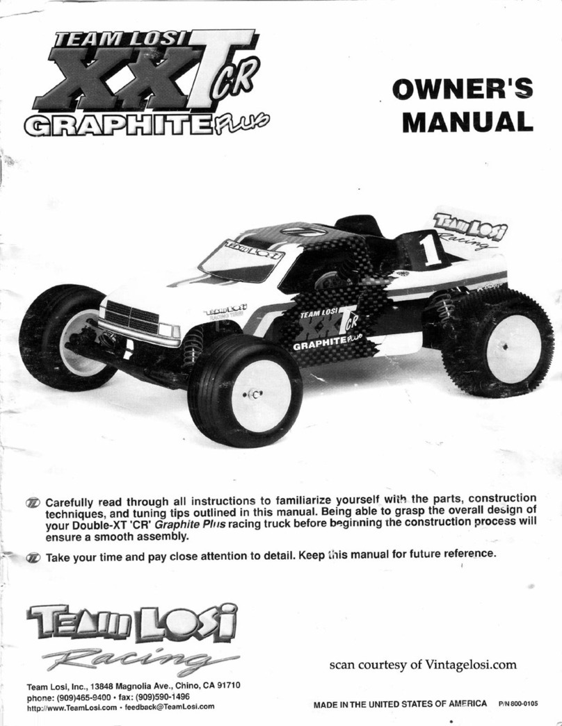
OWNER'S
MANUAL
• Carefullyread through all instructions tofamiliarizeyourselfwith the
part
.s,construction, techniques
and tuning
tip
s outlined in Ibis manual. Being
ab
le to
grasp
the
overall design
of
your LX·T racing
truck before cons
tru
ction will ensure a smooth assembly.
• Takeyour time and payclo
se
attention to detail. Keep this
ma
.nual for
tuture
rd'ereace.
TEAM
LOSIINC.
,CHINO,
CA.
11710
PIN
__
, ca-.-"'
MADE
IN
UNITED STATESOFAMERICA
...
\F;rmlfl1V
-;e:~
LX-T 'XX' RETRO TRANSMISSION ADDENDUM
The
Team
Losi
LX-
Tracing truck
kit
that
youjust
purchased
has
been upgraded.
It
now
inc
lud
es
the 'XX' Retrofit
transmission
.
This
makes
the
unequaled
performance
of
the LX-T
truck even better.
Along with
this
addendum,
you
will
also
find
enclosed the LX-T instruction
manual
along
with
the 'XX' transmission instructions.
Please
read
through
all
instructions before
beginning
assembly
. This
will
help
familiarize
you
with
the
assembly
process.
Locate the LX-T
manual
and
highlight
the
following
pages
and
assembly
steps.
When
you
reach
these points
in
the LX-T
manual
,
begin
using
the 'XX' instruction
manual
until
the
transmission
is
completed.
Then
resume
using
the
LX-
T
manual
.
PAGE
BAG
FIG.
sn;p
NOTES
When you reach page 10,
bag
C,
begin assembly on the 'XX'
10-
14 c
8-29
1
-35
transmission. When assembly of
the
transmission is complete,
return
to
page 15, bag 0
of
the
LX
-T manual.
Ignore steps 24 -27 in the
LX
-T manual. When you reach this
19-20 D
40-41
24-27
point in assembly install the dogbones from step
26
in the "XX'
transmission instructions. Once both dogbones are insta
ll
ed
retum
to
step
28,
page 20 in the
LX-T
instructions.
"N01e:
This LX-T
kit
has
also
been
updated to
include
Team
Losi's new Silatech shock
fluid
Jn
the LX-T
manual
, reference number (114)
has
been
changed
. Number (114)
is
now Team Losi
350 Silatech shock
fluid
, part
number
A-
5224.
If
you replace the gears
in
the
'XX'
transmission
supplied
with
this
kit
, be sure to use the
2.
61
:I ratio gears
(part
numbers
A-3076
and
A-3077).
The 2.
19
:I ratio gears
will
not work
unless the transmission cases are also changed.
Do
not
be
alarmed
ifthe idler gear
and
diffgear
supplied
with
your transmission are black
or
have
black
markings
on
them. This
is
for
identification purposes only, and
is
necessary so that
the 2.
19
:I gears
and
the 2.
61
:I gears
can
be
separated
for
packaging.
We are sorry
for
any inconvenience
this
may
cause. The
'XX'
transmission was added to
the LX-T as soon as possible. Together,
they
make
the most competitive racing truck
available
.
Good
Racing.
Team
Losi
Literature II 800.0050
WELCOME, LX-TOWNER!
Thank
you
for purchaalng
the
TNm
Losl LX-T. Thla
kit
repi'8Nnta
the
lateat In 1/ 10 acale re
cl
ng
monaler truck
technolOgy.
The
LX-TendIt'apredeceaeor,
lhe
JRX-T,have
won
everyR.O.A.R. NetlonelChamplonahl
plo
dele
utilizing
the
exii'IIOI'dlnary dealsln end conatructlon that h
..
made
TNm
Losl temoua
WOI'kf
Wide
.
The
uae
of
specialized
meterllla
, computer aided
detlgn
(CAD) and finite
element
enalylll
(FEA
11rn1
analysis) Ia unequalled
In
the
RI
C
re
cl
ng
WOI'kf
.
Beforesterling
conllructlon
of
yow
LX-T,pleaaetakea moment
to
reed through
theM
lnltrucllona
. This
will
minimize
buildi
ng
time
and
get
you
to
thell'llck
sooner. Additionally,
we
haveIncludeda
tech
tip
aectlon
to
helpyoull'llck
tun
e
yo
ur
LX-T
for
optimumperformance.
Once
again, thank
you
for choosing
the
LX-T.
TNm
lolllsreclng
to
help you win.
TEAM
LOSI
1. INTRODUCTION
LX-
T CO
MP
LE
TE
D
KIT
DIMENSIONS
Length: 16.00 ln. Front Wid
th:
12.50 ln.

Rea
r Width: 12.25 in. Height: 6.00 in.
Wh
ee
lb
ase: 11.375 in.
All
dimensions at ri
de
he
igh
t.
We
i
ght
ma
y va
ry
dep
ending
on
accessories.
KIT/MANUALORGANIZATION IMPORTANTSAFETY NOTES
TheTeam Loal LX-T
Kills
composed
of
differentbega
marked Beg A
ttvough
Bag G. Each beg contalna all
of
the
parts
nece.
..
ry
to
complete• certafneectlon
of
the
truck.
II
Ia
HMnllel
that
you open
only
one beg at 1
timeand
follow
the
rightaequence, otherwlaeyou mey
flee
dlfflcultlea
In
finding
the
right part. II
Is
helpful
to
rNd
the
entire Instructions
for
e beq prior
to
stertlng
euembly
. Key numbers (In clrclea) have been ea-
algned
to
each pert and remeln
the
aeme throughout
the
lnllructlona
. For
your
convenience,
en
actual aWl
hardware lclentlflcetlon guide Ia Included with N ch
step.
To
check
e pert, hold
ltega
lnat
the
allhouetteuntil
Ills
Identified.
In
some ceaea
ex1111
hardware
has
been
supplied
to
replace
Nally
loll
perle. When
auembllng
1118111
to
plaatlcperle,differentfilae.g.presa, net, looae
havebeendealgned I
nto
the
parts.To enaurethat
peril
are
not
loll
duringconstruction,ItIasuggestedthatyou
work
over1 towel
or
met
to
prevent
peril
from rolling
away.
-i-
1. Select an area
for
euembly
that Ia away from the
reach
of
smell children. The parta In
the
kit
ere small
and
can
bo
swallowed
by
ch
ildren
causing choking
and
possible lnternallnfurles.
2.
The
ahockfluid
end
greaaeaaupplledahoulcl
be
kept
out
of
children's reach.
They
are
flO(
toxic but
we
re
not
Intended tor
human
consumption
.
3.
Ex
ercise care
when
using
any
hand
tools
1
lherp
lnatrumenta,
end
po-
toola duringconatruct1on.
4.
caretullyr
ea
d allmanufacturer'swamlngs
and
cautions
for
any
gluea
or
pa
lnta
that
mey
be
uled
for
euembly
purpoaea.
INTRODUCTION (Continued)
TOOLS REQUIRED
Team Losl
has
supplied all allen wrenches and a spe-
cial wrench that
is
needed
for
assembly and adjust-
ments. The following
common
tools will
also
be re-
qu
ired: # 2 Phi
llips
screwdr
i
ver
,
small
flatblade
screwdriver, needle
nose
pliers,regularpliers, scissors
or
other
body
cutling/
trlmming
tool. 3/16'', 1/4
",
and 3
/8"
nut driversare optional.
RA~IO
/
ELECTRICAL
The LX-TTeam LoslRacing
Truck
is
an
out-of-the-box
hi
gh
performance race
truck
.
It
is
for
that reason that
wehave notincluded specific Instructions
on
radioand
electrical equipment.
We
have left
this
subject
to
the
personal preference
of
the
owner
/racer.
A suggested layout Is provided
in
this
manual. Your
hi
gh
performance R/C center should
be
consulted
MOTORS AND GEARING
regarding specifics
on
radio/electrical equipment and
placement.
HARDWARE IDENTIFICATION
When In
question
, use
the
hardware Identification
guide
In each step.
For
screwe,
the
prefix number
designates
the
screw size and number
of
threads per
Inch e.g., 4-40 Is a
#4
screw wfth
40
threads per
Inch
of
length. The fraction following deelgnates length
of
thread
or
overall
if
flathead style. Bearings
and
bush-
ings
are referenced by Inside
diameter
x
outside
diameter
. Shafts and pi
ns
are
diameter
x
length
.
Washers aredesclbed byInside diameter
or
the
screw
size thatwlll
paiS
through
the
I.D.. E-cllps are sized by
the
shalt diameter
of
attachment.
YourLX-T kit
lncludH
e 80
tooth
, 48
pitch
epurgear
. TheInternal gearbox ratio
Ia
2.18:1.The
extem~~l
pinion gearwlll
aet
your
final
drive
gear
ratio. Thefinal driveratio
Is
= 2.18x(No.
of
teeth
on
the
spur
geardividedby
the
No.
of
teeth
on
the
pinion
gear). Example:
Fore
15
tooth
pinion wfth e
80
tooth
a
pur
gear, the final
drive
ratio
would
be
2.18x6.00
or
13.08 :1. Conault
with
lour
high
performance ahop
for
recommendations
to
ault your racing atyle and ciaiS. The
chart below
tibias
Team
osi
motoraand
the
recommended gearing forthait
motor
. Ratioa
can
be
adjusteddepending
on
varloua track
layoull,
tire
sizes and battery
typH.
RECOMMENDED GEARING FOR
TEAM
LOSI MOTORS
MOTOR MODEL NO. PINION SPUR
Big Ed TL 6108 15 90
SuperInsane (Stock) TL
6024
20 90
M
TM
(Truck) TL6104 18 90
Jr'sChoice TL6103 17 90
Motown Missle TL6106 12 90
Off
Road
Special TL
61
10 14 90
TABLE OF CONTENTS
1. INTRODUCTION
Ki
t/
ManualOrganization
...
.
....
......•••
I
ImportantSafety Notes
•..•..
.
.•••••..••
I
Tools Required
•.••••.••
.
..
...
..
...
.••.
II
Radio/Electrical
......
••••.••••..••.••
•. II
Hardware Identification
..
••...
.
...
..
••
...
II
2.
Bag
A
...••..••••.....••.....•••...
1·5
3.
Bag
B
......
. . •
••......
•....
...
••
• • 6-9
4. Bag C .
•....•..•.
..........
...•
•...
1D-14
5. Bag D
......•••..•......
.
•••...•
. . .
15-20
8.
Bag
E
........
.....
........
•..
.
....
21·24
7. Bag F . . . . . .
...•.••.••••••
.....
••.
..
25
8.
Bag G
•••••••••••••••
• .
••
•
•••••••
••
26-28
9. CamberToe In/Out
.....
•.•••
.
••
.
•....
29
1o.Tuning Tips
..•.............
.......
30
11. Spare Parts .
..
•
••
..
••
..
.•
.
.....•
...
31-33
Team
loll
Engi
,_lng
Ia
continually changing and im
pt<Mng
cltllgna;
the<-
.the actual part
may
appear allghtly
dm.r.nt
11\an
the lllustraled part.
ll
ustratlono
of
pano and
uoomblln
may
be
alighUy diSion.d
to
on.,._
f*llnont delll
ll
o.
-ii-
BAG A - FRONT SUSPENSION
·--
(i)
••
0 0
CD
1. Locate
the
front lhoc:k
to_.
(1
) and
a1tech
the
thock
mounta
flc:o
the
canter hole on
the
top
of
the
to_.
u.Jng
2,
x7/r cap head
acrews
(3). Flg.1
2.
l'llrelld
In
•
3/r
b.U
atud (4) Into
the
Inside hole
of
the
three
holes
at
the
bottom
of
the
thock
to_.
(1).
TheM
go
on
the
~Ita
aide
of
the
lhoc:k
mountt
(2).
Secure
the
ball
tludt
(4) with • 4-40 nut (5). Fig 1
I (i)
3. Secure
the
tront
thock
to_.
(1)
to
the front
bulkhead (II)
..
ehown
utlng
two
4-40x 7/r cap head
acrews
(3). Flg.2
2
Figure2
-Page 1-
Figure 1
c
®
BAG A (Continued)
4. Attach
the
front
auspemlon
anne left (7),
right
(a)
front
to
the
front
bulkMad
(8) using 1/r x 1.850 hinge
fine (8)
end
MCure
the
pine (8) wflh
four
1/r E-CIIpe
10) Flg.3
• Note:
Be
$1N8
thatarms(1) &(8) sweep
rea!W81'd
and
shock
mounting
hol
es
are
on
top
.
® 0
®
5. Attach
the
body
mount
slide (11)
to
the
beck
llde
of
the
body
mount
(12)
by
tlnldlng
two 4-40 x
3/r
cep
hNd
screws (13)
Into
the
cent«
hoiH
of
the
body
mountelide (11). Fig. 4
8. Affix
the
body
mount(12)
tothetwo4-40x7
/8acrews
(3) protruding from
the
front
or
the
front
bUikMICI (II)
10
tha1
the
body
mount
(12)
anglel
forward.
Secure
wtth
two
4-40
lock
nuts
(14). lob
\a
IUI'I
tha1
the
body
mountlllde
(11)
anglel
down
tow.rde
the
front
and
noc
the
beck.
Fig. 4
-Page
2-
Figure3
®
Fi
gure
4
•
®
BAG A (Continued)
-···
(.)
CD
®
...
@)
4
19
1.
Slide
tiM
front axle(15)
lntothupindle
(18lleft,
(17)
right
10
ttlllt
tiM
holM
arw
aligned.
Thla
will
now
be
celled a aplndleaaaernbly. Fig. 5
*Nota:
Spindle
'""'
arw
marked
for
left
(L)(18) and
right (R)(17).
~
8. Place
'-ft
lpindle
aaaernbly Into
left
lplndle
center
(18)10the
letter
on
tiM
apindle
(18llacea
up
and
lnaert
a 1/r x .880
hinge
p1n
(111)
through
the
aplndle
center
(18)
and
aplndle aaaernbly
and
aecure
with
two
1/r
£-CIIpa (10). Repeat
tor
right
tide
. Fig. 5.
11.
Center 1/r x .880
pin
(111)
In
lpindle
center
and
tcNW
5-40
Mt
tcNW
(20),
Into
!Wir
of
axle (15) and
up
agalnat1/l!f'x .880
pin
(111)
until
anug. Fig. 5
1o. Thread
one
3/l!f' bell
ltud
(4) I
nto
the top
hole
of
sp
indlecarrier(18)
from
the
rearand
one
3/16''
bellltud
(1
45) Into aplndle
arm
(16), (17)
from
the top
.
Thla
Ia
now
calleda
sp
i
ndle
carrierassembly. Make a
left
and
a ri
ght.
Fig. 5
(.)
® ®
11
. Attach
'-ft
lpindle
carrier
assembly
to
left
auspen.
lion
arm
(7)
ua1n11
a 1/r x .880 hinge
pin
(111)
aecwed
withtwo 1/r E-clfpa (10). Repeat
for
right
tide.
Fig. 8
*
Note
:
S.
sureletter onspindles (
16
& 1
7)
face
up.
18
Figure 5
~/
~
FigureS
-Page
3-
15
BAG A (Continued)
I
®
12.
ThrMd
an
adjUMable
rod
end
(2
1) onto
•ctt
end
ofa 1.871"tumbuclde (22).
ThrMd
boCh
rod
endt
(21)
evenly until
the
owrallllngth
matchH
tM
llluttrttlon
below.
Thll
will
oow
bll'lflrTad
to
11
trontcamberlink.
Make
two
. Fig. 7
•
Note
:
One
end
ol
tvmbucl<le
/Ia
fell
Mild
thle«Js.
n..
m
-
~~~~~
~~~~"'~ilii
~'\•~B
§llllii!i!llil\0
~
~\NNW
. _
¥PUJi't
u
13
. Find
the
lhllt
of
a
foam
rtngal:3
)
and
r.move 4
from
the
lhllt.
l'tac:.
one
toam
rtng
23
) OVII'
•ch
baN
ltud
(4)
for
the
camberlink. One:. folm
rtno•
are
In place,
-Joe:'
rod
end
(21)
OVII'
the
ba
M
1tuc1
(4)
on
the
front
._
(1)
end
the
other
end
OVII'the
ball
llud
(4)
on
top
of
the
tplndll
carrier
(1
1). Repeat
for other
Side
. Fig. a
-Page 4-
Figure 7
Figure8
-@
BAG A (Continued)
·Page 5-
14
. Mountthe
com~ed
front
end
at-
aembly
to
the
chlltlt
(28) along
with
the
frontbumper(24)
ual~
48-32x 1/'Z'
aluminum acrewa (25). Fig. 9
Figure 9
BAG B • STEERING ASSEMBLY
1.
Secwe
.t..tng
poets
(28)
to
chaula
(28)
••
at-.
ualng
two
4--40
x
3/r
n.thMd
acrewa (30). Fig. 10
...
c
®®
••
0 0
® I •
2.
T1wMd
a
3/r
bllll.tucl
(4) Into
.t..tng
bllllcrank(28)
aa
at-.
In
Fig.
11
.
3.
Thread
one 1
/8'
ball atud (32) into
each
aide
of
steeringaectorarm (33) usingagold waaher (34).
(Two
total)
4.
Secwe
~
MC:torarm (33)
to
ldl«
arm (27)
and
~
bllllcrank (28) aa ahown ualng
4--40
x 1/r
cap
hMd
afiould81
acrewa
(35). Fig.
11
5.
T1wMd
2 1/r bllll
.tude
(32) Into both
aid•
of
.t..tng
MC:tor
ann
(33)
ualng
gold
waatMB (32). Fig.
11
1
Figure 10
27~
1
I
®--i .
I I
®---t l
~
Figure
11
-Page
6·
I
I
1-®
BAG B (Continued)
I
@
6.
Tined
en
ldlultlblt
rod
end~
onto
Mch
end
of
I 1:175"
twnbuc:lde
(22~htln
endl
evenly
Until
theowralllenath
met .s
the
lllultlltlon
belOw.
Mike
two.
n-
will
now
bl
reflrTid
to
••
til
roda. Fig.
12
0'
IU@IUII,
( 8
f"
II!!
IIII
II
II!"D
7.
sner
one
ldjUitlblt
rod
end
(21}
on
the
til
rod onto
the
bill
ltud
(32)
on
the
MCtor
11111
(33). Fig.
13
1.
Snepthlotherrodend
(21}
ontllrodtothlbiHitud
(4) on
aplndll
(HI l
17}
ltm
. Fig.
13
e.
Repeet
-.pe
7
end
I
for
other
aide
.
@
-Page 7·
Figure
12
33
Figure
13
BAG B (Continued)
to
,
PHI
off
the
bllcklng
from
the
large foem
peel
{41)
end ettach
lito
1M
Nee~eed
.,..
In
the
center
of
1M
chi!Mia.
I ®
11.
PHI
off
blcldng
from
blttery
box
foam
(341)
and
epplyto
-.
In
bottom
of
blttery
box
lid {31).
12.
S.Cur.
blttery
box
lid {3
1)
to
blttery
box
{
341)
Ullng
•
4-40
x 1/
'Z'
cap
heed
ecrew
(38)
••
ahown. Fig.
15
.
•
Note
:
Th
read
8CI8W
(39)
Inthrough chamfered
end
o1
hoi&Inbett&ry
boK
lid
{37).
13.
S.C...
lid {37) with
body
clip
{
40
). Fig.
15
-Page
8·
F/gllllJ 14
-
-----<@
FlgllllJ
15
BAG B (Continued)
-@
14. Attach bettery box (38)
to
chaula
(28) using
feu
&-3211
1/
%'
aluminum--.
{25). Fig.
1e
...
®
15.
Snap
antenna
mount
cap
(
42
)
onto
antenna mount
(43)
and
NCtn
antenna
mount
{43)
to
chaula
(28)
aa
allown using one
~
11
3/r
flatheed acrew (30). Be
111n
that
the
a1ot
In
the
antenna
mount
(43)
po1nta
to
the
rMr
. Fig. 1
7.
-Page
9-
43
Figure 16
Figure 17
Bag C Gearbox
-c
@ ®
1.
lnleft
one
1/18
x 7/
18
pin (44) through hole In 1op
g
..
rshift(45)Flg
.
18
2.
Slldelntemll
piniong
..
r (48)
down
shift
(45) eo
pin
lnterlocka with
groove
In g
..
r (48) Flg.1
3.
Secure
g
..
r (48)
onto
shift
(45)
using
3/18" E-CIIp
{
3*.
Attlch
enother
E-CIIp (31) Into
groove
on
1haft
45
eway
from
the
ttnec11
. Now
ettlch
the
3/18"C-CIIp
4 In
the
groove
on
shift
(45)
neer
the
threed1. Flg.1
4.
Thrlld
In
the
long
4-40
ttvllded
let
ICI"IW (48) Into
the
end
of
the
top
shift
(45). A
~m~llemount
of
thrlld
lock
lhould
be
UMCI.
Fig.
1811t
eslde
until
Step
27.
©
@
5.
In
sert
one
8mm
x 14mm bearing (49) Into
eech
side
of
lo
wer
bearing
eeat
In
both
gearbox
halves; left (50),
right (51). Fig.
19
-®
8.
lnltlll
output
gNr
(52) Into
lo_.
bearing In right
g
..
rbox half(51) Flg. 20
7. Instill
lhlolnt
Outdrtve (53) Into
lo_.
belrings
In
right half
of
gllltlox
(51)
end
rotllte
lhlolnt
Outdrtve
(53)
untlllntlflockld
with
output
gNr
(52) Fig.
20
a. Secure
the
two
togetherwith • 4-40x 1/:l'
cep
heed
ICI"IW (39)
ttvllded
In
through
the
lhlolnt
Outdrfve
(53) Into
the
output
g
..
r (52). Fig.
20
• Note:
Do
NotOver
Tighten
9.
Repeet
Steps
W for left half
of
g
..
rbox (50).
52
-Page 10·
Figure 18
Figure
19
Figure
20
BAG C (Continued)
•®
0®
10.
Locate greaae container (54) and open. Greaae
only Items
that
areIndicated.
keep
greaseaway from
teeth on trensmlsslon assembly.
11.
Locate center
dlff
gear
(55) end lnaert 3/3Z'
dlff
balls (56)
Into
holes In center
dltf
gear
(55) Fig.
21
12. Using a toothpick, carefully
dab
grease
onto
each
side
of
each 3/3Z' ball (56) Fig.
21
13. Insert 1/4" x
3/8
" bearing (57) Into female half
of
differential (58) Fig.
21
14.
In
sert5-40
lock
nut
(59)
Into
oppositeside
of
female
dlff
half(58) Fig.
21
15. Place one hex drivewasher (60) onto male half
of
differential (61) and
the
other
hex washer (60) onto
female
hall
of
dlff
(58) Fig.
21
16. Asaembla differential by placing center
dlff
gear
l
ssl
onto
male
dlff
hall
(61) followed
by
female
dlff
half
58
Fig.
21
17. Setaside until Step 24.
0®
0®0®t
18.
Ullng
the
~
x 7/ff' button IMI!d ahoulderscrew
(82)
auemble
thrutt
auembly
In
the
following order.
Fig. 22
18. Sllda
ttnt
oppoU~g
belleville
cone
Wlaherl
(63)
down
the~
buttonIMI!d
acr-
{82) with
the
tip
of
the
cone
of
the
flnt
Wllher
(63)
egalnlt
the
IMI!d
of
the
acrew {82) Fig. 22
• Note:
The
belleville washers (63)
are
black. The
washers
should
be
opposing(I.e;the tops
of
thecones
should meet
and
the bottoms
of
the cones should
rne&t).
20.
Slide
one
well
grMitd
thrult
Wlaher (64) down.
screw {82)
ta
ahown Fig. 22
• Note: Thethrostwasher(64)shouldon/ytouchtheblg
edge
of
the lastbellfJVflle
(63).
Grease thrvstbealfng
side
of
washeronly, asIndicated
by
arrows.
21. Slide
Mil
grttltd
t1vu1t bellrlng cage {65) down
screw {82) Fig. 22
22..
lnaertelght1/1ff'ttwuatballa {68)
Into
cage {65) Fig.
22
23. Slide
the
MCOnct
Mil
gre~ltd
tlvuat
Wllher
{64)
down
acrtw
{82) Fig. 22
• Note: Greasethrust bearing
side
of
washer(64) only.
24. Complete
the
dlffertntlll
tll8mblv
by lnaerttng
acrtw
{82)
end
thrutt
bellrtng
auembly
Into
male aide
of
dlff
getr
{51)
tuemblv
ancJ
screwthe~
acrtw
{82)
Into
~
lock
nut
(58)
ln
oppoaltt
aida. Fig. 23
s.t
ealdt
untilStep -n.
• Note:
See
"Adjustingthe Dlfr'
In
Tuning
nps
Section.
®
-Page11·
Figure
21
Thruat Aaaembly
.__
Figure23
59l----~
Figure 22
Differential Aaaembly
Bag C (Continued)
@ 0
® @
25
. l
nMit
3/
1r
11
3/
r
belrlnga
(87) Into top
bNrtng
aMtaln
both
aide
of~
{Aigf'lt(51); Left(
50
)}Fig.
24
28.
Prea
511811112
bNringa (88) onlomiddle
bMr'
..""'l
_
..
of
bothaldea
of
IIMI'boll (
50
) (
51
) Fig.
24
©
@
27.
Place
dm..ntlll
oneo
cent•
IIMr'•""'l (88) In
right
IIIIH
of
Jl.-box (
51
),
10
tllllt
the
hMd
of
the
5-40
11
't
/1
.crew(
82
)
..
txpOMCI
. Fig.
25
21. Slide ttnec1tc1
tnd
of
the
top
II"'
alii~
throuGh
upptr
btnlg
(87) In right IIIIH
of
11
(
51
)
28
.
Piece
ahlm
(M
)
OWl'
pPOMd
tnd
of
top
II"'
eNoft (41).
• Note:
Some
shah
and
gearboxcombinations
may
not
requirea
shim.
If
the
topshaftdoesnotspinfreelyalter
the
gearboxIs a
ssembled,
remow
the
shim.
-Page
12-
Fi
gure
24
Flgure25
BAG C (Continued)
®
30.
Pllce
the
two halves of
the
gearbox (50), (51)
together
lnd
IICUI'e
them
to
the
motorj)llte (70) ualng
thrH
4-40 x 1
3/r
CIP
held
acrewa {71). Puah
dull
cover (e5) over dltferentill 1dju1tment hole
In
left
half
of gHrboX.
-
®
31.
lnaert3/3Z'x 1/
Z'
eplrtlpin
{72)
Into
unlver~~l
pivot
(73)
ao that It extenda evenly
on
both eldH. Fig. 27
-Page
13-
Figure
26
Figure 27
®
32.
Wedge one end
of
3/32 x 1/2
pin {
72)
In universal pivot {73) Into
maledrive shaft (74) Fig. 28-A
33. Ualng rounded end
of
TNm
Loal wrench supplied with kit,
~
oppoalteend
of
3/
32
x 1/
Z'
pin ( 2
Into other side
of
male drive 1h1
(7
4)
Fig. 28-A
34. Ualng
remaining
plna
In
unlver111
plvot (73) repeat Stepa
32
&
33
to
securethesame univer-
sal pivot {73)
to
U.Jolnt Outdrlve
(53) Fig. 28-B
35.
Repqt
Steps 32-34 for other
aide.
BAG C (Continued)
Figure
28-A
Figure 28 - B
SUPPER ASSEMBLY -Refer
to
Flaunt
211
Preaa the 3/16" x 5/16"
bNrlng
(78) Intothe
cent«
of
the epur gear
{77).
The beertng will only
go
In
1bout
hiH
w.y.
Do
not
try
to
forceItfurther.SIIclethe
backpll
te {78)
OVIf
thegNrt>oxahaft (45),
lllgnlng
the
flit
eectlona
ofthe
gNrt>ox
ah1ft (45) with the
flit
aectlona
of
the
backpllte
{78) •
Pllce
the
"tE
peel
(7t)
on the
gNr
pllte
(80),
1nd
1l1Qn
the
notches on thegear
pllte
{
80)
with the
notchn
on the allpper
peel
t).
Pllce
the allpper
peel
{7
t)
1nd
gNr
pllfe
(80)
overthe geart>ox shaft (45),
peel
aide first. T
ry
to
get thla
laNm
y
11
cl011
to
center
on
the
1haft (45)
11
poulble
.
Carefully
lnatlll
the apur
gNr
(n)
with
btlrtng
aide
cxrt
. Lightly
rotlte
the apur
gNr
untilthe
3I)Oitlllne
upwiththe
holea
In
the gear
pllte
{80). Snep Into
pllce
baing cereful
to
kNp
the
aUpper peel
{7t)
1llgned.
Pllce
the
cup
{81)1
open end
out
,
ovw
the
ahlft
(45).
lnllfl
one
thruat
Maher
(82) then
the
thruM beerlng {83) followed
by
the
aecono
thruat
wllhlf
(82).
Theil
ahould
111
alt Into
the
cup
(81). Slide
the
allpper
ap~cer
(84), long aideflrat,
onto
the ahaft
{
45)
. The allpper
apt
elf
(84) ahould lineupwith
the
flit
apots
on
ahlft
(45)
1nd
lit
ln thecenter
of
the
ttwutt
bNrlng
aaaembly.
Pllce
the aprtng (85) overthe
ahlft
(45), followed
by
the
cxrtersortng retainer (
as
)
and
aacure with1 4-40
lock
nut
(14). Tighten the
nut
until
It
elightly
compeaaM
the spring (85).
w'hlll
dolngeo
be
....
that
the ellpper
ped
(7
9)
1t1ya1lignedwith
gNr
pllte
(80)
•see
Tech TipSection for Slipper Adjustment.
Figure
29
-Page 14-
....
® @
BAGD
1. Altllch reer bllttery
ap~~cer
(87)
to
the
chlllals
(28)
with two 8-32 x 1/Z'
tlltheld
ecrews
(25).
UN
the
fOI'WIIrd
two
holes
In
the
reer
ot
cheul1
(28)
Fig
.
30
2.
Secure reer bllttery
Rip
(88)
to
the
chelals
(28)
u.lng
two
4--40
x 3/fl'
llltheed
ecrews (30).
UN
the
IOI'WIIrd
holes
In
chllals
(28). Fig.
30
II
CD
3. Thread two 3/tr' ball etuda
(4)
Into the middle Inside
holes Inthe rear bulkhead (89}.
'Fig.
31
-Page
15-
Flgure30
Figure 31
-··-·
®
BAG D (Continued)
4.Attach rearshock
tower
(90) and shocktowerspacer
(
91)to
rea
r
bu
lkh"d
(89) usingfour4-40x 1/
2"
fla
th
..
d
screws (92). Fig.
32
5.Secure shock mounts(2)
to
thethird hole
out
on
the
rear
shock
tower (90) using
two
4-40 x 7/
8"
caph"d
screws (3) aa shown. Fig.
32
-@ I ®
6.
Attach
r"r
bulkhead
(89r:
to
cha
..
la (29) using
two
8-32 x 1/
2"
flathead acrewa
25)
In
therearand
two
4-40
x 3/
8"
flathead screws (30) n the front. Fig. 33
7.
Place cha
..
ls spacer (93) betwean
r"
r bulkhead
(89) and cha
..
ls
(29) and securetop
of
chaaala (
29)
to
rear
bulkhead
(89)
using
two
4-40 x 5/
fl'
caphead
screws (94) and
two
gold washers (34). Fig.
33
•
-Page
16-
Figure
32
Figure
33

Other Team Losi Motorized Toy Car manuals

Team Losi Mini0Lst User manual

Team Losi

Team Losi Mini0Lst User manual

Team Losi Mini Sprint User manual

Team Losi

Team Losi Mini Sprint User manual

Team Losi Speed NT User manual

Team Losi

Team Losi Speed NT User manual

Team Losi Audi R8 LMS Ultra FIA-GT3 AWD RTR User manual

Team Losi

Team Losi Audi R8 LMS Ultra FIA-GT3 AWD RTR User manual

Team Losi Losi Mega Baja User manual

Team Losi

Team Losi Losi Mega Baja User manual

Team Losi RTR EIGHT User manual

Team Losi

Team Losi RTR EIGHT User manual

Team Losi LOSB0221 User manual

Team Losi

Team Losi LOSB0221 User manual

Team Losi RTR BIGHT MINI User manual

Team Losi

Team Losi RTR BIGHT MINI User manual

Team Losi XXX-T Sport User manual

Team Losi

Team Losi XXX-T Sport User manual

Team Losi Junior T User manual

Team Losi

Team Losi Junior T User manual

Team Losi LOS-A0951 User manual

Team Losi

Team Losi LOS-A0951 User manual

Team Losi ROCK REY User manual

Team Losi

Team Losi ROCK REY User manual

Team Losi mini SCT User manual

Team Losi

Team Losi mini SCT User manual

Team Losi mini SCT User manual

Team Losi

Team Losi mini SCT User manual

Team Losi 5IVE-T User manual

Team Losi

Team Losi 5IVE-T User manual

Team Losi mini-slider User manual

Team Losi

Team Losi mini-slider User manual

Team Losi MINI-T 2.0 RTR User manual

Team Losi

Team Losi MINI-T 2.0 RTR User manual

Team Losi XX4 User manual

Team Losi

Team Losi XX4 User manual

Team Losi ROCK REY User manual

Team Losi

Team Losi ROCK REY User manual

Team Losi 8ight-E 3.0 User manual

Team Losi

Team Losi 8ight-E 3.0 User manual

Team Losi XXX-CR User manual

Team Losi

Team Losi XXX-CR User manual

Team Losi TEN SCBE User manual

Team Losi

Team Losi TEN SCBE User manual

Team Losi 8ight RTR User manual

Team Losi

Team Losi 8ight RTR User manual

Team Losi Mini Desert Truck 1:18 RTR User manual

Team Losi

Team Losi Mini Desert Truck 1:18 RTR User manual

Popular Motorized Toy Car manuals by other brands

Rollplay MINI COOPER S Foot To Floor manual

Rollplay

Rollplay MINI COOPER S Foot To Floor manual

HOMCOM 370-173 Assembly instruction

HOMCOM

HOMCOM 370-173 Assembly instruction

Jamara Ferrari LaFerrari instructions

Jamara

Jamara Ferrari LaFerrari instructions

Dorel PACIFICCYCLE Kid Trax KT1571AZ owner's manual

Dorel

Dorel PACIFICCYCLE Kid Trax KT1571AZ owner's manual

Dazon Raider Max 250S owner's manual

Dazon

Dazon Raider Max 250S owner's manual

Fisher-Price POWER WHEELS CDF55 owner's manual

Fisher-Price

Fisher-Price POWER WHEELS CDF55 owner's manual

Horizon Hobby AXI03006 instruction manual

Horizon Hobby

Horizon Hobby AXI03006 instruction manual

THUNDER TIGER ST-1 PRO instruction manual

THUNDER TIGER

THUNDER TIGER ST-1 PRO instruction manual

Square PARSEC-C instruction manual

Square

Square PARSEC-C instruction manual

Cen MG16 manual

Cen

Cen MG16 manual

Carrera RC RC POWER Fire Engine Assembly and operating instructions

Carrera RC

Carrera RC RC POWER Fire Engine Assembly and operating instructions

Lean Cars A730-1 Manual instruction

Lean Cars

Lean Cars A730-1 Manual instruction

Helion HLNA0053 owner's manual

Helion

Helion HLNA0053 owner's manual

The Losi 5IVE-T instruction manual

The Losi

The Losi 5IVE-T instruction manual

Traxxas Rally 7407 owner's manual

Traxxas

Traxxas Rally 7407 owner's manual

Panda Hobby Tetra X1 instruction manual

Panda Hobby

Panda Hobby Tetra X1 instruction manual

Caster Racing S10B PRO V4 instruction manual

Caster Racing

Caster Racing S10B PRO V4 instruction manual

Alpha Group TerraTrax Drift Cycle Instruction

Alpha Group

Alpha Group TerraTrax Drift Cycle Instruction

manuals.online logo
manuals.online logoBrands
  • About & Mission
  • Contact us
  • Privacy Policy
  • Terms and Conditions

Copyright 2025 Manuals.Online. All Rights Reserved.