Tecfluid LU Series User manual

R-MI-LU9X2 Rev.: 0
Series LU
Ultrasonic level transmitter LU9X2
Instructions manual
The art of measuring

2
Thank you for choosing a product from Tecfluid S.A.
This instruction manual allows the installation, configuration,
programming and maintenance. It is recommended to read it before
using the equipment.
This document shall not be copied or disclosed in whole or in any
part by any means, without the written permission of Tecfluid S.A.
Tecfluid S.A. reserve the right to make changes as deemed
necessary at any time and without notice, in order to improve the
quality and safety, with no obligation to update this manual.
Make sure this manual goes to the end user.
Keep this manual in a place where you can find it when you need
it.
In case of loss, ask for a new manual or download it directly from
our website www.tecfluid.com Downloads section.
Any deviation from the procedures described in this instruction
manual, may cause user safety risks, damage of the unit or cause
errors in the equipment performance.
Do not modify the equipment without permission. Tecfluid S.A. are
not responsible for any problems caused by a change not
allowed. If you need to modify the equipment for any reason,
please contact us in advance.
PREFACE
WARNINGS

3
TABLE OF CONTENTS
SERIES LU9X2
1 INTRODUCTION ........................................................................... 6
2 WORKING PRINCIPLE ................................................................... 6
3 RECEPTION .................................................................................. 6
3.1 Unpacking .......................................................................... 6
3.2 Storage temperature............................................................. 7
4 INSTALLATION ............................................................................. 7
4.1 Measuring range ................................................................. 7
4.2 Obstacles in the vessel ....................................................... 8
4.3 Filling entries ........................................................................ 9
4.4 Foams ............................................................................... 9
4.5 Standpipe measurement ....................................................... 9
4.6 Temperature ...................................................................... 9
5 ELECTRICAL CONNECTION ........................................................... 10
5.1 Power supply and analog output wiring ................................ 10
5.2 Alarm outputs wiring ............................................................ 11
6 OPERATION ................................................................................. 12
6.1 Without display module ....................................................... 12
6.2 With display module ........................................................... 12
7 MAIN MENU .................................................................................. 13
7.1 Access codes to the menus ................................................ 14
8 INSTALLATION PARAMETERS ........................................................ 16
8.1 Tank .............................................................................. 16
8.1.1 Bottom distance ..................................................... 17
8.1.2 Top distance ......................................................... 17
8.2 Dead zone .......................................................................... 18
8.2.1 Dead zone current .................................................. 18
8.2.2 Dead zone length ................................................... 19
8.3 Diagnosis ............................................................................ 19
8.4 Operating mode .................................................................. 20

4
9 PROGRAMMING PARAMETERS ..................................................... 20
9.1 Measuring units .................................................................. 21
9.2 Decimals ............................................................................ 21
9.3 Filter ............................................................................... 21
9.3.1 Filter time .............................................................. 22
9.3.2 Hysteresis ............................................................. 22
9.3.3 Interference time ..................................................... 22
9.4 Outputs ............................................................................... 23
9.4.1 Analog output ......................................................... 23
9.4.1.1 Programming output 4-20 mA .................. 23
9.4.1.2 Current calibration for 4 and 20 mA .......... 24
9.4.2 Alarm outputs .......................................................... 24
9.4.2.1 Level ....................................................... 24
9.4.2.2 Dead zone ................................................ 26
9.4.2.3 No echo ................................................... 26
9.4.2.4 Disabled .................................................. 26
9.5 Default screen ..................................................................... 26
10 SERIAL NUMBER .......................................................................... 27
11 FIRMWARE VERSION ..................................................................... 28
12 CONTRAST ............................................................................... 28
13 OPERATION SCREEN ................................................................... 28
13.1 Indication of echo in dead zone ........................................... 29
13.2 Indication of absence of echoes ........................................... 29
14 ASSOCIATED SOFTWARE WINSMETER LU ................................... 30
14.1 USB cable connection and software installation ................... 30
14.2 Port connection .................................................................. 31
14.3 Password ........................................................................... 32
14.4 Access to “Installation” ....................................................... 35
14.4.1 Limits .................................................................... 35
14.4.2 Mode .................................................................... 35
14.4.3 Dead zone ............................................................. 35
14.5 Acces to “Programming” ..................................................... 36

5
14.5.1 Level ..................................................................... 36
14.5.2 Filter ..................................................................... 36
14.5.3 Current loop .......................................................... 37
14.5.4 Alarm outputs ......................................................... 37
14.5.5 Current loop calibration .......................................... 37
14.6 Visualization ....................................................................... 37
14.7 Datalogger ......................................................................... 38
14.8 Firmware updates ............................................................... 39
14.9 Configuration file ................................................................ 40
15 TECHNICAL CHARACTERISTICS .................................................. 41
16 SAFETY INSTRUCTIONS ................................................................ 41
16.1 Certificate of conformity TR CU (EAC marking) ..................... 42
17 TROUBLESHOOTING .................................................................... 42
18 DIMENSIONS ............................................................................... 43

6
1INTRODUCTION
The series LU level transmitters are electronic equipment based on the transmission of
ultrasonic waves to measure the distance to a liquid or solid in a vessel.
The microprocessed electronic circuit offers the following features:
Emission and reception circuits for the ultrasonic signals, and microprocessor
treatment.
Alarm outputs with programmable hysteresis level.
Programmable current output proportional to the distance or level.
Quick current range programming by means of internal keys.
Keyboard and 128x64 pixel graphic display module (optional).
2WORKING PRINCIPLE
An emitting circuit sends an electrical signal to a transducer that converts it into an ultrasonic
signal that propagates through the medium until it bounces off the surface of a liquid or solid.
The echo signal travels back until it reaches the transducer again and is converted into an
electrical signal.
By multiplying the time it takes for the signal to propagate by the speed of sound in the
medium, the travelled distance is obtained.
3 RECEPTION
The LU level transmitters are supplied conveniently packaged for their protection during
transportation and storage, together with their instructions manual for installation and
operation.
All the instruments are supplied tested in our facilities.
3.1 Unpacking
Unpack the instrument carefully, removing any remains of the packing .
Distance = vsound (t1+t2) / 2

7
Screw the instrument in the socket with an appropriate key, always by the flat sides for this
purpose. The maximum torque is 25 Nm.
Never use the electronics housing for threading the device to the vessel.
Excessive tightening can damage the transducer irreparably.
4.1 Measuring range
The minimum distance that the instrument can measure is called dead zone. If the product
gets closer than that distance, the level transmitter indicates an alarm by means of the
current loop, that will be 3.6 mA or 22 mA depending on the programming (see point 8.2.1
on page 18). If the instrument has a display it will show the message “Dead zone”.
Never work within the dead zone. In certain circumstances, false level readings may occur.
3.2 Storage temperatures
Sensors of : PVDF -20ºC ...... +60ºC
PP -5ºC ...... +50ºC
4 INSTALLATION
To make the instrument work in the best conditions, it is important that the bottom face of
the sensor is installed parallel to the surface of the product to be measured. In the case of
liquids, the face of the transducer should be horizontal.
It is important to avoid installing the instrument at the center of the vessel. In some cases
unwanted echoes that affect the measurement may appear. The installation at the center is
only advantageous in vessels with tapered bottom, since distances can be measured to the
bottom.
The LU transmitters should be installed at a minimum distance of the walls of the vessel of
about 200 mm, so that they could not give unwanted reflections.
The socket where the instrument is installed should be such that the bottom of the
instrument exceeds at least 10 mm below it, as shown in the following figure.
8
Model Dead zone Max. distance (liquids) Max. distance (solids)
LU912 0.3 m 5 m 2.5 m
LU932 0.45 m 10 m 5 m
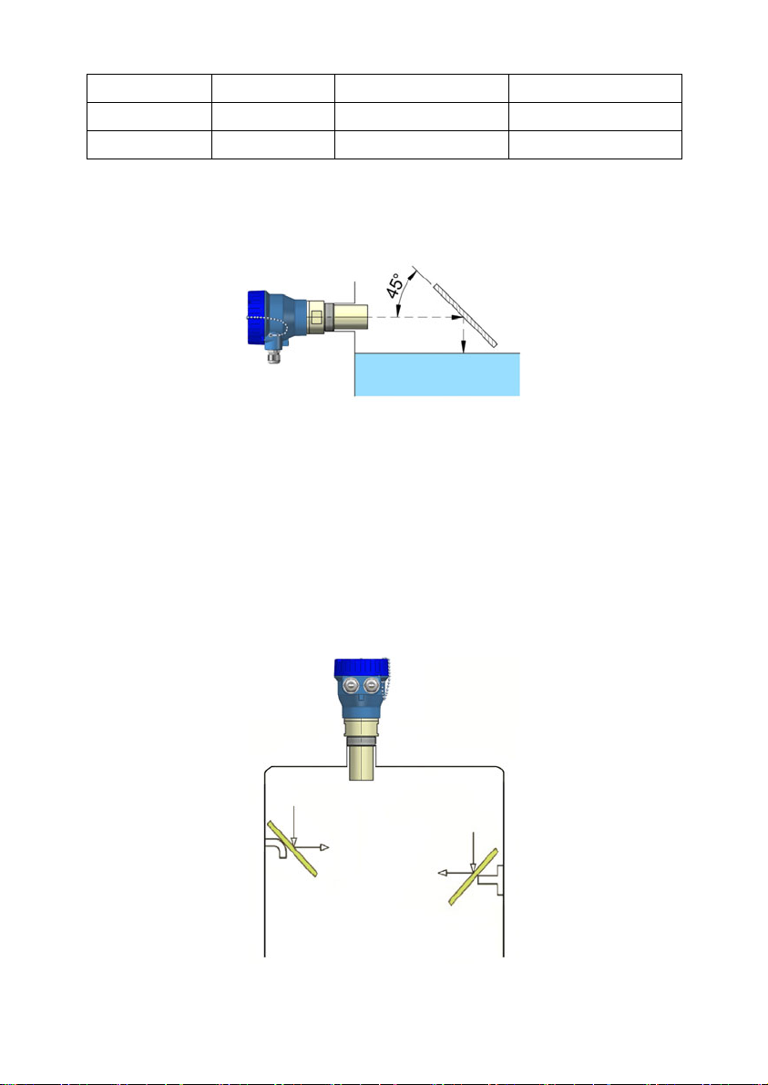
In cases where it is necessary to measure distances shorter than the dead zone, a reflector
can be installed as shown in the figure.
The measured distance will be the addition of the real distance plus the distance between
the transducer and the reflector.
It should be avoided that the product reaches the instrument, since accumulations might
form on the transducer, and that would affect the measurement.
4.2 Obstacles in the vessel
The transmitter must be installed so that the ultrasonic beam cannot find anything on its
path, as this could lead to unwanted echoes and incorrect measures.
In some cases, inclined reflectors can be placed in front of an obstacle, so that the beam in
this region is diverted and the reflected signal does not return to the instrument.

9
4.3 Filling entries
It is not recommended to install the level transmitter in the upper zone of a filling entry,
because the instrument could detect the level of the jet filling instead of the level of the
stored product.
4.4 Foams
Some liquids generate foams when in movement. In vessels with agitators, or in the filling
processes, important layers can be generated that weaken the reflected signal which is
essential for measuring the level.
In a lot of cases the problem of the foam and wave turbulences can be solved by putting a
standpipe.
4.5 Standpipe measurement
It can be appropriated in cases of waves or foam. It is based on placing a tube in the tank so
that the instrument measures the level inside the tube.
The length of the tube depends on the distance that you want to measure, or the minimum
level desired.
The diameter of the tube should be bigger than the threaded connection size of the
instrument (> 2 inches or 50 mm for the LU912 and > 2 1/2" or 65 mm for the LU932).
The standpipe should incorporate a drill top vent grilled hole with a diameter between 5 and
10 mm.
If the standpipe is composed of several sections, it is necessary that the inner wall is free
from defects (welding, edges, etc.) that could be interpreted as a false measurement. In the
same way, if the product is susceptible to leaving adherences or inlaid inside the tube, these
can lead to false readings.
4.6 Temperature
In outdoor installations, the measurement margins can be reduced due to environmental
conditions such as rain or wind, since the ultrasonic signal that travels through the air can be
affected.
It is also recommended to install a protection to avoid direct sunlight on the level transmitter.
The maximum working temperatures are indicated on page 41.

10
5 ELECTRICAL CONNECTION
For the electrical connection, the LU level transmitter is provided of terminal strips. To help in
the wiring of the equipment, the description of the terminals is marked next to each terminal
strip.
For the electrical installation it is recommended to use multiple conductor cables with
individual cable sections in the order of 0.25 to 0.5 mm2in order to make it easier to
connect.
Before starting the installation, check that the cable glands are the right size for the cables to
be used, this will guarantee the instrument will stay watertight. The M16 x 1.5 cable glands
used are for cables with outer diameters between 5 mm and 12 mm.
To connect the cables, peel the outer insulation to free the inner cables. Then pass the
cables through the cable glands and screw down in the corresponding positions of the
terminal strip as indicated in the following point.
Grip carefully the cables with the cable glands to maintain the ingress protection.
Incorrect installation of the cable gland or inadequate cable placement can cause
unrepairable damage to the converter.
5.1 Power supply and analog output wiring
Before starting the installation of the equipment, check that the supply voltage available is
the same as marked on the label of the level transmitter.
Models LU912 and LU932 are two-wire instruments, that is, the equipment is powered
through the current loop.
The positive terminal of the power supply is connected to the position + and the positive
terminal of the load to the position -. The negative terminals of the power supply and the
load are connected together.
Since it is a 2-wire instrument, the supply and signal line is the same. It is recommended to
use a twisted pair wiring or shielded cable to avoid interferences in the current loop.
It is recommended to use a load with a resistance lower than 700 Ω to guarantee a good
performance.

11
Terminal
S1 Source output 1
D1 Drain output 1
S2 Source output 2
D2 Drain output 2
The alarm outputs are connected in the positions D and S of the terminal block.
Outputs are N-channel MOSFET transistor isolated from the rest of the circuit and potential
free.
Example of the connection of the alarm output to a PLC
NOTE: The analog output has protection against reversed polarity. Due to another
protection against overvoltages, if a loop supply voltage with inverted polarity and higher
than 32 V is connected, the equipment may be damaged.
5.2 Alarm outputs wiring

12
6 OPERATION
6.1 Without display module
The instrument allows programming the current loop limits by means of the 4 mA and 20 mA
keys. To do this, the top cover must be remove, previously releasing the DIN913 M3 x 8
safety screw.
The procedure is the following:
Point the equipment to a flat surface and place it at the distance corresponding to 4 mA.
Press the 4 mA button until the led blinks (about 4 seconds).
Then place the equipment at the distance corresponding to 20 mA. Press the 20 mA button
until the LED blinks (about 4 seconds).
From this moment, the level transmitter will transmit the current proportional to the distance
between the two programmed values.
6.2 With display module
The instrument is delivered generally calibrated and programmed to indicate a distance. To
change any configuration parameter, the keyboard can be accessed by removing the top
cover.
LU level transmitters have a graphic display and 4 keys.

13
In the following figure the operation of each key is described.
(Down / Left) To change between
operating screens.
To decrease a digit or to move to the
left digit.
Inside the menus, to shift into the below
element.
(Up) To change between display
screens.
To increase a digit.
Inside the menus, to shift into the
upwards element.
(Enter) To validate a data.
To enter the different menus of the
device.
To exit an informational text.
(Escape) To go back to the previous
menu. To exit a screen without
validating a data.
NOTE: The function of the key (Down / Left) that changes to the left digit is done by
pressing the key for more than one second.
7 MAIN MENU
To access the main menu of the converter, press the key (Enter). The following screen
appears:
The "Installation" option allows to configure the instrument, in order to obtain a correct
indication. It is explained in Chapter 8 of this manual.
The "Programming" option allows to program all parameters of the converter, as explained in
Chapter 9 of this manual.
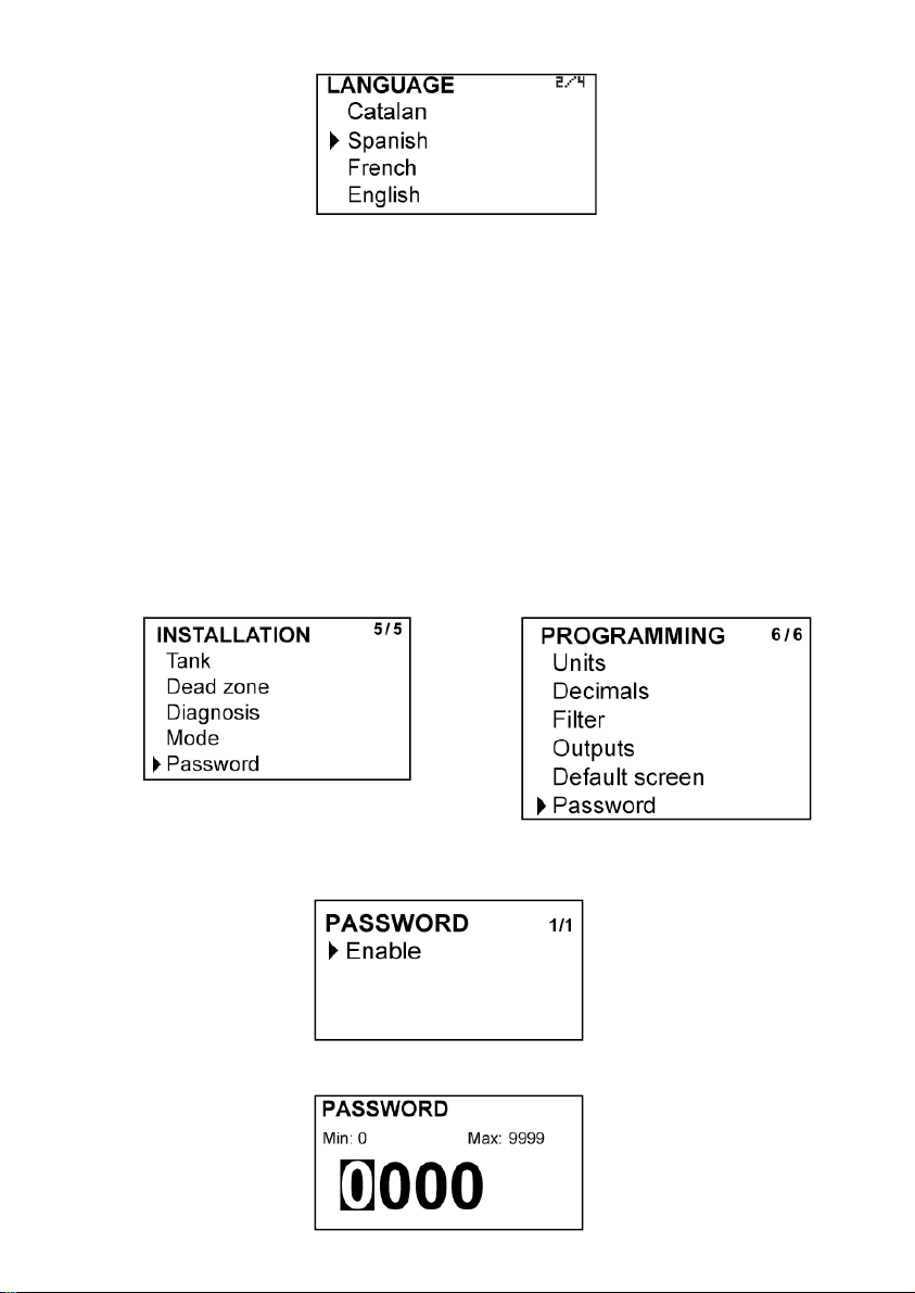
The “Language” option selects the language in which all the menus will be displayed.
14
The options "Serial Number" and "Firmware Version" are informative and are discussed in
Chapters 10 and 11 of this manual.
Finally, the option "Contrast" allows to adjust the contrast of the information on the screen,
to adapt it to the ambient light of each installation.
7.1 Access codes to the menus
It is possible to program a different password for the “Installation” menu and for the
“Programming” menu.
By default, the equipment is factory configured with the passwords disabled.
To change any of these passwords, it is necessary to enter the corresponding menu and
once inside, access the submenu "Password".
To change the access password of
the installation menu, select
"Installation" on the main menu and
then "Password".
To change the access password of
the programming menu, select
"Programming" in the main menu and
then "Password".
When the "Password" option is selected, a screen that indicates the password status for this
menu appears.
Selecting “enable”, the screen to enter the new password appears.
15
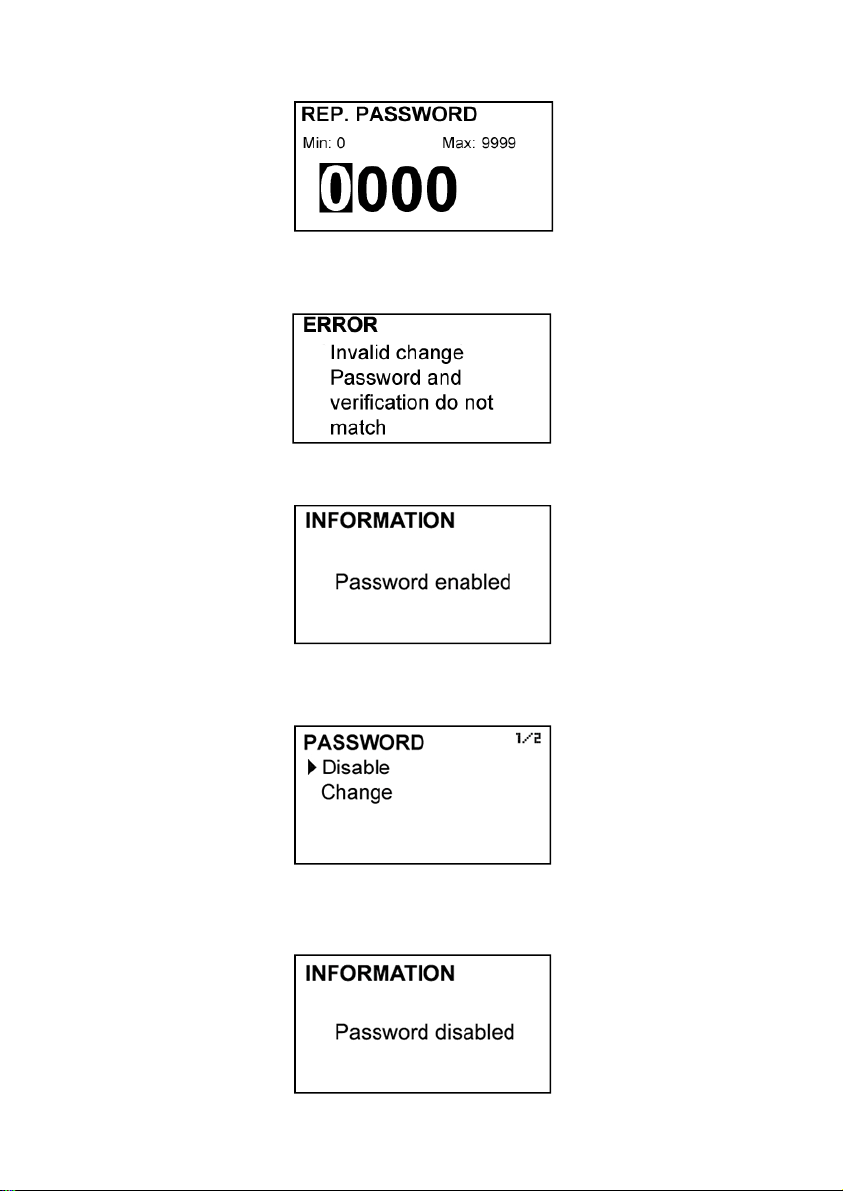
Once entered, the new password is asked again to avoid possible inadvertent error.
If the re-entered password does not match the first one, the following error message
appears and the process should be carried out again.
If both passwords match, the following information message is displayed.
If the password needs to be changed or disabled, the procedure is the same. Once entered
the "Password" menu, the following screen appears:
If “Change” is selected, the equipment will ask for a password again. If “Disable” is selected,
the following message will appear:

16
8 INSTALLATION PARAMETERS
Power on the electronic converter with the voltage indicated on the label.
Press the (Enter) key in order to enter the main menu.
With the keys (Down / Left) and (Up), select “Installation”, and then validate with the key
(Enter).
If the instrument has a password enabled, it must be entered to access the menu. For more
details about the password, see point 7.1 on page 14.
Once in the “Installation” menu, the first screen allows to choose between the different
options.
8.1 Tank
First, a screen appears where the bottom and top distances can be selected. These
distances allow the instrument to indicate measurements in level mode or percentage mode
(see point 9.5 on page 26).

17
8.1.1 Bottom distance
The bottom distance is the distance between the transducer face and the bottom of the
vessel. It allows to calculate el level with respect to that point. This parameter is necessary to
visualize data in level mode or percentage mode, because the instrument takes this distance
as a reference (see point 9.5 on page 26).
The following figure shows the bottom distance. In case of non flat bottom vessels, the
bottom distance should be taken between the end of the instrument, and the desired point
of zero level.
8.1.2 Top distance
This distance is necessary to visualize data in percentage mode (see point 9.5 on page 26).
Bottom
Distance

18
The percentage of filling is calculated given the bottom distance and the top distance (see
points 8.1.1 and 8.1.2 on page 17) , according to the following equation:
When the distance between the product and the sensor is “di”, the visualized percentage is
0%.
When the distance between the product and the sensor is “ds”, the visualized percentage is
100%.
8.2 Dead zone
In this screen the dead zone current and the dead zone length can be chosen.
8.2.1 Dead zone current
When the distance between the instrument and the product surface is shorter than the
minimum measuring distance, that is, when the product is in the dead zone (see section 4.1
on page 7), the instrument can transmit an alarm by means of a value of current out of
range. This value can be either 3.6 mA or 22 mA.
Top
Distance
%
Bottom
Distance
di: bottom distance
ds: top distance

19
When programming this value, the no echo alarm is automatically programmed with the
opposite value.
8.2.2 Dead zone length
In some installations it may be convenient to increase the dead zone value. For example, in
cases of vertical tube measurement.
In this screen the dead zone distance in m can be programmed.
8.3 Diagnosis
It allows to check some parameters of the instrument quickly.
Pressing the key (Enter) when Alarm 1 or Alarm 2 are selected, this output will be activated or
deactivated. When the output is activated, the text is shown as inverse.
Pressing the key (Enter) over 4 mA, the analog output alternates between 4, 8, 12, 16 and
20 mA, which allows to check the analog output adjustment.

20
In all cases the echo intensity is displayed by means of a value between 0 and 100. This
intensity depends on the distance to the target, the type of product where the wave is
reflected and the conditions of installation.
If the distance of the product at the time of verification is longer than half the maximum
measuring distance, it is normal that the intensity has a low value.
In the event that the distance is shorter, if the value of the intensity is low, it may be due to
two reasons:
a) That the product has a high absorption coefficient. This means that an important part of
the wave is absorbed by the product and is not reflected to the instrument. In this case, the
maximum measuring distance will be shorter than specified in the characteristics of the
instrument.
b) That the instrument has not been installed correctly. As the face of the transducer is no
longer parallel to the surface of the product, part of the reflected signal does not return to the
instrument, thus decreasing the intensity of the echo.
8.4 Operating mode
Distance or level can be selected. The reference point to calculate the level is the one
programmed as bottom distance (see point 8.1.1 on page 17).
The instrument will always be working in this mode even if there is a power fail.
Parameters related to the analog output and alarm outputs will be programmed in the
chosen mode.
9 PROGRAMMING PARAMETERS
By the programming parameters the visualization and the outputs of the instrument can be
configured.
Turn on the converter and press (Enter) to enter the main menu. The following screen
appears:
With the keys (Down / Left) and (Up), select “Programming”, and then validate with the key
(Enter).
If the instrument has an enabled password, it must be entered to access the menu. For more
details about the password, see point 7.1 on page 14.
Once in the “Programming” menu, the first screen allows to choose between the different
options.
This manual suits for next models
3
Table of contents
Other Tecfluid Transmitter manuals


Popular Transmitter manuals by other brands


Extech Instruments
Extech Instruments HDV-WTX Informational sheet

WAREMA
WAREMA WMS Wall-mounted transmitter plus Operating and installation instructions

Ritron
Ritron RQT-150 PB user guide

Kvaser
Kvaser Air Bridge Light HS user guide

Simu
Simu LiveIn2 instructions

Sony
Sony Walkman WLA-NWB1K operating instructions


