manuals.online logo
Brands
  1. Home
  2. •
  3. Brands
  4. •
  5. Bosch
  6. •
  7. Transmitter
  8. •
  9. Bosch ISW-EN1210SK User manual

Bosch ISW-EN1210SK User manual

2009 Bosch Security Systems, Inc
130 Perinton Parkway, Fairport, NY 144 0-9199 USA
(800) 289-0096
F01U126808-01-01 1/7
Installation Guide
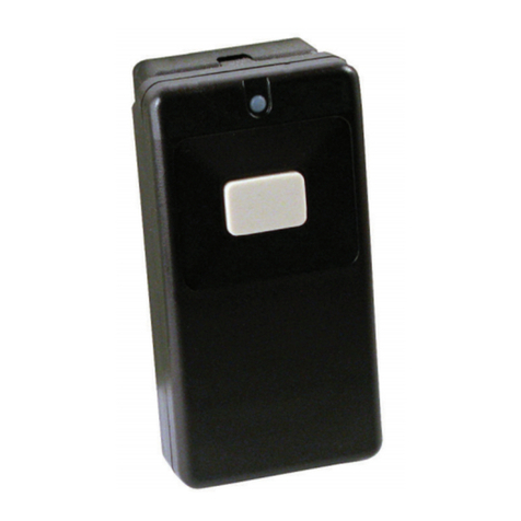
ISW-EN1210SK Installation Guide Universal Survey Transmitter
This item is designed to be used
by professional security technicians.
This product kit is intended for indoor use
.
By following this procedure you can quickly configure the
supplied equipment to perform a site survey. Sections 2.0
through 5.0 list detailed configuration options, features and
detailed startup procedures. Refer to Section 1.0 for a
complete list of survey kit contents.
1. Slide off the battery cover on the back of the ISW-
EN4016SKnsurvey receiver. Refer to Figure 1.
2. Load four AA batteries into the survey receiver.
3. Press the Power button to turn on the survey receiver.
4. Press the Enter button to advance to the main menu.
Figure 1: ISW-EN 016SK Survey Receiver
1 - Transmitter LED display
2 - Power utton
3 - Enter utton
4 - Exit utton
. Select REGISTER POINT on the main menu, and then
press ENTER.
6. Use the small flat-blade screwdriver to press the housing
release tab on either end of the ISW-EN1210SK survey
transmitter. Refer to Figure 2.
7. Separate the housing.
8. On the survey receiver, select POINT 1 on the REGISTER
POINT menu, and then press the Enter button.
9. On the ISW-EN1210SK survey transmitter:
a. Press the RESET button. The survey transmitter
registers with the receiver.
b. Press the On/Off button. The Transmit LED flashes.
Figure 2: ISW-EN1210SK Survey Transmitter
Components
1 - Frequency Band pins
2 - RESET utton
3 - Housing release ta s
4 - Battery
5 - On/Off utton
6 - Transmit LED
10. Place the survey transmitters as close as possible to the
location where you will mount the network coordinator or
receiver.
11. Holding the survey receiver, walk as close as possible to
the first point where you plan to use a transmitter or two-way
device.
Reversing the position of the device and the
high-power repeater makes the survey easier to
perform. This equipment reversal does not affect
the accuracy of the results.
12. On the survey receiver, press the Exit button to return to
the main menu.
13. Select POINT STATUS on the main menu.
14. Select POINT 1 or POINT 2 to view signal information.
Figure 3: Survey Receiver Point Signal Symbols
1 - Signal strength
2 - Transmission sym ol
2009 Bosch Security Systems, Inc
130 Perinton Parkway, Fairport, NY 144 0-9199 USA
(800) 289-0096
F01U126808-01-01 2/7
Installation Guide
1.0 ISW-EN7016 Survey Kit Overview
The ISW-EN7016 survey kit is a portable, easy-to-use
system for conducting site surveys. Site surveys determine
the optimal location for your wireless receivers, high-power
repeaters and devices.
1.1 Measure Signal Strength
The survey kit measures the signal strength of high-power
repeater and device messages to help optimize your system.
The survey kit provides you with two signal-strength
measurements: signal level and signal margin.
• The signal level is the measurement of the overall dB level
of the message.
• The signal margin is the measurement of the dB level of the
message, minus the dB level of any interfering signals. Place
wireless equipment within a facility so that all devices
produce signal margin readings of at least 4 dB.
The signal level and the signal margin are measured in dB.
Because signal strength and signal margin are measured on
a logarithmic scale, the difference between a dB level of 3
(weak) and a dB level of 4 (good) is a much larger difference
than it is on a linear scale.
1.2 ISW-EN7016SW Survey Kit Components
The survey kit is battery-powered for portability.
1.2.1 Survey Kit Component Overview
The following components are included in the survey kit:
• ISW-EN4016SK survey receiver, with belt clip and pendant
accessory
• ISW-EN1223SK survey transmitter, with belt clip and
pendent
accessory for testing the location of pendant transmitters or
two-way devices
• ISW-EN1210SK survey transmitter for testing the location of
all other devices
• Flat-blade screwdriver
• Reversible flat-blade/Phillips® screwdriver
• ISW-EN7016SK Survey Kit Installation Guide
Figure : ISW-EN7016SW Survey Kit Components
1 - ISW-EN7016SW Survey Receiver
2 - ISW-EN1223SK Survey Transmitter
3 - ISW-EN1210SK Survey Transmitter
4 - Accessory compartment
5 - Screwdrivers
1.2.2 Additional Needed Supplies
For the receiver, you must supply:
• 4 fresh AA alkaline batteries, or
• 4 fully-charged AA NiMH rechargeable batteries.
1.2.3 Additional Recommended Supplies
The following supplies are recommended for a site survey:
• Headphones with a 3. mm plug
• A battery charger, if using rechargeable batteries. Bosch
Security Systems, Inc. recommends the Rayovac® PS /PS6
or the Energizer® CH30MNCP-4.
2.0 Configure Survey Transmitter Frequency
Bands
The survey transmitters are designed for use
with the survey kit only. Do not use the survey
transmitters to perform range tests with receivers
other than the ISW-EN4016SK survey receiver.
2.1 Configure the ISW-EN1210SK Survey
Transmitter Frequency Band
1. Use the small flat-blade screwdriver to press the housing
release tab on either end of the ISW-EN1210SK survey
transmitter.
2. Separate the housing.
3. Install the battery. Refer to Figure 5. Ensure that the
positive terminal (+) faces the indicated side of the holder.
Figure 5: ISW-EN1210SK Survey Transmitter
Components
1 - Frequency Band pins
2 - RESET utton
3 - Housing release ta s
4 - Battery
5 - On/Off utton
6 - Transmit LED
4. Select the appropriate frequency band for your geographic
area. Refer to Figure 6 on page 3.
2009 Bosch Security Systems, Inc
130 Perinton Parkway, Fairport, NY 144 0-9199 USA
(800) 289-0096
F01U126808-01-01 3/7
Installation Guide
North American is selected when the jumper is
attached to only one pin. Attach the jumper to only
one pin to prevent losing the jumper when
selecting North America.
Figure 6: ISW-EN1210SK Frequency Band Settings
1 - Australia (915 MHz to 928 MHz)
2 - New Zealand (921 MHz to 928 MHz)
3 - North America (902 MHz to 928 MHz)(default)
. Press the RESET button. Refer to Figure 5 on page 2.
When pressing the RESET button, do not touch
the Frequency Band pins. Touching the Frequency
Band pins while pressing the RESET button can
inadvertently set the transmitter to the wrong
frequency band.
6. Close the housing.
3.0 Configure the Survey Receiver
The survey receiver powers down if no key is
pressed for 30 min, unless the survey receiver
shows one of the POINT STATUS screens. If one
of the POINT STATUS screens shows, the survey
receiver powers down after five hours.
3.1 ISW-EN 016SK Survey Receiver Operation
Figure 7: ISW-EN 016SK Survey Receiver Keypad
1 - Transmitter LED display
2 - Power utton
3 - Up utton
4 - Down utton
5 - Enter utton
6 - Power utton
To operate the survey receiver (refer to Figure 7):
• Press the Up and Down buttons to highlight menu items on
the display screen. Refer to Figure 8.
• Press the Enter button to select highlighted menu items.
• Press the Exit button to return to the previous display
screen.
Figure 8: Survey Receiver Highlighting, Main Menu
1 - Highlighted menu option (underscore on left, uppercase)
2 - Non-highlighted menu option
3 - Battery sym ol
2009 Bosch Security Systems, Inc
130 Perinton Parkway, Fairport, NY 144 0-9199 USA
(800) 289-0096
F01U126808-01-01 4/7
Installation Guide
3.2 ISW-EN 016SK Survey Receiver Configuration
Options
The survey receiver’s main menu shows the model number
and frequency band on the first line. Refer to Figure 8 on
page 3. If the battery is low, the first line shows the battery
symbol as low.
The battery symbol shows on many other screens.
Refer to Ta le 1 for the main menu options.
Table 1: Survey Receiver Main Menu Options
Option Text Function
Point Status View point status.
Register Point Register a point.
Delete Point Delete registered points.
Receiver Setup Configure the receiver.
3.3 Configure the Survey Receiver Frequency Band
1. Press the Power button on the survey receiver keypad to
power on the device. When the receiver information screen
appears, press the Enter button to advance to the main
menu. Refer to Figure 7 on page 3.
2. Press the Down button three times to highlight RECEIVER
SETUP.
3. Press the Enter button to open the RECEIVER SETUP
menu. Refer to Figure 9. Refer to Ta le 2 for the RECEIVER
SETUP menu options.
Figure 9: Survey Receiver Setup Menu
Table 2: Survey Receiver Setup Menu Options
Option
Text
Function
Sounder
Vol
Ctrl
Change the volume for the survey receiver
sounder. The volume is given as a
percentage, with a default of 100%. Press the
Up or Down button to raise or lower the
volume.
Headphone
Vol Ctrl
Change the volume for the optional
headphones. The volume is given as a
percentage, with a default of 100%. Press the
Up or Down button to raise or lower the
volume.
Restore
Defaults
Restore all default receiver configuration
settings, and erase all programmed points..
Freq Band
Setup
Select the appropriate frequency band for your
geographic area. Select the appropriate
frequency band for your
geographic area.
If you restore defaults, all programmed points are
erased. Restoring defaults requires registration of
all points again.
4. Press the Down button three times to highlight FREQ
BAND SETUP.
. Press the Enter button to open the FREQ BAND SETUP
menu.
Figure 10: Survey Receiver Freq Band Setup Menu
6. Use the Up or Down button to select the appropriate
frequency band for your geographic area.
7. Press the Enter button to accept your selection.
8. Press the Exit button repeatedly to return to the main
menu.
Test the transmitter after it is registered with the
system.
To test the transmitter, activate each of the
conditions and ensure an appropriate response.
.0 Register Devices
You must register the survey transmitters and any other
devices you will use to perform a site survey.
The survey receiver can register up to 16 points
(one device per point). Only points that do not
have a device registered to them appear in the
menu. If all points have a device registered to
them, the ALL POINTS ARE REGISTERED
message appears. To register a new point, delete
an existing point and return to the REGISTER
POINT menu.
.1 Register the ISW-EN1210SK Survey Transmitter
1. From the main menu, use the Up or Down button to
highlight REGISTER POINT.
2. Press the Enter button to open the REGISTER POINT
menu. Refer to Figure 11.
Figure 11: Survey Receiver Register Point Menu
3. Use the Up or Down button to highlight POINT 1, and then
press the Enter button to select point 1. A message appears
2009 Bosch Security Systems, Inc
130 Perinton Parkway, Fairport, NY 144 0-9199 USA
(800) 289-0096
F01U126808-01-01 /7
Installation Guide
asking you to press the RESET button.
4. Press the RESET button on the survey transmitter. A
message appears indicating that the registration is
successful. Refer to Figure 12.
Figure 12: Survey Receiver Point Registered Message
.2 Register Devices
1. From the main menu, use the Up or Down button to
highlight REGISTER POINT.
2. Press the Enter button to open the REGISTER POINT
menu. Refer to Figure 11 on page 4.
3. Use the Up or Down button to highlight the desired point,
and then press the Enter button to select that point. A
message appears asking you to press the RESET button.
4. Press the RESET button on the device you wish to
register. A message appears indicating that the registration
completed. Refer to Figure 12 on page .
.3 Register High-power Repeaters
If no high-power repeaters are registered to a point, the
survey receiver uses every high-power repeater in your
system to determine the device RF signal strength for the first
hop (transmit signal from the transmitter to the repeater), and
last hop (transmit signal from the repeater to the receiver),
displaying the results on the point status signal strength
screen.
If you wish to view the first hop results from specific high-
power repeaters, you must register the high-power repeaters
for monitoring. Register high-power repeaters using the steps
for registering other devices. Refer to Section 4.2 Register
Devices.
When high-power repeaters are registered, the last
hop information from a device continues to be
influenced by all repeaters in the system.
If you wish to monitor signal strength from a registered high-
power repeater alone, with no other device, refer to Section
5.0 Perform a Site Survey Using Survey Transmitters, and
choose the point to which you registered the high-power
repeater. Messages repeated by the high-power repeater are
not included in the signal strength information; only
supervision, RESET or restoral and tamper messages count
toward signal strength information.
5.0 Perform a Site Survey Using Survey
Transmitters
The survey kit provides continuous monitoring of the signal
strength of devices and high-power repeaters. The survey
receiver shows device and repeater transmission received
symbols (* and +) on the display screen. The survey receiver
sounder or headphones also indicate the transmission
received information.
When the survey receiver receives a good signal, the
transmission symbols beat once each sec, and the survey kit
beeps accordingly.
To perform the site survey:
1. Prepare a site map, indicating where you plan to mount all
devices and the receiver.
2. Place the survey transmitters where you plan to mount
your network coordinator or receiver.
Place the survey transmitters as close as possible
to the point where you will place the receiver.
3. Open the ISW-EN1210SK survey transmitter housing and
press the On/Off button to begin test transmissions. Refer to
Figure 5 on page 2.
The test transmission continues for four hours,
unless stopped. Press the On/Off button again to
stop the test transmission. Each time the On/Off
button is toggled, a new 4-hr time-out begins.
. Walk with the receiver to the first point of coverage and
place the receiver where you wish to locate the first device.
To ensure an accurate signal reading, place the
receiver as close as possible to the point where
you will mount the device. If mobile devices will be
used, check signals from the most difficult
locations from which users might activate alarms.
6. From the survey receiver main menu, use the Up or Down
button to highlight POINT STATUS.
7. Press the Enter button to open the POINT STATUS menu.
8. Use the Up or Down button to highlight the point number
you wish to use for the device whose location you are testing.
9. Press the Enter button. A point summary appears. Refer to
Figure 13 and Ta le 3 on page 6.
Figure 13: Survey Receiver Point Summary
1 - Point num er
2 - Signal strength
3 - Device transmission sym ol
4 - High-power repeater transmission sym ol
5 - Signal margin
6 - Device attery level
7 - Message num er.
8 - Receive level
2009 Bosch Security Systems, Inc
130 Perinton Parkway, Fairport, NY 144 0-9199 USA
(800) 289-0096
F01U126808-01-01 6/7
Installation Guide
Table 3: Survey Receiver Setup Menu Options
Figure 17
Callout No.
Details
1 The point number you selected.
2 GOOD indicates a sufficient signal margin
(≥4 dB);
WEAK indicates an insufficient margin signal
(<4 dB);
N/S indicates no signal received
(no message received).
3 Flashes approximately once each sec when
the receiver receives a good signal directly
from a selected device. The receiver beeps at
the same rate.
4 Flashes approximately once each sec when
the receiver receives a good signal and when
a high-power repeater passed the signal.
Indicates the overall strength of messages
received from the selected device and
repeaters, shown in decibels (dB).
6 Indicates the signal margin of messages
received from the selected device and
repeaters, shown in decibels (dB).
7 Indicates the total number of messages
received, up to 999.
8 Indicates battery level as OK or LOW.
10. Press the Enter button for more signal information.
Figure 1 : Survey Receiver Message Count Summary
1 - Activation messages received total
2 - Tamper messages received total
3 - Supervisory messages received total
4 - RESET and restoral messages received total
11. Press the Enter button for more signal information.
Figure 15: Survey Receiver Signal Strength Summary
1 - Overall strength of device messages received directly,
shown in deci els (dB)
2 - Signal margin of device messages received directly,
shown in deci els (dB)
3 - Signal margin of first hop device messages received y
high-power repeaters, shown in deci els (dB)
4 - Signal margin of last hop high-power repeater messages
received y the survey kit, shown in deci els (dB)
5 - Overall strength of last hop high-power repeater
messages received y the survey kit, shown in deci els (dB)
6 - Overall strength of first hop device messages received y
high-power repeaters
12. Repeat Steps 2 through 11 for each point on your site
map.
6.0 Perform a Site Survey Without Using
Survey Transmitters
You can use the survey receiver to monitor the signal
strength of any device or high-power repeater in a system.
1. Register the device or high-power repeater you wish to
monitor. Refer to Section 4.2 Register Devices on page and
Section 4.3 Register High-power Repeaters on page .
2. Place the survey receiver where the network coordinator or
receiver is normally located.
3. Activate the device.
4. Monitor signal strength. Refer to Steps 6 through 12 in
Section 5.0 Perform a Site Survey Using Survey
Transmitters.
. When you finish the site survey, press the On/Off buttons
on the ISW-EN1210SK survey transmitters to stop the
transmissions. Then press the Power button on the survey
receiver to turn off the device.
7.0 Specifications
Option Tt Function
Operating Temperature: 0°C to +60°C
Relative Humidity: Up to 90% (non-condensing)
Operating frequency: 91 -928 MHz (Australia),
868 MHz (Europe)
902-928 MHz (USA)
921-928 MHz (New Zealand)
Measurement Accuracy: +/- 2 dB at 2 °C
+/- 3 dB at 0°C - 60°C
Receiver Type: Frequency hopping spread
spectrum
Battery Type/Typical
Battery Life:
ISW-EN4016SK Survey
Receiver:
Eight hours of continuous use,
1. V, AA alkaline or NiMH
ISW1210 Duracell® DL123A,
Panasonic® CR123A, or
approved equivalent
2009 Bosch Security Systems, Inc
130 Perinton Parkway, Fairport, NY 144 0-9199 USA
(800) 289-0096
F01U126808-01-01 7/7
Installation Guide
Trademarks
Energizer® is a registered trademark of Eveready Battery
Company, Inc.
Phillips® is a registered trademark of Phillips Screw
Company in the United States and other countries.
Rayovac® is a registered trademark of Spectrum Brands, its
subsidiaries, and/or its affiliates.
Duracell® is a registered trademark of the Gillette Company,
USA, in the United States and other countries.
Panasonic® is a registered trademark of Matsushita Electric
Industrial Co., Ltd.
SANYO® is a registered trademark of SANYO North America
Corporation.
Renata refers to Renata Batteries, a company of the Swatch
Group.

Other Bosch Transmitter manuals

Bosch ISW-EN1233 User manual

Bosch

Bosch ISW-EN1233 User manual

Bosch S35 User manual

Bosch

Bosch S35 User manual

Bosch CRS-NC-S37L-US User manual

Bosch

Bosch CRS-NC-S37L-US User manual

Bosch ATX-TRM-304T01 User manual

Bosch

Bosch ATX-TRM-304T01 User manual

Bosch CRS-SB-424FI User manual

Bosch

Bosch CRS-SB-424FI User manual

Bosch SE-TRM-433T01 User manual

Bosch

Bosch SE-TRM-433T01 User manual

Bosch RADION RFUN User manual

Bosch

Bosch RADION RFUN User manual

Bosch CRS-NC-S37L User manual

Bosch

Bosch CRS-NC-S37L User manual

Bosch RF3401E User manual

Bosch

Bosch RF3401E User manual

Bosch RFKF-FB User manual

Bosch

Bosch RFKF-FB User manual

Bosch Security Systems SE2 Series Manual

Bosch

Bosch Security Systems SE2 Series Manual

Bosch INTEGRUS User manual

Bosch

Bosch INTEGRUS User manual

Bosch RF3503E User manual

Bosch

Bosch RF3503E User manual

Bosch SEC-3402-304 User manual

Bosch

Bosch SEC-3402-304 User manual

Bosch CRS-NC-S37E-ACC User manual

Bosch

Bosch CRS-NC-S37E-ACC User manual

Bosch ISW-EN1265 User manual

Bosch

Bosch ISW-EN1265 User manual

Bosch ISW-EN1215EOL User manual

Bosch

Bosch ISW-EN1215EOL User manual

Bosch SEC-3402 Series User manual

Bosch

Bosch SEC-3402 Series User manual

Bosch SEC-RFPB60M-433 User manual

Bosch

Bosch SEC-RFPB60M-433 User manual

Bosch ISN-GMX-S1 User manual

Bosch

Bosch ISN-GMX-S1 User manual

Bosch SE88A-90S-304 User manual

Bosch

Bosch SE88A-90S-304 User manual

Bosch SE3401 User manual

Bosch

Bosch SE3401 User manual

Bosch RADION RFUN-A User manual

Bosch

Bosch RADION RFUN-A User manual

Bosch NurseCall N46 User manual

Bosch

Bosch NurseCall N46 User manual

Popular Transmitter manuals by other brands

Neat WALL Famiy Technical handbook

Neat

Neat WALL Famiy Technical handbook

Omega Engineering PHTX-11 Operator's manual

Omega Engineering

Omega Engineering PHTX-11 Operator's manual

SILENTRON 5150 manual

SILENTRON

SILENTRON 5150 manual

CYP CHDBT-1H2CE Operation manual

CYP

CYP CHDBT-1H2CE Operation manual

ISC UC-5770W user guide

ISC

ISC UC-5770W user guide

Racelogic VBOX IPS user guide

Racelogic

Racelogic VBOX IPS user guide

TELECO AUTOMATION Harol EVO manual

TELECO AUTOMATION

TELECO AUTOMATION Harol EVO manual

Audio Ltd. miniTX user guide

Audio Ltd.

Audio Ltd. miniTX user guide

Emerson Rosemount 3101 quick start guide

Emerson

Emerson Rosemount 3101 quick start guide

Crestron DM-TX-201-C Supplemental guide

Crestron

Crestron DM-TX-201-C Supplemental guide

Guntermann & Drunck FIBREVision-USB 2.0 installation guide

Guntermann & Drunck

Guntermann & Drunck FIBREVision-USB 2.0 installation guide

Becker Centronic EC548 Plus Assembly and operating instructions

Becker

Becker Centronic EC548 Plus Assembly and operating instructions

Lightware HDMI-3D-OPT-TX210A quick start guide

Lightware

Lightware HDMI-3D-OPT-TX210A quick start guide

XX.Y BTT009 manual

XX.Y

XX.Y BTT009 manual

Vega VEGABAR S 16 operating instructions

Vega

Vega VEGABAR S 16 operating instructions

Cygnett Mini Wireless FM transmitter quick start guide

Cygnett

Cygnett Mini Wireless FM transmitter quick start guide

Dwyer Instruments DM-2000 Installation and operating instructions

Dwyer Instruments

Dwyer Instruments DM-2000 Installation and operating instructions

Vega VEGABAR 82 operating instructions

Vega

Vega VEGABAR 82 operating instructions

manuals.online logo
manuals.online logoBrands
  • About & Mission
  • Contact us
  • Privacy Policy
  • Terms and Conditions

Copyright 2025 Manuals.Online. All Rights Reserved.