TechNexion TAM-3517 User manual

8/26/2011
TAM-3517 USER’S GUIDE 096 | TechNexion
SOM
TAM-3517 SYSTEM ON MODULE

TAM-3517 USER’S GUIDE 096
TechNexion
2
TAM-3517
TAM-3517 System on Module
and its Baseboards
User’s Guide
Rev 0.96

TAM-3517 USER’S GUIDE 096
TechNexion
3
1Contents
2 Care and maintenance.....................................................................................................................6
2.1 General....................................................................................................................................6
2.2 Regulatory information ............................................................................................................6
3 Introduction ....................................................................................................................................8
4 Get started ......................................................................................................................................9
4.1 First time use Twister baseboard XL (7” LCD)............................................................................9
4.2 First time use Twister baseboard (4.3” LCD) ........................................................................... 13
4.3 Explanation of the TAM-3517W System on Module................................................................ 17
4.5 Explanation of the Twister Baseboard .................................................................................... 19
5 Mechanical Dimensions ................................................................................................................. 22
5.1 TAM-3517 dimensions ........................................................................................................... 22
5.2 Twister dimensions ................................................................................................................ 22
6 Harddisk placement (Twister) ........................................................................................................ 23
7 Downloads and drivers .................................................................................................................. 24
8 Software - Android......................................................................................................................... 25
8.1 Installing an Android image in a Linux environment................................................................ 25
8.1.1 Step1 - Making a SD-card with the image on your computer........................................... 25
8.1.2 Step 2 –Using the SD-card to install an image in the NAND Flash of your Board ............. 27
8.2 Installing an Android image in a Windows environment ......................................................... 29
8.2.1 Step1 - Making a SD-card with the image on your computer........................................... 29
8.2.2 Step 2 –Using the SD-card to install an image in the NAND Flash of your board ............. 35
8.3 Booting from the SD-card....................................................................................................... 36
8.4 How to install an Android application on TechNexion baseboards .......................................... 37
8.5 How to install an android application with an internet connection ......................................... 43
9 Software –Angstrom (Linux).......................................................................................................... 51
9.1 Installing an Angstrom Linux image in a Linux environment.................................................... 51
9.1.1 Step1 - Making a SD-card with the image on your computer........................................... 51
9.1.2 Step 2 –Using the SD-card to install an image in the NAND Flash of your board ............. 53
9.2 Installing an Angstrom Linux image in a Windows environment ............................................. 54
9.2.1 Step1 - Making a SD-card with the image on your computer........................................... 54

TAM-3517 USER’S GUIDE 096
TechNexion
4
9.2.2 Step 2 –Using the SD-card to install an image in the NAND Flash of your board ............. 60
9.3 Booting from the SD-card....................................................................................................... 61
10 Software –Installing with command lines in a Linux environment.............................................. 62
10.1 TechNexion BSP for tam3517 ................................................................................................. 62
10.1.1 SD-card bootable image: ................................................................................................ 62
10.1.2 Installing the image from the SD-card on your board ...................................................... 63
10.1.3 X-loader/u-boot/kernel full source code:........................................................................ 65
10.1.4 Android (Froyo 2.2) full source code: .............................................................................. 66
10.1.5 Angstrom full source code: ............................................................................................. 67
10.1.6 Angstrom prebuild root file system:................................................................................ 68
10.1.7 Android-rowboat-Froyo(2.2) prebuild root file system :.................................................. 68
10.2 How to ................................................................................................................................... 69
10.2.1 After recompiling the system how to place it on a SD card?............................................ 69
10.2.2 How to calibrate the touch screen in Linux ..................................................................... 70
11 Software - Windows CE.............................................................................................................. 71
11.1 Warning................................................................................................................................. 71
11.2 Connecting a null-modem cable ............................................................................................. 71
11.3 Update to Windows Embedded CE6.0 R3 ............................................................................... 74
11.4 Get the BSP ............................................................................................................................ 74
11.4.1 Download the BSP from the web-Site ............................................................................. 74
11.4.2 Install BSP to “Platform Builder for CE 6.0”. .................................................................... 74
11.5 Create a SD card..................................................................................................................... 77
11.6 How to put the WinCE image in the NAND Flash .................................................................... 88
11.6.1 Write the Bootloader and OS image to the NAND Flash. ................................................. 88
11.6.2 Boot from NAND flash. ................................................................................................. 100
11.7 How to change the logo that you see during boot up ........................................................... 108
11.7.1 Preparing the BMP ....................................................................................................... 108
11.7.2 Change the makefile.inc ............................................................................................... 108
11.7.3 Calculated the needed blocks ....................................................................................... 108
11.7.4 Change image-cfg.h...................................................................................................... 110

TAM-3517 USER’S GUIDE 096
TechNexion
5
11.7.5 Compile........................................................................................................................ 110
11.7.6 Put in NAND ................................................................................................................. 110
12 Appendix –Module.................................................................................................................. 111
12.1 Nut to fix TAM-3517 to the baseboard ................................................................................. 111
13 Appendix –Block Diagram........................................................................................................ 112
14 Appendix - Schematics ............................................................................................................. 113
14.1 Twister baseboard schematics.............................................................................................. 113
15 Appendix - Pin outs.................................................................................................................. 124
15.1 Module connector................................................................................................................ 124
15.2 SPI1...................................................................................................................................... 128
15.3 UART 1/UART 3 .................................................................................................................... 129
15.4 Pin header for VGA connector .............................................................................................. 130
15.5 LVDS connector.................................................................................................................... 131
15.6 RS-422/485 connector.......................................................................................................... 133
15.7 GPIO Switch (SW3) ............................................................................................................... 134
15.7.1 Auto Update Procedure................................................................................................ 135
15.8 USB client/host Switch (SW4) ............................................................................................... 136
15.9................................................................................................................................................. 136
15.10 CANBUS ........................................................................................................................... 137
15.11 RS-232 Cable .................................................................................................................... 138
15.12 JTAG Solder Points............................................................................................................ 139

TAM-3517 USER’S GUIDE 096
TechNexion
6
2Care and maintenance
2.1 General
Your device is a product of superior design and craftsmanship and should be treated with care.
The following suggestions will help you.
Keep the device dry. Precipitation, humidity, and all types of liquids or moisture can
contain minerals that will corrode electronic circuits. If your device does get wet, allow it
to dry completely.
Do not use or store the device in dusty, dirty areas. Its moving parts and electronic
components can be damaged.
Do not store the device in hot areas. High temperatures can shorten the life of electronic
devices, damage batteries, and warp or melt certain plastics.
Do not store the device in cold areas. When the device returns to its normal temperature,
moisture can form inside the device and damage electronic circuit boards.
Do not attempt to open the device.
Do not drop, knock, or shake the device. Rough handling can break internal circuit
boards and fine mechanics.
Do not use harsh chemicals, cleaning solvents, or strong detergents to clean the device.
Do not paint the device. Paint can clog the moving parts and prevent proper operation.
Unauthorized modifications or attachments could damage the device and may violate
regulations governing radio devices.
These suggestions apply equally to your device, battery, charger, or any enhancement. If any
device is not working properly, take it to the nearest authorized service facility for service.
2.2 Regulatory information
Disposal of Waste Equipment by Users in Private Household in the European Union
This symbol on the product or on its packaging indicates that this product must
not be disposed of with your other household waste. Instead, it is your
responsibility to dispose of your waste equipment by handing it over to a
designated collection point for the recycling of waste electrical and electronic
equipment. The separate collection and recycling of your waste equipment at the
time of disposal will help to conserve natural resources and ensure that it is
recycled in a manner that protects human health and the environment. For more information
about where you can drop off your waste equipment for recycling, please contact your local city
office, your household waste disposal service or the shop where you purchased the product.
We hereby declare that the product is in compliance with the essential
requirements and other relevant provisions of European Directive 1999/5/EC
(radio equipment and telecommunications terminal equipment Directive).

TAM-3517 USER’S GUIDE 096
TechNexion
7
Federal Communications Commission (FCC) Unintentional emitter per FCC Part 15
This device has been tested and found to comply with the limits for a Class B
digital device, pursuant to Part 15 of the FCC rules. These limits are designed
to provide reasonable protection against harmful interference in a residential
installation. This equipment generates, uses, and can radiate radio frequency
energy and, if not installed and used in accordance with the instructions, may
cause harmful interference to radio or television reception. However, there is no guarantee that
interference will not occur in a particular installation. If this equipment does cause interference
to radio and television reception, which can be determined by turning the equipment off and on,
the user is encouraged to try to correct the interference by one or more of the following
measures:
■ Reorient or relocate the receiving antenna
■ Increase the separation between the equipment and receiver
■ Connect the equipment to an outlet on a different circuit from that to which the receiver is
connected
■ Consult the dealer or an experienced radio/TV technician for help.
WARNING! To reduce the possibility of heat-related injuries or of overheating
the computer, do not place the computer directly on your lap or obstruct the
computer air vents. Use the computer only on a hard, flat surface. Do not allow
another hard surface, such as an adjoining optional printer, or a soft surface,
such as pillows or rugs or clothing, to block airflow. Also, do not allow the AC
adapter to contact the skin or a soft surface, such as pillows or rugs or clothing, during operation.
The computer and the AC adapter comply with the user-accessible surface temperature limits
defined by the International Standard for Safety of Information Technology Equipment (IEC
60950).

TAM-3517 USER’S GUIDE 096
TechNexion
8
3Introduction
The TAM-3517 System on Module (SOM) is a small computer that can be clicked in a
baseboard with several IO’s to form a full computer. Each base board can be developed with
IO’s in different places and with different functions. The Idea behind the product is that anyone
can develop a base board suitable for their needs and just plug in the SOM. This will make the
system very flexible, faster to develop and cheaper than developing a single board solution,
because all the hard work is already completed within the SOM module.
Anybody can buy a TAM-3517 and a Baseboard from our website.
The development kits are meant to test your software on the platform. In the same time you can
develop your own baseboard with the IO’s on the place you need. When your own baseboard is
ready, the module can be plugged into your own baseboard to complete the project.
The TAM-3517 system and its baseboards come in different versions, the user’s guide is meant
as a general guide for all these versions. Pictures and details of the device can differ from the
actual purchased product. All specifications are subject to change without notice.
One can always check our website (www.technexion.com ) for more details, to download this
user guide or to see other information.

TAM-3517 USER’S GUIDE 096
TechNexion
9
4Get started
4.1 First time use Twister baseboard XL (7” LCD)
This guide describes how to put the TAM-3517W module and the Twister interface board
together, how to connect the LCD and power up the board.
Figure 1: Step 1 - After clicking the module onto the board. Use a small Philips screwdriver and
fix the module on the interface board. By doing so you guarantee the connection is firm and
solid.
Connecting the 7” LCD touch panel (XL version) to the Twister interface board should be done
by following the following steps.
Please make sure to gently open/close the connector and handle the FPC connector at the LCD
and the LCD panel itself with care.
White dot (pin 1)
Step 1: fix module

TAM-3517 USER’S GUIDE 096
TechNexion
10
(Note: RS-232 serial console cable might need a gender changer when connected to, for
example, a null-modem. One can also reverse the connected cable)
Figure 2: Step 2a - Pull the connector, on the topside of the PCB, sideward carefully open with
your nail. (NOTE: the board has different connector options; please check if it is a “slide” or “turn”
connector before opening. Handling the connector wrong will lead to damage)
Figure 3: Step 2b - Insert the LCD panel FPC. And push the connector sideways to close

TAM-3517 USER’S GUIDE 096
TechNexion
11
Figure 4: Step 3a - Connect the RS-232 serial console cable as on the picture above. (Note:
RS-232 serial console cable might need a gender changer when connected to, for example, a
null-modem. One can also reverse the connected cable)
Step 3b: Use the USB cable and connect to a USB or computer system. The cable should only
be inserted into the USB port shown above. Connect the adapter to power the Twister interface
board and the LCD. (The power cord is not included in the pack; please get one with a plug that
fits your local power outlet)
Step 4: Use the spacers (stand offs) for a stable placement, to prevent shorts on conducting
surfaces, protect the components on the bottom and to allow free airflow for cooling.
Step 5: for better WIFI reception connect the antenna to the U.FL (IPEX) connector on the TAM-
3517W module.
White dot (pin 1)
Step 4: spacers
Step 5: WIFI

TAM-3517 USER’S GUIDE 096
TechNexion
12
Warning! Without the below setting the screen might show unexpected results.
Check if your dip switch (SW3) is set as follows:
3
2
1
OFF
OFF
ON
7” panel

TAM-3517 USER’S GUIDE 096
TechNexion
13
4.2 First time use Twister baseboard (4.3” LCD)
Connecting the 4.3” LCD touch panel (Standard version) to the Twister interface board should
be done by following the following steps.
Please make sure to gently open/close the connector and handle the FPC connector at the LCD
and the LCD panel itself with care.
Figure 5: Step 2a - Turn the connector at the bottom side of the Twister baseboard about 90
degrees open with your nail. (NOTE: the board has different connector options; please check if
it is a “slide” or “turn” connector before opening. Handling the connector wrong will lead to
damage)

TAM-3517 USER’S GUIDE 096
TechNexion
14
Figure 6-7: Step 2b - Insert the LCD panel FPC. And turn the connector down to close

TAM-3517 USER’S GUIDE 096
TechNexion
15
Figure 8: Step 3a - Connect the RS-232 serial console cable as on the picture above. (Note:
RS-232 serial console cable might need a gender changer when connected to, for example, a
null-modem. One can also reverse the connected cable)
Step 3b: Use the USB cable and connect to a USB or computer system. The cable should only
be inserted into the USB port shown above. Connect the adapter to power the Twister interface
board and the LCD. (The power cord is not included in the pack; please get one with a plug that
fits your local power outlet)
Step 4: Use the spacers (stand offs) for a stable placement, to prevent shorts on conducting
surfaces, protect the components on the bottom and to allow free airflow for cooling.
Step 5: for better WIFI reception connect the antenna to the U.FL (IPEX) connector on the TAM-
3517W module.
White dot (pin 1)
Step 4: spacers
Step 5: WIFI

TAM-3517 USER’S GUIDE 096
TechNexion
16
Warning! Without the below setting the screen might show unexpected results.
Check if your dip switch (SW3) is set as follows:
3
2
1
OFF
OFF
OFF
4.3” panel

TAM-3517 USER’S GUIDE 096
TechNexion
17
4.3 Explanation of the TAM-3517W System on Module
Figure 9
Front view
1CPU
2Memory
3NAND Flash
4EEPROM
5Wireless LAN 802.11b/g by SDIO MMC1 interface with IPEX U.FL connector (TAM-
3517W = Wireless)
6LAN PHY
7USB PHY
8LED 0: Wireless
1
B1
2
3
2
4
5
6
7
8
9
10

TAM-3517 USER’S GUIDE 096
TechNexion
19
4.5 Explanation of the Twister Baseboard
B1
1
2
3
4
6
7
8
9
10
11
12
13
15
16
17
18
19
20
21
22
23
24
25
26
27
28
29
30

TAM-3517 USER’S GUIDE 096
TechNexion
20
B1
Connector to the TAM-3517 CPU module (DDR2 SO-DIMM 200 pin SMT, standard, H:6.5 mm,
e.g. Foxconn AS0A426-N6SN-4F or Tyco 5-1746530-4)
1
connector for 7” LCD panel
2
Connector for 4 wire touch panel of LCD panel
3
GPIO Switch (marked with SW3)
4
Front panel connector
6
Power / reset button
7
USB (10) Switch between host and client
8
RS-232 Switch between UART1 and UART3
9
Pin header for RS-232
10
USB OTG
11
LEDs
31
32
33
34
Other manuals for TAM-3517
1
Table of contents
Other TechNexion Control Unit manuals
TechNexion
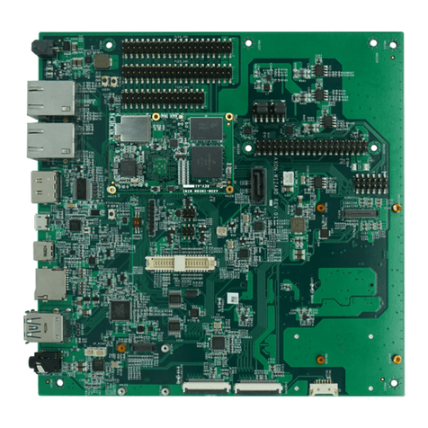
TechNexion PICO-WIZARD-IMX8M-MINI User manual
TechNexion
TechNexion PICO-IMX8M User manual
TechNexion
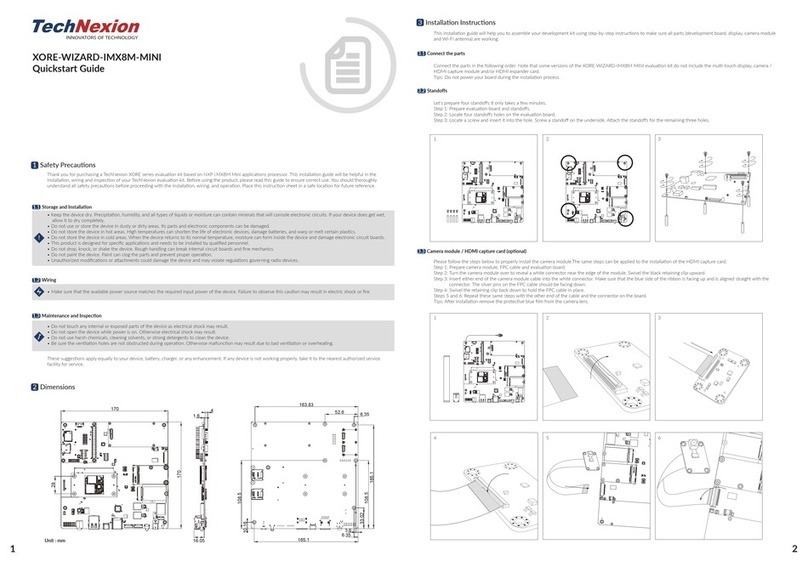
TechNexion XORE-WIZARD-IMX8M-MINI User manual
TechNexion
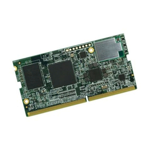
TechNexion FLEX-IMX8M-Mini User manual
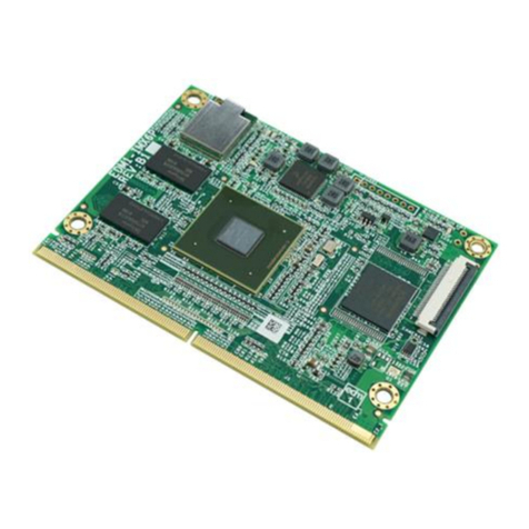
TechNexion
TechNexion EDM1-IMX6 User manual

TechNexion
TechNexion PIXI-9377 User manual
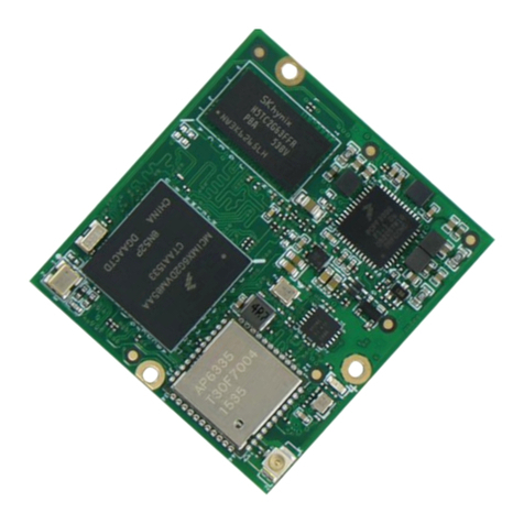
TechNexion
TechNexion PICO-IMX6UL-EMMC User manual
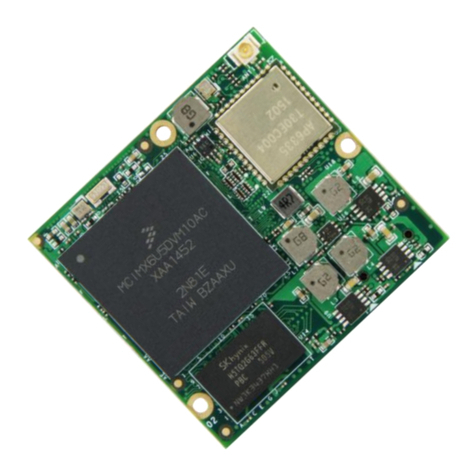
TechNexion
TechNexion PICO-IMX6 User manual
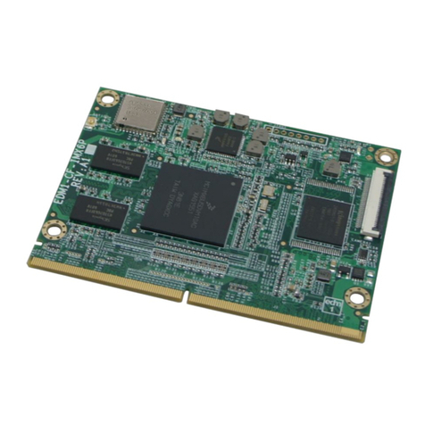
TechNexion
TechNexion EDM1-IMX6PLUS User manual


