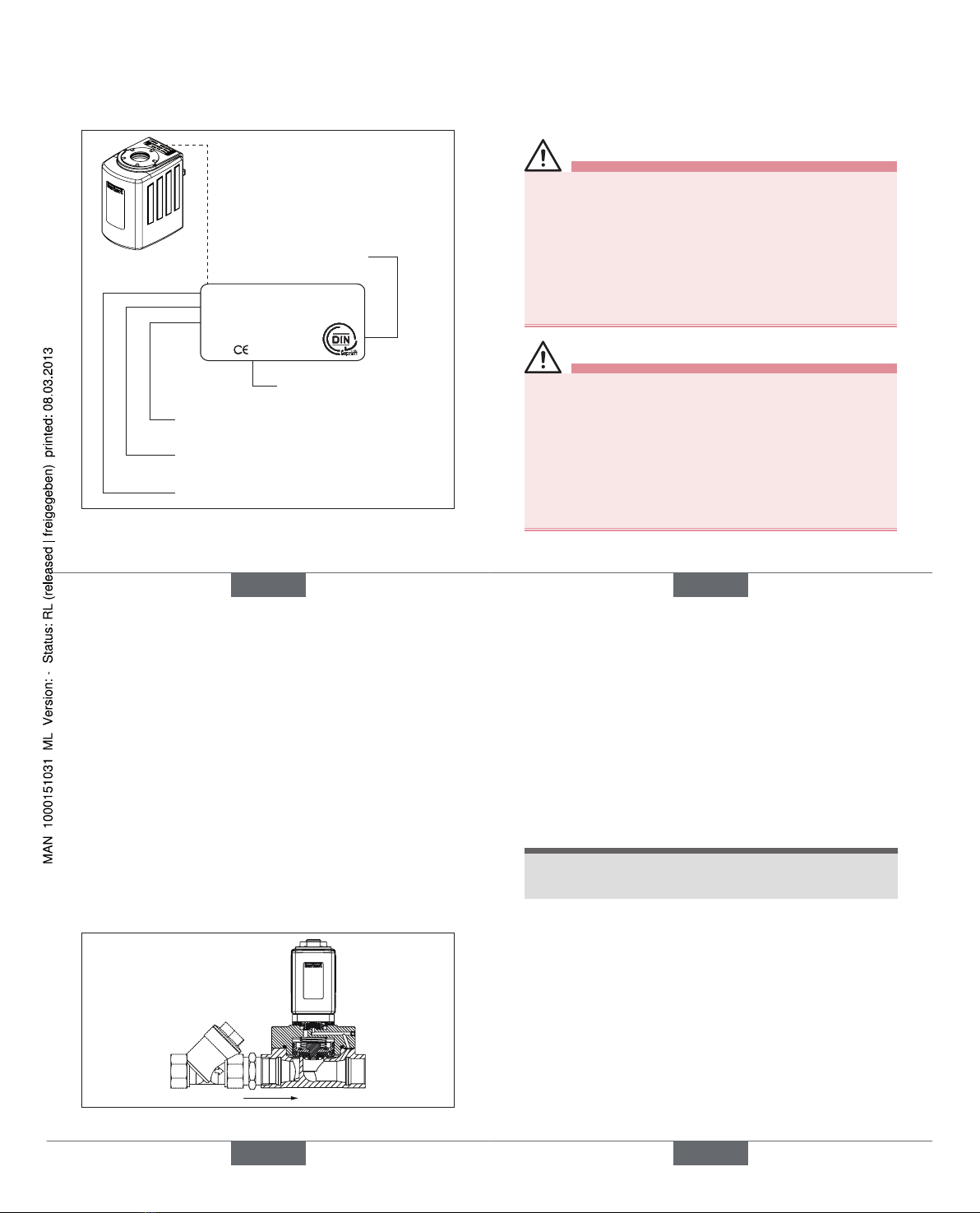
Burkert 5406 User manual

www.burkert.com
We reserve the right to make
technical changes without notice.
Technische Änderungen
vorbehalten.
Sous resérve de modification
techniques.
© 2011 Bürkert Werke GmbH
Operating Instructions
1102/00_EU-ml_00805777
Type 5406 / DN 6, DN 13, DN 20
Safety shut-off device
TÜV certified according to DIN EN ISO 23553-1
Operating Instructions
Bedienungsanleitung
Manuel d‘utilisation
2
1. OPERATING INSTRUCTIONS
The operating instructions describe the entire life cycle of the
device. Keep these instructions in a location which is easily
accessible to every user and make these instructions available
to every new owner of the device.
The operating instructions contain important safety
information!
Failure to observe these instructions may result in hazardous
situations.
• The operating instructions must be read and understood.
english
3
2. SYMBOLS
In these instructions, the following symbols are used.
DANGER!
Warns of an immediate danger!
• Failure to observe the warning may result in a fatal or
serious injury.
WARNING!
Warns of a potentially dangerous situation!
• Failure to observe the warning may result in a serious or
fatal injury.
CAUTION!
Warns of a possible danger!
• Failure to observe the warning may result in medium or
minor injury.
NOTE!
Warns of damage to property!
Important tips and recommendations.
→designates a procedure which you must carry out.
english

4
3. AUTHORIZED USE
Non-intended use of the safety shut-off device Type
5406 may be a hazard to people, nearby equipment
and the environment.
• The device, which controls the supply of heating oil to a
burner, was specifically designed for furnaces.
• Use according to the authorized data, operating and
service conditions specified in the contract documents
and operating instructions. These are described in the
chapter on „Technical Data“.
• Bürkert valves must not be used in combination with
valves from other manufacturers.
• Correct transportation, storage and installation, and
careful use and maintenance are essential for reliable
and faultless operation.
• The valve 5406 may be used exclusively in the flow of
a firing plant.
english
5
3.1. Restrictions
If exporting the system/device, observe any existing
restrictions.
3.2. Predictable misuse
• Do not put any loads on the housing (e.g. by placing objects
on it or standing on it).
• Do not make any external modifications to the device
housings. Do not paint the housing parts or screws.
• The safety shut-off device is designed for heating oils DIN
51603 Part 1-6 with viscosity 1.6 - 76 cST. The use of
other media is not permitted without a prior agreement with
the Bürkert sales office.
english
6
4. BASIC SAFETY
INSTRUCTIONS
These safety instructions do not make allowance for any
• contingencies and events which may arise during the
installation, operation and maintenance of the devices.
• local safety regulations – the operator is responsible for
observing these regulations, also with reference to the
installation personnel.
DANGER!
Danger – high pressure!
• Before loosening the lines and valves, turn off the pres-
sure and vent the lines.
Risk of electric shock!
• Before reaching into the system, switch off the power
supply and secure to prevent reactivation.
• Observe applicable accident prevention and safety
regulations for electrical equipment!
Risk of burns due to hot surface of the device!
• Do not touch the device with bare hands.
english
7
WARNING!
Risk of injury due to malfunction of valves with alter-
nating current (AC).
Sticking core causes coil to overheat, resulting in a
malfunction.
• Monitor process to ensure function is in perfect work-
ing order!
WARNING!
Risk of injury due to impaired function after external
fire.
• After an external fire, check the equipment and safety
shut-off device.
• If there is visible damage, replace safety shut-off device!
WARNING!
Risk of short-circuit/escape of media through leaking
screw joints.
• Ensure seals are seated correctly!
• Carefully screw together coil and device socket or valve
and connection plate!
english
Type 5406

8
General Hazardous Situations.
To prevent injuries:
• Ensure that the system cannot be activated unintentionally.
• Installation and maintenance work may only be carried
out by authorized technicians with the appropriate tools.
• After an interruption in the power supply, ensure that the
process is restarted in a defined or controlled manner.
• The device may be installed and operated only when in
a perfect condition and in consideration of the operat-
ing instructions for the valve and furnace.
• The general rules of technology must be observed for
application planning and operation of the device.
Failure to observe this operating manual and its
operating instructions as well as unauthorized tam-
pering with the device release us from any liability
and also invalidate the warranty covering the device
and accessories!
english
9
5. GENERAL INFORMATION
5.1. Contact address
Germany
Bürkert Fluid Control Systems
Sales Center
Christian-Bürkert-Str. 13-17
D-74653 Ingelfingen
Tel. + 49 (0) 7940 - 10 91 111
Fax + 49 (0) 7940 - 10 91 448
E-mail: [email protected]
International
Contact addresses can be found on the final pages of the
printed operating instructions.
And also on the internet at: www.burkert.com
5.2. Warranty
The warranty is only valid if the device is used as intended in
accordance with the specified application conditions.
5.3. Information on the Internet
The operating instructions and data sheets for Type 5406 be
found on the Internet at: www.burkert.com
english
10
6. TECHNICAL DATA
The following values are indicated on the type label:
• Ambient and medium temperature, voltage 1)
(tolerance ±10%), kind of current, pressure
1)
If used in combination with a return flow valve connected electrically
in series, the voltage value on the type label is half the respective
mains voltage.
Materials
Housing: DN 6, DN 13: Brass
DN 20: Stainless steel
Seat seal: PTFE (E)
Housing seal: FKM (F)
Coil jacket: Epoxy
Media
Heating oils DIN 51603 Part 1-6 at a viscosity
1.6 ... 76 cST (other media by arrangement with the
Bürkert sales office)
Operating principle 2/2-way valve
A (NC)
P
A
Protection class: IP65 nach EN 60529 mit
zugelassener Gerätesteckdose nach
DIN 175301-803
english
11
6.1. Type label
6.1.1. Standard type label
Housing material
Seal material
Orifice
Id. Number
Voltage, Frequency, Output
Connecting thread, Nominal
pressure, Protection class
5406 NC 6,0 EF MS
XXXXXXX W1X LU
110-120V 50Hz 20W
00YYYYYYY
G 1/4 P
N 1
-
30 bar IP65
Operating principle
Type
Customer article number (optional)
Fig. 1: Location and description of the type label
english
Type 5406

12
6.1.2. Type label approval
(depending on version)
Register number
Permitted ambient temperature
Max. permitted medium temperature
T med. Max. 160°C
T Umg. -15°C bis 60°C
Reg.Nr. XXXXX
0036
Inspection body
Certification mark
Fig. 2: Location and description of the additional plate
english
13
7. INSTALLATION
7.1. Safety instructions
DANGER!
Risk of injury from high pressure in the system!
• Before loosening the lines and valves, turn off the
pressure and vent the lines.
Risk of injury due to electrical shock!
• Before reaching into the system , switch off the power
supply and secure to prevent reactivation!
• Observe applicable accident prevention and safety
regulations for electrical equipment!
WARNING!
Risk of injury from improper installation!
• Installation may only be carried out by authorized tech-
nicians with the appropriate tools!
Risk of injury from unintentional activation of the
system and an uncontrolled restart!
• Secure system from unintentional activation.
• Following assembly, ensure a controlled restart.
english
14
7.2. Before Installation
Installation position:
Installation can be in any position.
Preferably: Drive at the top.
→To ensure that the safety shut-off device functions reliably,
check the pipelines for dirt and clean if required.
Dirt filter:
• For orifice DN 6:
A dirt filter is installed in the valve inlet.
• For orifices DN 13 and DN 20:
A dirt filter (≤ 500 μm) must be installed before the valve
inlet (see Fig. 3).
Fig. 3: Installation of the dirt filter
english
15
7.3. Installation
→Clean pipelines.
→Only use new seals.
→Hold the device with a suitable tool (open-end wrench)
on the housing and screw into the pipeline.
→Observe direction of flow:
From 1 → 2 (from P → A) or direction of arrow on the
housing.
NOTE!
Caution risk of breakage!
• Do not use the coil as a lifting arm.
english
Type 5406

16
7.4. Connecting the device socket
to the power supply
WARNING!
Risk of injury due to electrical shock!
• Before reaching into the system, switch off the electri-
cal power supply and secure to prevent reactivation!
• Observe applicable accident prevention and safety
regulations for electrical equipment!
If the protective conductor contact between the coil and
housing is missing, there is danger of electrical shock!
• Always connect protective conductor.
• Check electrical continuity between coil and housing.
Seal
max. 1 Nm
Approved device socket
e.g. Type 2508 or similar
Fig. 4: Connecting the device socket to the power supply
english
17
8. MAINTENANCE AND REPAIRS
8.1. Safety instructions
DANGER!
Risk of injury from high pressure in the equipment!
• Before loosening the lines and valves, turn off the
pressure and vent the lines.
Risk of injury due to electrical shock!
• Before reaching into the system , switch off the power
supply and secure to prevent reactivation!
• Observe applicable accident prevention and safety
regulations for electrical equipment!
Risk of injury from improper repair work!
• Maintenance may only be carried out by authorized
technicians with the appropriate tools!
Risk of injury from unintentional activation of the
system and an uncontrolled restart!
• Secure system from unintentional activation.
• Following maintenance, ensure a controlled restart.
english
18
8.2. Installation of coil
WARNING!
Escaping medium!
When a sticking nut is loosened, medium may escape.
• Do not tighten sticking nut any further.
Electric shock!
If the protective conductor contact between the coil and
housing is missing, there is danger of electrical shock!
• During installation insert the plastic ring (optional) into
the housing journal. The plastic ring must not project
over the octagonal nipple.
• Check protective conductor contact after installing the
coil.
Overheating, risk of fire!
Connection of the coil without pre-assembled valve will
result in overheating and destroy the coil.
• Connect the coil with pre-assembled valve only.
english
19
Observe torque!
15 Nm
O-ring
Nut
Plastic ring
(optional)
Fig. 5: Coil installation
The rotational position of the coil on the valve housing is arbitrary.
english
Type 5406

20
9. MALFUNCTIONS
If malfunctions occur, check whether:
→the device has been installed according to the instruc-
tions (correct direction of installation),
→the connection has been made properly,
→the device is not damaged,
→all screws have been tightened,
→the voltage and pressure have been switched on,
→the pipelines are clean.
If the magnet is not attracting
Possible causes:
• Short circuit or coil interrupted,
• Core or core area dirty.
After occurrence of an external fire
• After an external fire, check the equipment and safety
shut-off device.
• If there is visible damage, replace safety shut-off device.
english
21
10. SPARE PARTS
CAUTION!
Risk of injury and/or damage by the use of incorrect
parts!
Incorrect accessories and unsuitable spare parts may cause
injuries and damage the device and the surrounding area.
• Use original accessories and original spare parts from
Bürkert only.
Fittings set
Coil set
Nut Nut and coil set can
be ordered com-
pletely by quoting
the identification
number of the
device (see type
label).
Fittings set on
request.
Fig. 6: Spare parts
english
22
11. PACKAGING, TRANSPORT,
STORAGE, DISPOSAL
NOTE!
Transport damages!
Inadequately protected equipment may be damaged
during transport.
• During transportation protect the device against wet
and dirt in shock-resistant packaging.
• Avoid exceeding or dropping below the allowable
storage temperature.
Incorrect storage may damage the device.
• Store the device in a dry and dust-free location!
• Storage temperature. -30 … +80 °C.
Damage to the environment caused by device compo-
nents contaminated with media.
• Dispose of the device and packaging in an environ-
mentally friendly manner.
• Observe applicable regulations on disposal and the
environment.
• Observe national waste disposal regulations.
english
Type 5406

www.burkert.com
We reserve the right to make
technical changes without notice.
Technische Änderungen
vorbehalten.
Sous resérve de modification
techniques.
© 2011 Bürkert Werke GmbH
Operating Instructions
1102/00_EU-ml_00805777
Typ 5406 / DN 6, DN 13, DN 20
Sicherheitsabsperreinrichtung
TÜV-geprüft nach DIN EN ISO 23553-1
Bedienungsanleitung
Deutsch
24
1. DIE BEDIENUNGSANLEITUNG
Die Bedienungsanleitung beschreibt den gesamten Lebens-
zyklus des Gerätes. Bewahren Sie diese Anleitung so auf,
dass sie für jeden Benutzer gut zugänglich ist und jedem
neuen Eigentümer des Gerätes wieder zur Verfügung steht.
Die Bedienungsanleitung enthält wichtige Informa-
tionen zur Sicherheit!
Das Nichtbeachten dieser Hinweise kann zu gefährlichen
Situationen führen.
• Die Bedienungsanleitung muss gelesen und verstanden
werden.
deutsch
25
2. DARSTELLUNGSMITTEL
In dieser Anleitung werden folgende Darstellungsmittel
verwendet.
GEFAHR!
Warnt vor einer unmittelbaren Gefahr!
• Bei Nichtbeachtung sind Tod oder schwere Verletzun-
gen die Folge.
WARNUNG!
Warnt vor einer möglicherweise gefährlichen Situation!
• Bei Nichtbeachtung können schwere Verletzungen oder
Tod die Folge sein.
VORSICHT!
Warnt vor einer möglichen Gefährdung!
• Nichtbeachtung kann mittelschwere oder leichte Verlet-
zungen zur Folge haben.
HINWEIS!
Warnt vor Sachschäden!
Wichtige Tipps und Empfehlungen.
→markiert einen Arbeitsschritt den Sie ausführen müssen.
deutsch

26
3. BESTIMMUNGSGEMÄSSE
VERWENDUNG
Bei nicht bestimmungsgemäßem Einsatz der Sicher-
heitsabsperreinrichtung Typ 5406 können Gefahren für
Personen, Anlagen in der Umgebung und die Umwelt
entstehen.
• Das Gerät wurde speziell für Feuerungsanlagen konzipiert
und steuert die Versorgung eines Brenners mit Heizöl.
• Für den Einsatz die in den Vertragsdokumenten und der
Bedienungsanleitung spezifizierten zulässigen Daten,
Betriebs- und Einsatzbedingungen beachten. Diese sind
im Kapitel „Technische Daten“ beschrieben.
• Ventile von Bürkert dürfen nicht mit Ventilen anderer
Hersteller kombiniert werden.
• Voraussetzungen für den sicheren und einwandfreien
Betrieb sind sachgemäßer Transport, sachgemäße
Lagerung und Installation sowie sorgfältige Bedienung
und Instandhaltung.
• Das Ventil 5406 darf ausschließlich im Vorlauf einer
Feuerungsanlage verwendet werden.
deutsch
27
3.1. Beschränkungen
Beachten Sie bei der Ausfuhr des Systems/Gerätes gege-
benenfalls bestehende Beschränkungen.
3.2. Vorhersehbarer Fehlgebrauch
• Das Gehäuse nicht mechanisch belasten (z. B. durch
Ablage von Gegenständen oder als Trittstufe).
• Keine äußerlichen Veränderungen an den Gerätegehäusen
vornehmen. Gehäuseteile und Schrauben nicht lackieren.
• Die Sicherheitsabsperreinrichtung ist für Heizöle DIN
51603 Teil 1-6 mit Viskosität 1,6 ... 76 cST konzipiert. Der
Einsatz anderer Medien ist nur nach Absprache mit der
Bürkert-Vertriebsniederlassung zulässig.
deutsch
28
4. GRUNDLEGENDE
SICHERHEITSHINWEISE
Diese Sicherheitshinweise berücksichtigen keine:
• Zufälligkeiten und Ereignisse, die bei Montage, Betrieb
und Wartung der Geräte auftreten können.
• Ortsbezogenen Sicherheitsbestimmungen, für deren
Einhaltung, auch in Bezug auf das Montagepersonal, der
Betreiber verantwortlich ist.
GEFAHR!
Gefahr durch hohen Druck!
• Vor dem Lösen von Leitungen oder Ventilen den Druck
abschalten und Leitungen entlasten.
Gefahr durch elektrische Spannung!
• Vor Eingriffen in das Gerät oder die Anlage, Spannung
abschalten und vor Wiedereinschalten sichern!
• Die geltenden Unfallverhütungs- und Sicherheitsbe-
stimmungen für elektrische Geräte beachten!
Verbrennungsgefahr durch heiße Geräteoberfläche!
• Das Gerät nicht mit bloßen Händen berühren.
deutsch
29
WARNUNG!
Verletzungsgefahr durch Funktionsausfall bei Ventilen
mit Wechselspannung (AC).
Festsitzender Kern bewirkt Spulenüberhitzung, die zu
Funktionsausfall führt.
• Arbeitsprozess auf einwandfreie Funktion überwachen!
WARNUNG!
Verletzungsgefahr durch Funktionsbeeinträchtigungen
nach externem Brand.
• Nach einem externen Brand, Anlage und Sicherheitsab-
sperreinrichtung überprüfen.
• Bei sichtbaren Schäden, Sicherheitsabsperreinrichtung
austauschen!
WARNUNG!
Kurzschlussgefahr/Austritt von Medium durch
undichte Verschraubungen.
• Auf einwandfreien Sitz der Dichtungen achten!
• Spule und Gerätesteckdose bzw. Ventil und Anschluss-
platte sorgfältig verschrauben!
deutsch
Typ 5406

30
Allgemeine Gefahrensituationen.
Zum Schutz vor Verletzungen ist zu beachten:
• Dass die Anlage nicht unbeabsichtigt betätigt werden
kann.
• Installations- und Instandhaltungsarbeiten dürfen nur von
autorisiertem Fachpersonal mit geeignetem Werkzeug
ausgeführt werden.
• Nach einer Unterbrechung der elektrischen Versorgung
ist ein definierter oder kontrollierter Wiederanlauf des
Prozesses zu gewährleisten.
• Das Gerät darf nur in einwandfreiem Zustand und unter
Beachtung der Bedienungsanleitung für das Ventil und
der Feuerungsanlage betrieben werden.
• Für die Einsatzplanung und den Betrieb des Gerätes
müssen die allgemeinen Regeln der Technik eingehalten
werden.
Bei Nichtbeachtung dieser Bedienungsanleitung
und ihrer Hinweise sowie bei unzulässigen Eingriffen
in das Gerät entfällt jegliche Haftung unsererseits,
ebenso erlischt die Gewährleistung auf Geräte und
Zubehörteile!
deutsch
31
5. ALLGEMEINE HINWEISE
5.1. Kontaktadressen
Deutschland
Bürkert Fluid Control Systems
Sales Center
Christian-Bürkert-Str. 13-17
D-74653 Ingelfingen
Tel. + 49 (0) 7940 - 10 91 111
Fax + 49 (0) 7940 - 10 91 448
E-mail: [email protected]
International
Die Kontaktadressen finden Sie auf den letzten Seiten der
gedruckten Bedienungsanleitung.
Außerdem im Internet unter: www.burkert.com
5.2. Gewährleistung
Voraussetzung für die Gewährleistung ist der bestimmungs-
gemäße Gebrauch des Gerätes unter Beachtung der spezi-
fizierten Einsatzbedingungen.
5.3. Informationen im Internet
Bedienungsanleitungen und Datenblätter zum Typ 5406
finden Sie im Internet unter: www.buerkert.de
deutsch
32
6. TECHNISCHE DATEN
Folgende Werte sind auf dem Typenschild angegeben:
• Umgebungs- und Mediumstemperatur,
Spannung 1) (Toleranz ±10 %), Stromart, Druck
1)
Bei Verwendung in Kombination mit einem Rücklaufventil in elektri-
scher Reihenschaltung ist der Spannungswert auf dem Typenschild
die Hälfte der jeweiligen Netzspannung.
Werkstoffe
Gehäuse: DN 6, DN 13: Messing
DN 20: Edelstahl
Sitzdichtung: PTFE (E)
Gehäusedichtung: FKM (F)
Spulenummantelung: Epoxid
Medien
Heizöle DIN 51603 Teil 1-6 mit Viskosität 1,6 ... 76 cST
(weitere Medien nach Absprache mit der Bürkert-Ver-
triebsniederlassung)
Wirkungsweise 2/2-Wege Ventil
A (NC)
P
A
Schutzart IP65 nach EN 60529 mit zugelassener
Gerätesteckdose nach DIN 175301-803
deutsch
33
6.1. Typenschild
6.1.1. Typenschild Standard
Gehäusewerkstoff
Dichtwerkstoff
Nennweite
Identnummer
Spannung, Frequenz, Leistung
Anschlussgewinde, Nenndruck,
Schutzart
5406 NC 6,0 EF MS
XXXXXXX W1X LU
110-120V 50Hz 20W
00YYYYYYY
G 1/4 P
N 1
-
30 bar IP65
Wirkungsweise
Typ
Kunden-Artikelnummer (optional)
Bild 1: Lage und Beschreibung des Typenschildes
deutsch
Typ 5406

34
6.1.2. Typenschild Zulassung
(je nach Ausführung)
Registernummer
Zulässige Umgebungstemperatur
Max. zulässige Mediumstemperatur
T med. Max. 160°C
T Umg. -15°C bis 60°C
Reg.Nr. XXXXX
0036
Überwachungsstelle
Zertifizierungszeichen
Bild 2: Lage und Beschreibung des Zusatzschildes
deutsch
35
7. MONTAGE
7.1. Sicherheitshinweise
GEFAHR!
Verletzungsgefahr durch hohen Druck in der Anlage!
• Vor dem Lösen von Leitungen oder Ventilen den Druck
abschalten und Leitungen entlasten.
Verletzungsgefahr durch Stromschlag!
• Vor Eingriffen in das Gerät oder die Anlage, Spannung
abschalten und vor Wiedereinschalten sichern!
• Die geltenden Unfallverhütungs- und Sicherheitsbestim-
mungen für elektrische Geräte beachten!
WARNUNG!
Verletzungsgefahr bei unsachgemäßer Montage!
• Die Montage darf nur autorisiertes Fachpersonal mit
geeignetem Werkzeug durchführen!
Verletzungsgefahr durch ungewolltes Einschalten
der Anlage und unkontrollierten Wiederanlauf!
• Anlage vor unbeabsichtigtem Betätigen sichern.
• Nach der Montage einen kontrollierten Wiederanlauf
gewährleisten.
deutsch
36
7.2. Vor dem Einbau
Einbaulage:
Die Einbaulage ist beliebig.
Vorzugsweise: Antrieb oben.
→Für die sichere Funktion der Sicherheitsabsperrein-
richtung die Rohrleitungen auf Verschmutzungen über-
prüfen und gegebenenfalls reinigen.
Schmutzfilter:
• Für Nennweite DN 6:
Im Ventileingang ist ein Schmutzfilter eingebaut.
• Für Nennweiten DN 13 und DN 20:
Vor dem Ventileingang muss ein Schmutzfilter
(≤ 500 μm) eingebaut werden (siehe Bild 3).
Bild 3: Einbau des Schmutzfilters
deutsch
37
7.3. Einbau
→Rohrleitungen reinigen.
→Nur neue Dichtungen verwenden.
→Das Gerät mit geeignetem Werkzeug (Gabelschlüssel)
am Gehäuse festhalten und die Rohrleitung einschrauben.
→Durchflussrichtung beachten:
Von 1 → 2 (von P → A) oder Pfeilrichtung auf dem
Gehäuse.
HINWEIS!
Vorsicht Bruchgefahr!
• Die Spule darf nicht als Hebelarm benutzt werden.
deutsch
Typ 5406

38
7.4. Elektrischer Anschluss der
Gerätesteckdose
WARNUNG!
Verletzungsgefahr durch Stromschlag!
• Vor Eingriffen in das System die elektrische Spannung
abschalten und vor Wiedereinschalten sichern!
• Die geltenden Unfallverhütungs- und Sicherheitsbestim-
mungen für elektrische Geräte beachten!
Bei fehlendem Schutzleiterkontakt zwischen Spule und
Gehäuse besteht die Gefahr des Stromschlags!
• Schutzleiter immer anschließen.
• Elektrischer Durchgang zwischen Spule und Gehäuse
prüfen.
Dichtung
max. 1 Nm
Zugelassene
Gerätesteckdose z. B. Typ
2508 oder andere
Bild 4: Elektrischer Anschluss der Gerätesteckdose
deutsch
39
8. WARTUNG UND REPARATUR
8.1. Sicherheitshinweise
GEFAHR!
Verletzungsgefahr durch hohen Druck in der Anlage!
• Vor dem Lösen von Leitungen oder Ventilen den Druck
abschalten und Leitungen entlasten.
Verletzungsgefahr durch Stromschlag!
• Vor Eingriffen in das Gerät oder die Anlage, Spannung
abschalten und vor Wiedereinschalten sichern!
• Die geltenden Unfallverhütungs- und Sicherheitsbestim-
mungen für elektrische Geräte beachten!
Verletzungsgefahr bei unsachgemäßen
Reparaturarbeiten!
• Die Wartung darf nur autorisiertes Fachpersonal mit
geeignetem Werkzeug durchführen!
Verletzungsgefahr durch ungewolltes Einschalten der
Anlage und unkontrollierten Wiederanlauf!
• Anlage vor unbeabsichtigtem Betätigen sichern.
• Nach der Wartung einen kontrollierten Wiederanlauf
gewährleisten.
deutsch
40
8.2. Spulenmontage
WARNUNG!
Mediumsaustritt!
Beim Lösen einer festsitzenden Mutter kann Medium
austreten.
• Festsitzende Mutter nicht weiterdrehen.
Stromschlag!
Bei fehlendem Schutzleiterkontakt zwischen Spule und
Gehäuse besteht die Gefahr des Stromschlags!
• Der Kunststoffring (optional) muss bei der Montage in
den Gehäusezapfen eintauchen. Er darf nicht über den
Achtkantnippel herausragen.
• Schutzleiterkontakt nach der Spulenmontage prüfen.
Überhitzung, Brandgefahr!
Der Anschluss der Spule ohne vormontiertes Ventil führt
zur Überhitzung und zerstört die Spule.
• Spule nur mit vormontiertem Ventil anschließen.
deutsch
41
Drehmoment beachten!
15 Nm
O-Ring
Mutter
Kunststoffring
(optional)
Bild 5: Spulenmontage
Die Drehposition der Spule auf dem Ventilgehäuse ist beliebig.
deutsch
Typ 5406

42
9. STÖRUNGEN
Überprüfen Sie bei Störungen ob:
→das Gerät vorschriftsmäßig installiert ist (richtige
Einbaurichtung),
→der Anschluss ordnungsgemäß ausgeführt ist,
→das Gerät nicht beschädigt ist,
→alle Schrauben fest angezogen sind,
→Spannung und Druck anliegen,
→die Rohrleitungen schmutzfrei sind.
Falls der Magnet nicht anzieht
Mögliche Ursache:
• Kurzschluss oder Spulenunterbrechung,
• Kern oder Kernraum verschmutzt.
Nach Auftreten eines externen Brandes
• Nach einem externen Brand, Anlage und Sicherheitsab-
sperreinrichtung überprüfen.
• Bei sichtbaren Schäden, Sicherheitsabsperreinrichtung
austauschen.
deutsch
43
10. ERSATZTEILE
VORSICHT!
Verletzungsgefahr, Sachschäden durch falsche Teile!
Falsches Zubehör und ungeeignete Ersatzteile können Ver-
letzungen und Schäden am Gerät und dessen Umgebung
verursachen.
• Nur Originalzubehör sowie Originalersatzteile der Firma
Bürkert verwenden.
Armaturen-Set
Spulen-Set
Mutter Mutter und
Spulen-Set können
komplett unter der
Identnummer des
Gerätes bestellt
werden (siehe
Typenschild).
Armaturen-Set auf
Anfrage.
Bild 6: Ersatzteile
deutsch
44
11. VERPACKUNG, TRANSPORT,
LAGERUNG, ENTSORGUNG
HINWEIS!
Transportschäden!
Unzureichend geschützte Geräte können durch den
Transport beschädigt werden.
• Gerät vor Nässe und Schmutz geschützt in einer stoß-
festen Verpackung transportieren.
• Eine Über- bzw. Unterschreitung der zulässigen Lager-
temperatur vermeiden.
Falsche Lagerung kann Schäden am Gerät verursachen!
• Gerät trocken und staubfrei lagern!
• Lagertemperatur. -30 … +80 °C.
Umweltschäden durch von Medien kontaminierte
Geräteteile.
• Das Gerät und die Verpackung umweltgerecht entsorgen.
• Geltende Entsorgungsvorschriften und Umweltbestim-
mungen einhalten.
• Die nationalen Abfallbeseitigungsvorschriften
beachten.
deutsch
Typ 5406

www.burkert.com
We reserve the right to make
technical changes without notice.
Technische Änderungen
vorbehalten.
Sous resérve de modification
techniques.
© 2011 Bürkert Werke GmbH
Operating Instructions
1102/00_EU-ml_00805777
Type 5406 / DN 6, DN 13, DN 20
Dispositif d‘arrêt de sécurité
Contrôle TÜV selon DIN EN ISO 23553-1
Manuel d‘utilisation
Français
46
1. LES INSTRUCTIONS DE
SERVICE
Les instructions de service décrivent le cycle de vie complet
de l‘appareil. Conservez ces instructions de sorte qu‘elles
soient accessibles à tout utilisateur et à disposition de tout
nouveau propriétaire.
Les instructions de service contiennent des informa-
tions importantes sur la sécurité !
Le non-respect de ces consignes peut entraîner des
situations dangereuses.
• Les instructions de service doivent être lues et comprises.
français
47
2. SYMBOLES
Les moyens de représentation suivants sont utilisés dans
les présentes instructions de service.
DANGER !
Met en garde contre un danger imminent !
• Le non-respect peut entraîner la mort ou de graves
blessures.
AVERTISSEMENT !
Met en garde contre une situation éventuellement
dangereuse !
• Le non-respect peut entraîner de graves blessures ou la mort.
ATTENTION !
Met en garde contre un risque possible !
• Le non-respect peut entraîner des blessures légères ou
de moyenne gravité.
REMARQUE !
Met en garde contre des dommages matériels !
Conseils et recommandations importants.
→identifie une opération que vous devez effectuer.
français

48
3. UTILISATION CONFORME
L’utilisation non conforme du dispositif d’arrêt de
sécurité type 5406 peut présenter des dangers pour les
personnes, les installations proches et l’environnement.
• L’appareil a été conçu spécialement pour les installations
de chauffe. Il commande l’alimentation d’un brûleur avec
fioul.
• Lors de l’utilisation, il convient de respecter les données
et conditions d’utilisation et d’exploitation admissibles
spécifiées dans les instructions de service et dans les
documents contractuels. Celles-ci sont décrites au
chapitre „Caractéristiques techniques“.
• Les vannes de Bürkert ne doivent pas être combinées
avec des vannes d’un autre constructeur.
• Les conditions pour l’utilisation sûre et parfaite sont un
transport, un stockage et une installation dans les règles
ainsi qu’une parfaite utilisation et maintenance.
• La vanne 5406 doit être utilisée uniquement dans le
départ d’une installation de chauffage.
français
49
3.1. Limitations
Lors de l’exportation du système/de l’appareil, veuillez res-
pecter les limitations éventuelles existantes.
3.2. Mauvaise utilisation prévisible
• Ne soumettez pas le corps à des contraintes mécaniques
(par ex. pour déposer des objets ou en l’utilisant comme
marche).
• N’apportez pas de modifications à l’extérieur du corps de
l’appareil. Ne laquez pas les pièces du corps et les vis.
• Le dispositif d’arrêt de sécurité est conçu pour les mazouts
de type DIN 51603 parties 1-6 avec une viscosité de
1,6 ... 76 cST. L’utilisation d’autres fluides est uniquement
possible avec accord de la filiale de distribution Bürkert.
français
50
4. CONSIGNES DE SÉCURITÉ
FONDAMENTALES
Ces consignes de sécurité ne tiennent pas compte
• des hasards et des événements pouvant survenir lors
du montage, de l’exploitation et de la maintenance des
appareils.
• des prescriptions de sécurité locales que l’exploitant
est tenu de faire respecter par le personnel chargé du
montage.
DANGER !
Danger dû à la haute pression !
• Avant de desserrer les conduites et les vannes, cou-
pez la pression et purgez l'air des conduites.
Danger présenté par la tension électrique !
• Avant d'intervenir dans le système, coupez la tension et
empêchez toute remise sous tension par inadvertance.
• Veuillez respecter les réglementations en vigueur pour
les appareils électriques en matière de prévention des
accidents ainsi qu'en matière de sécurité !
Risque de brûlures dû à des surfaces d'appareils
brûlantes !
• Ne pas toucher l'appareil à mains nues.
français
51
AVERTISSEMENT !
Risque de blessure dû à une panne des vannes avec
tension alternative (AC).
Un noyau bloqué provoque la surchauffe de la bobine et
donc une panne.
• Surveiller le bon fonctionnement du processus de travail !
AVERTISSEMENT !
Risque de blessure dû aux restrictions de fonction-
nement après un incendie externe.
• Après un incendie externe, contrôler l'installation et le
dispositif d'arrêt de sécurité.
• En cas de dommages visibles, remplacer le dispositif
d'arrêt de sécurité !
AVERTISSEMENT !
Risque de court-circuit/de sortie du fluide en pré-
sence de vissages non étanches.
• Veiller à l'installation correcte des joints !
• Visser prudemment la bobine et la prise de l'appareil ou
la vanne et la plaque de connexion !
français
Type 5406

52
Situations dangereuses d'ordre général.
Pour prévenir les blessures, respectez ce qui suit :
• L'installation ne peut pas être actionnée par inadvertance.
• Les travaux d'installation et de maintenance doivent être
effectués uniquement par des techniciens qualifiés et
habilités disposant de l'outillage approprié.
• Après une interruption de l'alimentation électrique, un
redémarrage défini ou contrôlé du process doit être
garanti.
• L'appareil doit être monté et utilisé uniquement en parfait
état et en respectant les instructions de service pour la
vanne et l'installation de chauffe.
• Les règles générales de la technique sont d'application
pour planifier l'utilisation et utiliser l'appareil.
Le non-respect de ces instructions de service avec
ses consignes ainsi que les interventions non auto-
risées sur l'appareil excluent toute responsabilité
de notre part et entraînent la nullité de la garantie
légale concernant les appareils et les accessoires !
français
53
5. INDICATIONS GÉNÉRALES
5.1. Adresse
Allemagne
Bürkert Fluid Control Systems
Sales Center
Christian-Bürkert-Str. 13-17
D-74653 Ingelfingen
Tel. + 49 (0) 7940 - 10 91 111
Fax + 49 (0) 7940 - 10 91 448
E-mail: [email protected]
International
Les adresses se trouvent aux dernières pages des instruc-
tions de service imprimées.
Egalement sur internet sous : www.burkert.com
5.2. Garantie légale
La condition pour bénéficier de la garantie légale est l’utili-
sation conforme de l’appareil dans le respect des conditions
d’utilisation spécifiées.
5.3. Informations sur Internet
Vous trouverez les instructions de service et les fiches
techniques concernant le type 5406 sur Internet sous :
www.buerkert.fr
français
54
6. CARACTÉRISTIQUES
TECHNIQUES
Les valeurs suivantes sont indiquées sur la plaque
signalétique :
• Température ambiante et du fluide, tension 1)
(Tolérance ±10 %), type de courant, pression
1)
En cas d’utilisation en association avec une vanne de retour dans
un montage en série électrique, la valeur de tension sur la plaque
signalétique est égale à la moitié de la tension de réseau.
Matériaux
Boîtier : DN 6, DN 13 : Laiton
DN 20 : Acier inoxydable
Joint de siège : PTFE (E)
Joint du boîtier : FKM (F)
Enveloppe de la bobine : Epoxid
Fluides
Fiouls DIN 51603 parties 1-6 avec une viscosité
1,6 ... 76 cST (autres fluides après accord de la filiale de
distribution Bürkert)
Mode de fonctionnement vanne 2/2 voies
A (NC)
P
A
Type de protection IP65 selon EN 60529 avec fiche de l’ap-
pareil autorisée selon DIN 175301-803
français
55
6.1. Plaque signalétique
6.1.1. Plaque signalétique standard
Matériau du boîtier
Matériau du joint
Diamètre nominal
N° d’identification
Tension, fréquence, puissance
Filetage de raccordement, pression
nominale, type de protection
5406 NC 6,0 EF MS
XXXXXXX W1X LU
110-120V 50Hz 20W
00YYYYYYY
G 1/4 P
N 1
-
30 bar IP65
Fonction
Type
Numéro d’article client (en option)
Fig. 1 : Emplacement et description de la plaque signalétique
français
Type 5406

56
6.1.2. Plaque signalétique
homologation (selon la version)
Numéro d’enregistrement
Température ambiante admissible
Température de fluide maximale admissible
T med. Max. 160°C
T Umg. -15°C bis 60°C
Reg.Nr. XXXXX
0036
Organisme de surveillance
Symbole de certification
Fig. 2 : Emplacement et description de la plaque supplémentaire
français
57
7. MONTAGE
7.1. Consignes de sécurité
DANGER !
Risque de blessures dû à la présence de haute
pression dans l'installation !
• Avant de desserrer les conduites et les vannes, cou-
pez la pression et purgez l'air des conduites.
Risque de choc électrique !
• Avant d'intervenir dans le système , coupez la tension et
empêchez toute remise sous tension par inadvertance !
• Veuillez respecter les réglementations en vigueur pour
les appareils électriques en matière de prévention des
accidents ainsi qu'en matière de sécurité !
AVERTISSEMENT !
Risque de blessures dû à un montage non conforme !
• Le montage doit être effectué uniquement par un person-
nel qualifié et habilité disposant de l'outillage approprié !
Risque de blessures dû à la mise en marche involon-
taire de l'installation et le redémarrage non contrôlé !
• Empêchez tout actionnement involontaire de l'installation.
• Garantissez un redémarrage contrôlé après le montage.
français
58
7.2. Avant le montage
Position de montage :
Position de montage indifférente.
De préférence avec l’entraînement en haut.
→Pour garantir le fonctionnement fiable du dispositif d’arrêt
de sécurité, contrôler la présence d’encrassement dans
les tuyauteries et les nettoyer si nécessaire.
Filtre à impuretés :
• Pour diamètre nominal DN 6 :
Un filtre à impuretés est intégré dans l’entrée de la
vanne.
• Pour les diamètres nominaux DN 13 et DN 20 :
Un filtre à impuretés (≤ 500 µm) doit être intégré en
amont de l’entrée de la vanne (voir Fig. 3).
Fig. 3 : Montage du filtre à impuretés
français
59
7.3. Montage
→Nettoyer les tuyauteries.
→N’utiliser que des joints neufs.
→Maintenez l’appareil sur le boîtier à l’aide d’un outil
approprié (clé à fourche) et vissez-le dans la tuyauterie.
→Respecter le sens du débit :
De 1 → 2 (de P → A) ou sens de la flèche sur le corps.
REMARQUE !
Attention risque de rupture !
• La bobine ne doit pas être utilisée comme levier.
français
Type 5406

60
7.4. Raccordement électrique de la
prise d’appareil
AVERTISSEMENT !
Risque de choc électrique !
• Avant d'intervenir dans le système, coupez la tension et
empêchez toute remise sous tension par inadvertance !
• Veuillez respecter les réglementations en vigueur pour
les appareils électriques en matière de prévention des
accidents ainsi qu'en matière de sécurité !
Il y a risque de choc électrique en l'absence d'un contact
du conducteur de protection entre la bobine et le boîtier !
• Raccordez toujours le conducteur de protection.
• Contrôlez le passage du courant entre la bobine et le boîtier.
Joint
max. 1 Nm
Prise de l’appareil homo-
loguée, par ex. type 2508
ou autre
Fig. 4 : Raccordement électrique de la prise d’appareil
français
61
8. MAINTENANCE, RÉPARATION
8.1. Consignes de sécurité
DANGER !
Risque de blessures dû à la présence de haute
pression dans l'installation !
• Avant de desserrer les conduites et les vannes, cou-
pez la pression et purgez l'air des conduites.
Risque de choc électrique !
• Avant d'intervenir dans le système , coupez la tension et
empêchez toute remise sous tension par inadvertance !
• Veuillez respecter les réglementations en vigueur pour
les appareils électriques en matière de prévention des
accidents ainsi qu'en matière de sécurité !
Risque de blessures dû à des travaux de réparation
non conformes !
• La maintenance doit être effectuée uniquement par un
personnel qualifié et habilité disposant de l'outillage
approprié !
Risque de blessures dû à la mise en marche involon-
taire de l'installation et le redémarrage non contrôlé !
• Empêchez tout actionnement involontaire de l'installation.
• Garantissez un redémarrage contrôlé après la
maintenance.
français
62
8.2. Montage de la bobine
AVERTISSEMENT !
Sortie de fluide !
Lors du desserrage d'un écrou fixe, du fluide peut s'échapper.
• Ne pas continuer de tourner l'écrou fixe.
Choc électrique !
Il y a risque de choc électrique en l'absence d'un contact
du conducteur de protection entre la bobine et le boîtier !
• La bague en plastique (en option) doit pénétrer dans la
cheville de l'appareil lors du montage. Elle ne doit pas
dépasser du nipple octogonal.
• Contrôler le contact du conducteur de protection
après montage de la bobine.
Surchauffe, risque d'incendie !
Le raccordement de la bobine sans vanne en amont
entraîne la surchauffe et la destruction de la bobine.
• Raccorder la bobine uniquement avec la vanne
prémontée.
français
63
Respecter le couple de serrage !
15 Nm
Joint torique
Écrou
Bague en
plastique (en
option)
Fig. 5 : Montage de la bobine
La position de rotation de la bobine sur le boîtier de la vanne
est indifférente.
français
Type 5406

64
9. PANNES
En cas d’incidents, vérifiez si :
→l’appareil est installé dans les règles (sens de montage
correct),
→le raccordement a été correctement effectué,
→l’appareil n’est pas endommagé,
→toutes les vis sont bien serrées,
→la tension et la pression sont disponibles,
→les tuyauteries sont propres.
Si l’aimant n’attire pas
Cause possible :
• Court-circuit ou coupure de la bobine,
• Noyau ou cœur encrassé.
Après un incendie externe
• Après un incendie externe, contrôler l’installation et le
dispositif d’arrêt de sécurité.
• En cas de dommages visibles, remplacer le dispositif
d’arrêt de sécurité.
français
65
10. PIÈCES DE RECHANGE
ATTENTION !
Risque de blessures, de dommages matériels dus à
de mauvaises pièces !
De mauvais accessoires ou des pièces de rechange
inadaptées peuvent provoquer des blessures et endom-
mager l'appareil ou son environnement.
• Utiliser uniquement des accessoires et des pièces de
rechange d'origine de la société Bürkert.
Jeu de
robinetteries
Jeu de bobines
Écrou Les écrous et le jeu
complet de bobines
peuvent être com-
mandés sous le
numéro d’identification
de l’appareil (voir
plaque signalétique).
Jeu de robinetteries
sur demande.
Fig. 6 : Pièces de rechange
français
66
11. EMBALLAGE, TRANSPORT,
STOCKAGE, ÉLIMINATION
REMARQUE !
Dommages dus au transport !
Les appareils insuffisamment protégés peuvent être
endommagés pendant le transport.
• Transportez l'appareil à l'abri de l'humidité et des impu-
retés et dans un emballage résistant aux chocs.
• Évitez le dépassement vers le haut ou le bas de la tem-
pérature de stockage admissible.
Un mauvais stockage peut endommager l'appareil.
• Stockez l'appareil au sec et à l'abri des poussières !
• Température de stockage : -30 – +80 °C.
Dommages à l'environnement causés par des pièces
d'appareil contaminées par des fluides.
• Eliminez l'appareil et l'emballage dans le respect de
l'environnement.
• Respectez les prescriptions en matière d'élimination des
déchets et de protection de l'environnement en vigueur.
• Respectez les prescriptions nationales en matière
d'élimination des déchets.
français
Type 5406
Other manuals for 5406
1
Table of contents
Languages:
Other Burkert Control Unit manuals

Burkert
Burkert 0121 User manual

Burkert
Burkert 0330 User manual

Burkert
Burkert 2100 series Guide

Burkert
Burkert 6211 EV User manual

Burkert
Burkert 6020 User manual

Burkert
Burkert 5470 User manual

Burkert
Burkert 6013 User manual

Burkert
Burkert PTB 00 ATEX 2202 X User manual

Burkert
Burkert 6603 User manual

Burkert
Burkert 2030 User manual

Burkert
Burkert 3360 User manual

Burkert
Burkert 5281 Series User manual

Burkert
Burkert 2031 User manual

Burkert
Burkert 3320 User manual

Burkert
Burkert 6510 User manual

Burkert
Burkert 2712 Series User manual

Burkert
Burkert 5282 User manual

Burkert
Burkert 6144 User manual

Burkert
Burkert 0283 User manual

Burkert
Burkert 6027 User manual