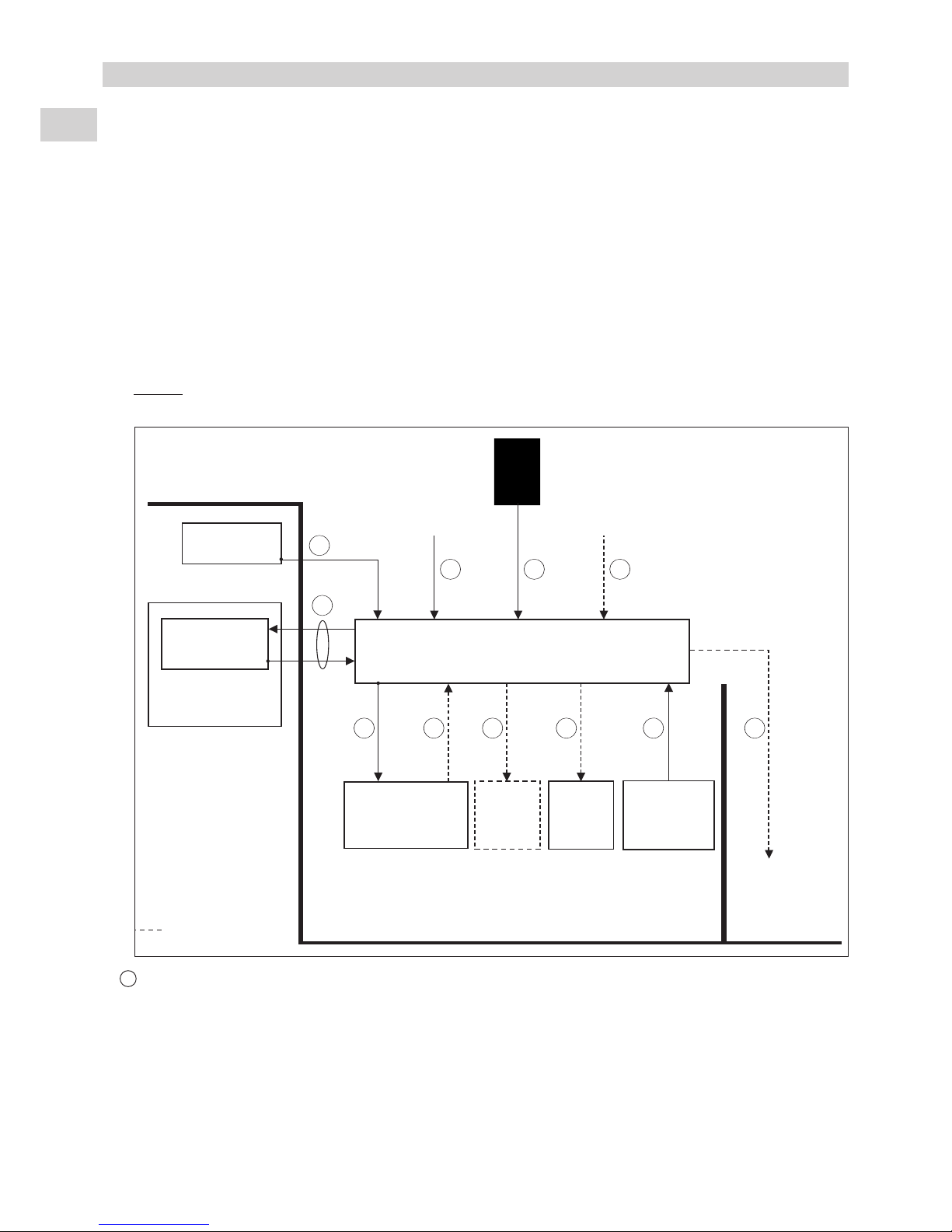
Technibel K 60 D 066 Z User manual

F
GB
I
E
D
KIT RÉGULATION POUR POMPE À CHALEUR EN RELÈVE DE CHAUDIÈRE
APPLICATION 1 ZONE RADIATEURS / ACTION “TOUT OU RIEN”
CONTROL KIT FOR HEAT PUMP IN CONJUNCTION WITH EXISTING BOILER
1 RADIATOR ZONE APPLICATION / “ON/OFF” ACTION
KIT REGOLAZIONE PER REFRIGERATORE IN POMPACALORE CON
CALDAIA DI INTEGRAZIONE
APPLICAZIONE 1 ZONA RADIATORI / AZIONE “TUTTO O NIENTE”
KIT DE REGULACIÓN PARA BOMBA DE CALOR CON CONEXIÓN DE CALDERA
APLICACIÓN UNA ZONA RADIADORES / ACCIÓN “TODO O NADA”
SET - STEUERMODUL UND SCHALTKASTEN FÜR WÄRMEPUMPE PLUS
BAUSEITIGE HEIZQUELLE
ANWENDUNGSFALL 1 ZONE HEIZKÖRPER / ZWEIPUNKTREGELUNG
Septembre 2008 10 11 484 - F.GB.I.E.D - 01
K 60 D 066 Z
NOTICE
D’INSTALLATION
INSTALLATION
INSTRUCTION
MANUALE
D’INSTALLAZIONE
MANUAL
DE INSTALACIÓN
AUFSTELLUNGS-
HANDBUCH
(Etiquette signalétique)

GB
2
CONTENTS
1 - Purpose - Use . . . . . . . . . . . . . . . . . . . . . . . . . . . . . . . . . . . . . . . . 2
2 - Precautions . . . . . . . . . . . . . . . . . . . . . . . . . . . . . . . . . . . . . . . . . . 2
3 - Composition . . . . . . . . . . . . . . . . . . . . . . . . . . . . . . . . . . . . . . . . . 2
4 - Operating principle . . . . . . . . . . . . . . . . . . . . . . . . . . . . . . . . . . . . 3
5 - Installation . . . . . . . . . . . . . . . . . . . . . . . . . . . . . . . . . . . . . . . . . . . 5
6 - Connections . . . . . . . . . . . . . . . . . . . . . . . . . . . . . . . . . . . . . . . . . 6
7 - Presentation of electronic control elements . . . . . . . . . . . . . . . . . 9
8- Operation . . . . . . . . . . . . . . . . . . . . . . . . . . . . . . . . . . . . . . . . . . 10
9 - Starting - Maintenance . . . . . . . . . . . . . . . . . . . . . . . . . . . . . . . . 17
10 - Electrical diagram . . . . . . . . . . . . . . . . . . . . . . . . . . . . . . . . . . . . 18
1 - PURPOSE - USE
• This control kit is designed to control radiator type central heating installations with a heat pump for relieving a boiler in
residential applications.
•Application: 1 zone with radiators - “On/Off” action on supplementary boiler application without domestic hot water (DHW).
MARKING
This product, marked with the symbol, complies with the essential requirements of the following Directives:
- Low voltage No. 2006/95/EC.
- Electromagnetic Compatibility No. 89/336 EEC, modified 92/31 and 93/68 EEC.
2 - PRECAUTIONS
Installation, commissioning and maintenance of this kit must be performed by qualified and authorised personnel, in
accordance with current standards and recognized trade practices.
Before doing any work on the installation, make sure it is switched off and all power supplies locked out.
IMPORTANT
• Consult the manuals of the system's various components:
- Generator.
- Boiler.
Before each start-up operation, make sure that the it is properly configured for the application.
See paragraph 8.7.
CAUTION
3 - COMPOSITION
• The kit includes:
- A control box to be installed in the comfort zone (see paragraph 5.1).
- An electrical control box is to be placed in the equipment room (see paragraph 5.4).
- An outside temperature sensor unit placed on the facade of the building (see paragraph 5.2).
-Awater temperature sensor, with its retaining clamp, is to be placed on the installation's return line (see paragraph 5.3).
•Control unit:
- Plastic wall-mounted control unit.
- Dimensions: height = 128 mm
width =86 mm
depth =34 mm
- Colour: White
- Class lll
-IP 30

GB
3
•Water temperature sensor:
- Metal cap:
length: 41 mm
max. diameter: 8 mm
- With 3.5 meters of cable and retaining
clamp.
•Outside temperature sensor:
- Installed in a box with cable gland.
Note:
This sensor must be installed in a location
that is sheltered from inclement weather.
See details in paragraph 5.2.
•Electrical control box:
- plastic box with transparent door + lock and wall mounting lugs + screws.
- grey colour, RAL 7035.
- IP 22, once installed.
- weight: 2.6 Kg.
-Equipment:
1-Heating control electronic board
2-Boiler authorisation relay
3-Control system circuit breaker
4-Terminal strip
5- Control board accessory location
“Bi-PAC” (see specific installation manual)
1
5
3
2
4
4 - OPERATING PRINCIPLE
• The kit is designed allow complete installation control from the parameterable control box.
•The orders given by the control box are transmitted (via a two-wire BUS) to installation elements through the control board which
drives the generator and authorises boiler operation.
• The generator and the boiler are controlled according to a setpoint resulting from the water temperature calculated according
to a water law (according to the outside temperature). Priority is given to thermodynamic heating.
• Water temperature control is managed in relation to the sensor to be placed on the installation's return line.

4
• Installation diagram:
Control box
with ambient
temperature
sensor
Direct action on the supplementary boiler
Decoupling bottle
Installation diagram for
indication - Not contractual.
Outside
sensor
230 VAC power supply
Control kit
K 60 D 066 Z
Heating
board
Boiler
without
DHW
Installation according to
current standards and
recognised trade
practices
Output control
valve
Generator connection
kit 70600112 or
70600122
Water
return
probe
Dirt separator
70600114
Generator
Note: install the strainer filter, supplied with the generator, on the water inlet
Radiators
Do not place the
thermostatic valve on
the radiator(s) located
in the room where the
control box is located
Control box with
ambient
temperature
sensor
Action on the supplementary circuit by On/Off
controlled valve
Decoupling bottle
Outside
sensor
230 VAC power supply
Installation according to
current standards and
recognised trade
practices
Dirt separator
70600114
Generator
Note: install the strainer filter, supplied with the generator, on the water inlet
Radiators
Do not place the
thermostatic valve on
the radiator(s) located
in the room where the
control box is located
(*) Installation circulator: if this circulator is built into the boiler, make sure that it functions permanently (as soon as power is
supplied to the installation), even when the boiler is off.
3-way valve
230 VAC -
70600116
"On/Off"
(*)
Generator connection
kit 70600112 or
70600122
Water
return
probe
Control kit K 60 D 066 Z
Heating
board
Boiler
without
DHW
Output control
valve
Mixing tank 70600118
(possibly required - provide if the
installation's water volume is insufficient)
Mixing tank 70600118
(possibly required - provide if the
installation's water volume is insufficient)
GB
Installation diagram for
indication - Not contractual.

GB
5
5.1 - CONTROL BOX INSTALLATION
• As the control unit is equipped with a temperature sensor, it must
be installed in a location that is representative of the temperature
of the comfort zone.
• Wall mounting: the unit must not be installed in corners, on
shelves or behind curtains, near sources or heat or directly
exposed to sunlight. The unit should be installed approximately
1.5 m above the floor.
• Open the box by removing the lower screw and secure the base
to the wall (mounting holes, item 1).
•Open the protective cover (screw 2) and connect the BUS link to
the control board (see chapter 6).
• Fit the control unit back on its base.
5.2 - INSTALLATION OF THE OUTSIDE TEMPERATURE SENSOR
• This sensor must be located outside in a location that is
representative of the temperature to be measured (on a wall
facing North/North-west) and located away from parasitic
heat sources (chimney, thermal bridge, etc..) and sheltered
from inclement weather (under a roof overhand, for
example).
• Connection as per paragraph 6.
5.3 - INSTALLATION OF THE WATER TEMPERATURE SENSOR
• To ensure proper operation:
-Ensure that the sensor is correctly secured to the piping. Use the metal retaining clamp supplied with this kit.
-Use thermoconductive paste to improve conductivity (not supplied).
- Insulate the assembly with insulating foam (not supplied).
5.4 - INSTALLATION OF THE ELECTRICAL CONTROL BOX
• To be installed in the equipment room (ambient temperature between 0 and 40°C). IP 22,
once installed.
• Plastic wall-mounted control box.
- Install the mounting lugs, supplied with the kit, on the box.
- Secure the box to the wall using the screws / anchors supplied with the kit.
• Electrical connections: see paragraph 6.
Note: The box must be supplied with 230 V / 1 / 50Hz.
1
2
Base
Rear view
5 - INSTALLATION
Mini 20 cm
1.50 m
Control unit
20 cm min.
244
244

GB
6
6.1 - GENERALITIES
• Electrical cabinet according EN 60 439-3.
• The electrical installation must comply with the standards and regulations applicable where the device is being installed (in
particular NF C 15-100 = IEC 364).
• Power supply for the cabinet: 230V/1/50Hz.
The acceptable voltage variation is +/- 10 % during operation.
•Class 1 device.
• Short circuit current: 4.5 kA (according EN 60 898).
• Device designed to be connected to a mains supply with a TT neutral point connection (Neutral connected to earth -
according NF C 15-100).
• The electrical connections must be fixed.
Use grommets for passing cables into the cabinet.
6.2 - PRINCIPLE
• See diagrams in paragraph 6.3. The connecting cables are not supplied.
Caution:
To avoid problems related to electromagnetic disturbances, do not route these cables near power cables.
AGenerator load shedding signal (if required)
- Two possibilities:
1) By a "remote info" signal coming from the electrical utility meter EDF (French electrical utility) (VLV "Very Low
Voltage" signal): 1 twisted pair (6/10) cable with shielding (screen grounded box side).
2) By a good quality, potential-free external contact.
- Contact closed = heat pump load shedding.
- 2-conductor cable, min. size 0.5mm2.
- Maximum length 25 meters.
- To be connected to the heating board A1.
6 - CONNECTIONS
D
E
BC
GF LH J X
A
Control unit
With built-in ambient temperature sensor.
To be installed in zone 1.
Outside air
temperature
On/Off
ALARM
GENERATOR
Installation
return water
temperature
On/Off
supplement
ary valve
(230 V)
Authorisation
Supplementary
heating
Power supply
230 V / 1 / 50Hz
(if required)
Heat pump load
shedding
Control box
Alarm Circulating
pump
(230 V)
Pilot wire
(230 V)
ZONE 1
Radiators
ZONE 2, as
required
Electric
convector
: Possible link

GB
7
B BUS
-2-conductor cable, min. size 1 mm2.
-Total length of the BUS connection: 40 meters (heating board A1 / control box connection).
-To be connected to the heating board A1.
CControl box power supply
- 230 V, single-phase, 50 Hz + ground (Class I).
-It must be supplied from a protection and disconnect device in compliance with current regulations.
- Cable 3G 1.5 mm2.
- To be connected directly on circuit breaker Q1 of the box (Terminals Uand N).
Note: The control box is supplied by the BUS.
D Outside temperature sensor
-2-conductor cable, min. size 0.5 mm2.
- Maximum length 25 meters.
- To be connected to the heating board A1.
E Generator control
- Shielded cable with 2 twisted pairs (shielding on generator side).
• 1 pair for generator on.
• 1 pair for the generator alarm signal.
- Min. cable size: 0.5 mm2.
- Maximum length 25 meters.
- To be connected to the heating board A1.
F Supplementary boiler authorisation
- Potential-free changeover contact, available on the box's terminal strip (terminals A, B, C).
- 2 A resitive at 230 Vac maximum.
- Actuated contact = boiler authorised.
- This signal is not mandatory if the supplementary valve is connected.
G Boiler alarm unavailable (as required)
- A contact from the boiler can possibly be connected on the heating board A1 for signalling on the control box and closure
of the supplementary valve.
-This contact must be potential-free and of good quality.
-Contact open = alarm.
- A maximum connection length of 25 meters and size 0.5 mm2.
H Boiler supplementary valve control (if any)
- "On/Off" control signal, 230 V / 50 Hz (30 VA maximum) available on the box's terminal strip:
-terminal 2 = common (connected to the Neutral)
-terminal 1 = valve opening control
- terminal 3 = valve closing control
-It is possible to connect either a 3-point valve (3 wires) (available as an accessory), or a spring type return valve (2
wires).
-Minimum cable size 0.75 mm2.
JCirculator (if any)
-It is possible to supply a circulator with 230 V / 1 / 50 Hz directly via the box's terminal strip (Terminals 4 - Neutral / 5 -
Phase / Ground).
-Maximum current 1.6 A(for a superior current strength, the signal must be relayed).
-Cable 3G 1.5 mm2.
- The circulator must have its own thermal protection (not supplied).
L Water temperature sensor (installation return)
- Sensor delivered with a cable measuring 3.5m long.
- This connection may be extended with a 2-conductor cable (minimum 0.5 mm2cross-section) and with a maximum
length of 25 meters.
- To be connected to the heating board A1.
X Pilot wire for electric convectors (if any)
-To send shut-down, "Anti-freeze" (prolonged absence) or "Eco" orders to electric convectors in zone 2. Convector
control (not supplied) must be adapted to receive this type of signal (standard GIFAM 4). Consult the manual of the
electric convectors.
-230 VAC signal from the heating board A1.
- 1.5 mm2single-pole cable adapted for the operating voltage.
-Max. number of convectors controlled by the pilot wire: 20.
-Note: The electrical power supplied to the convectors must be the same as that of the control.
Note: ensure that the ground connections of the various system components are interconnected.

GB
8
6.3 - BOX CONNECTING DETAILS
1 2
CN1
230V
CN3CN2 CN4
BUS
CN8
KA1
CN7 CN6 CN5
3
5 4 3 2 1 4 3 2 1 45 3 2 1 3 2 1
N U FP R1 R2 R3 C E1 E2 T+
H1
A1 C A2 C4
4 3 2 1 5
ALM/ACn/fr
6
3 2 1S1 C S2 C S3 A3 H2 H3
T- D1 D2 + -
1 2 3 4 1 2 3 4 1 2 3 4
12345ABC
F
H
C
B
A
X
E
A1
G
DL
Q1
N U
Power supply
230 V / 1 / 50 Hz
Control unit
Not used
Water return temperature
sensor
Outside temperature
sensor
Printed Circuit Board
Boiler
authorisation
Boiler fault contact unavailable
(as required).
Remove the bridge between Cand A3.
Ph N
Terminal XC
Electrical
utility
meter
Generator load
shedding
(if used)
Or
Electric
convector
pilot wire
(if used)
Open
Valve
(if used)
Common
Close
6.4 - CABLE ROUTING
Box top view
Box 230 VAC power supply BUS
Control signals and sensors
230 VAC connections
Circulator
Generator

GB
9
7 - PRESENTATION OF ELECTRONIC CONTROL ELEMENTS
7.1 - CONTROL UNIT
Rotary function selection knob (9 positions, left to right):
-Cooling: INACTIVE
-Heating, anti-freeze:Anti-freeze mode operation
-Heating, ECO: Heating mode operation with ECO setting
-Heating, Auto:Heating mode operation with hourly programming
-Heating, Confort: Heating mode operation with Comfort setting
-Stop
-Time setting
-Prog. Z1: Zone 1 program control (hourly / weekly)
-Prog. Z2: Zone 2 program control (hourly / weekly)
if activated
Push-button
for setpoint and parameter modification
Push-button
for setpoint and parameter modification
"Z/OK" push-button
Display selection zone 1 / zone 2 / outside temperature and validation
Liquid crystal display (LCD)
Micro-switch to activate a 2nd heating zone using electric convectors (see paragraph 8.5.). This micro-switch is located on the
back of the unit's printed circuit board. Remove the base to gain access to this switch.
Ambient temperature sensor
1
2
3
4
5
6
7
2
3
4
1
7
6
5
Day of the week
or parameter level
Override in progress
Hourly programming
Zone 1 display
Zone 2 display (if activated)
Supplementary heating authorisation
Outside temperature display
Telephone override activated
Comfort / ECO / Anti-freeze indication
• When off, the display indicates "OFF".
• When in operation, the normal reference display indicates:
- the setpoint temperature of zone 1,
- the current setting with the hourly program bar graph:
= Comfort
= ECO
No indication = Anti-freeze (prolonged absence)
- current day.
Generator load shedding

10
•The operating modes are selected using the rotary knob on the front of the control unit (see chapter 6.1 and user's manual).
8.1 - HEATING MODE
8 - OPERATION
7.2 - HEATING BOARD A1
• Allows control of the generator and to authorise boiler heating.
• It is connected to the control unit by the communication BUS.
1 2
CN1
A
G
T
C
230V
CN3 CN4
CN8 CN7 CN6 CN5
3
5 4 3 2 1 4 3 2 1 45 3 2 1 3 2 1
N U FP R1 R2 R3 C E1 E2 T+
H1A1 C A2 C4 3 2 1S1 C S2 C S3 A3 H2 H3
T- D1 D2 + -
1 2 3 4 1 2 3 4 1 2 3 4
BUS
or
Circulator control
Valve closure control
Supplementary unit / valve
opening authorisation
230 VAC power supply
Not used
(**) Boiler alarm input
unavailable
Not used
(**)
Generator fault input
(*) Generator On / Off output
(*) Generator H / C output
(not used)
Outside temperature
Installation return water
temperature
(*) Potential-free, normally-open contact
(**) Alarm on contact opening
A= Boiler control LED
G= Generator control LED
C= Communication BUS LED
T=Elec. utility load shedding Téléinfo LED (flashes if not connected)
7.3 - TEMPERATURE SENSORS
• Type CTN 10 KΩat 25 °C.
Temperature (°C) Temperature (°C)
-20 97 120 30 8 058
-15 72 980 35 6 532
-10 55 340 40 5 326
-5 42 340 45 4 368
032 660 50 3 502
525 400 55 2 936
10 19 900 60 2 488
15 15 710 65 2 082
20 12 490 70 1 751
25 10 000
Ohmic value (Ohm)
Ohmic value (Ohm)
Not used
Generator load
shedding
EDF
Not used
Pilot wire for electric convectors
GB
EDF = (Electricité de France) - electrical utility

GB
11
X
2K2K2K
Y
An outside temperature X
determines a resulting water
temperature setpoint Y.
The parameters determining
this water rule can be set by the
installer (see the table in
paragraph 8.7).
The resulting setpoint is
displayed at parameter 04.
If required, it can be corrected
depending on the ambient
temperature of the zone and the
automatic slope correction (see
paragraph 8.1.5.).
Water temperature setpoint
Outside temperature
Water temperature resulting
setpoint curve
Max. water temperature
(parameter 30)
Min. water temperature
(parameter 32)
Generator shutdown
threshold
(parameter 20)
Regional min. temperature
(parameter 21)
Supplementary boiler
authorization threshold
(parameter 22)
No heating
setpoint
(parameter 23)
Generator authorization
Supplementary boiler
authorisation
If generator alarm or if generator prohibited due
to excessively cold water or load shedding
8.1.2 - "COMFORT" HEATING MODE
•Temperature setpoint
- The heating can operate only if the outside temperature is less than the non-heating temperature.
- The generator is controlled via the heating board according to a resulting setpoint of the water temperature
installation return calculated according to an adjustable water rule determined by:
- the non-heating temperature (parameter 23),
-the regional minimum temperature (parameter 21),
-the minimum temperature of the water circuit (parameter 32),
- the maximum temperature of the water circuit (parameter 30).
The resulting setpoint calculated in this manner can be corrected by the temperature of the zone.
Adifference of +/- 1 degree of ambient temperature in relation to the heating setpoint temperature of the zone
(adjustable from 15 to 25 °C) causes the resulting setpoint (water temperature) to decrease or increase of 2 degrees,
respectively. However, this variation cannot exceed +/- 4 degrees.
In addition, a self-adapting system (if activated by the parameter P74) automatically adjusts the heating slope
according to the difference between the set point (ambiance) and ambient temperature. See details in paragraph
8.1.5.
•If the installation's water temperature exceeds the generator setpoint value, it shuts down and heating is
provided by the boiler only.
Caution: Make sure that the boiler setpoint allows the water temperature of the resulting setpoint to be obtained.
•Supplementary boiler authorisation (and valve actuation, as
the case may be)
-The supplementary heating via the boiler is activated if the
generator is not able to maintain the installation's water return
temperature at the calculated value (resulting set point).
-Caution:
During normal operation, supplementary heating is authorised
only if the outside temperature drops below the authorisation
threshold (parameter 22). However, it may be authorised for
higher temperatures if the generator is unavailable (due to an
alarm, safety cut-out or load shedding).
In case of an alarm on the boiler, this is not authorised.
Alternative generator / boiler operation:
If this type of operation is selected (parameter 72 = 0),
simultaneous operation of the generator and supplementary
heating is prohibited: if the outside temperature is below the
authorisation threshold (parameter 22), the generator shuts
down and heating is ensured only by the boiler.
Water
temperature
Generator
command
Supplementary boiler
authorisation
Resulting setpoint
Supplementary
heating control shift
(parameter P40)
8.1.1 - HEATING OPERATING DIAGRAM
Circulation pump activation

GB
12
•Generator operating safety features in heating mode
-A safety device on the water temperature (installation return) prohibits generator operation if this temperature is
below the thermodynamic heating authorization threshold (parameter 36). In this case, only the boiler is authorised
to raise the water temperature and allow the generator to function, regardless of the outside temperature. The
activation of this safety feature is indicated by the flashing of the display.
- Generator operation is prohibited if the outside temperature is below the generator's shut-off threshold (parameter
20). Only the boiler is authorised.
8.1.3 - "ECONOMY" HEATING MODE
• The switch to "ECO" mode lowers the ambient temperature setpoint by a value than can be adjusted from 1 to 6 °K
(parameter 24).
• Switching from "Comfort" to "ECO" is accomplished either by hourly programming, weekly programming by zone or by
actuating the rotary knob for the entire installation.
• In the case of hourly programming, the user can activate a temporary override (1 hour + periods of 1 hour during the
current day) per zone.
8.1.4 - "ANTI-FREEZE" HEATING MODE (prolonged absence)
• Selection is made using the rotary knob on the control
unit for the entire installation.
• The resulting water temperature setpoint shifts to an
adjustable value via parameter 29. The heating
(generator + boiler if required) is actuated according
to the ambient temperature setpoint, which can be
adjusted by parameter 25.
8.1.5 - SELF-ADAPTING HEATING SLOPE
•System activated by parameter 74 = 1.
• Principle: the theoretical slope calculated according to the parameters of the control equipment is automatically
corrected by the system by adding (or subtracting) a correcting coefficient (the value of which is displayed in parameter
90). This coefficient is determined by analysing, in terms of a 24-hour continuous operating period in "Comfort"
heating mode, the behaviour of the ambient temperature in relation to the setpoint temperature (in "Comfort" mode).
This analysis is also weighted by the difference between the setpoint and the outdoor temperature.
• Example:
(P) = Theoretical slope
(P + K) = Slope increased with ambient temperature
below the setpoint
(P - K) = Slope decreased with ambient
temperature above the setpoint
Note:
Regardless of the slope, the resulting setpoint cannot
exceed the maximum temperature value of the water
(parameter 30) (possibly corrected according to the
ambient temperature).
Example:
To adjust the following parameters:
.Parameter 21 = 0°C
. Parameter 23 = 20°C
. Parameter 30 = 60°C
. Parameter 32 = 30°C
Theoretic slope value P= = 1.50.
If the value of the coefficient Kread on parameter 90 is “10” (hundredths), the actual slope becomes:
P+ K= 1.50 + 0.10 = 1.60.
The value of this coefficient is reset in the event of:
- deactivation of the system by parameter 74,
- re-initialisation of the parameters by parameter 60,
-an application change by parameter 70.
8.2 - COOLING MODE
Inactive
Note: The selection of this mode, using the rotary knob, causes the system to shut down (“OFF”).
60 - 30
20 - 0
Ambient temperature
Heating command
Anti-freeze mode ambient temperature setpoint
(P+K)
(P-K)
(P)
Water temperature
Peak limiting
Max. water
temperature
(parameter 30)
Min. water
temperature
(parameter 32)
Regional min.
temperature
(parameter 21)
Heating authorisation
threshold
(parameter 23)
Outside
temperature

GB
13
8.3 - FORCING OF CONTROL OUTPUTS
• Forcing: for maintenance operations only, when the system is "OFF", it is possible to force the control of the following outputs
by setting to parameter to "1":
-Parameter 64: circulating pump
- Parameter 67: generator
-Parameter 69: supplementary boiler
Caution:
At the end of the operation, forcing must be deactivated (by returning the parameters "0") before
restarting the installation.
8.4 - GENERATOR LOAD SHEDDING
•This can be done:
- either by a potential-free contact,
-or from a "“Tele-Info” signal sent by the electrical utility meter (per specification EDF HN 44-S-81).
• Prohibits operation of the generator and the 2nd electric convector zone, if any.
• Signalled by icon on the display unit.
8.5 - 2nd ZONE - ELECTRIC CONVECTORS
•A2
nd zone equipped with electric convectors can also be managed (Max. number = 20). These appliances must be equipped
with an electronic thermostat (not included) able to receive signals via a 230 VAC pilot wire (standard GIFAM 4).
• The 2nd zone is activated by setting the microswitch in the back of the control unit to the "ON" position.
- In "Comfort", "ECO" or "Anti-freeze" heating modes, the corresponding signals are transmitted to the 2nd zone.
- In Off position, the signal is transmitted to the 2nd zone.
- In heating mode with hourly programming, the "Comfort" or "ECO" signals are transmitted to the 2nd zone according
to the corresponding hourly programming.
Note:
In case of load shedding, a shut-down signal is transmitted to the 2nd zone.
- In heating mode, the display unit indicates for the zone 2 "HEAT.
8.6 - CIRCULATOR CONTROL
• In heating mode (Comfort / ECO / Anti-freeze), the installation's circulating pump is actuated if the outside temperature is
below the non-heating threshold.
•Circulating pump shutdown is delayed 1 minute.
• A degripping device allows the circulating pump to start automatically, for 3 seconds every 24 hours, if it is off.
• The circulator must have its own thermal protection (not supplied).
•Note:
The circulating pump built into the generator is factory-set to operate constantly as soon as generator power is on.
It is possible to operate this circulating pump only when the generator is controlled by this system.
To do this, on the generator's ECH regulator, change parameter H20 to “4” (see generator manual).
8.7 - PARAMETERS
•Access:
- 2 access levels:
-Level 1, read only, with direct access for parameters 1 to 19,
- Level 2, ("technical level") accessible by password ("see last page").
This level is entered via parameter 20, although all parameters are accessible.
Procedure:
1°) Simultaneously press and hold the buttons and for 5 seconds, until
the screen displays PArA.
2°) Select the
User menu = Level 1 or Installer = Level 2 using the and
buttons.
1: User
2: Installer

3°)* To access level 1, press “Z/OK.
The display indicates the first
parameter “P01”.
Press the or keys to shift from
one parameter to another.
To know the value of the parameter,
press “Z/OK”.
To redisplay the value of the
parameter, press “Z/OK” again.
3Bis°)* To access level 2, press “Z/OK”.
The display shows “ ”.
Enter the password digit by digit, by selecting the desired digit using the or buttons and by confirming with
“Z/OK”. Once the password is entered, the display then indicates “P20” which is the first parameter of this level.
To display the value of a parameter, select it using the or keys and press “Z/OK”.
To modify this parameter, if needed, press keys or .
To redisplay the value of the parameter, press “Z/OK” again.
4°) To exit the parameterisation procedure, press and hold “Z/OK”.
In all cases, the display returns to normal automatically after a few minutes of inactivity.
The parameters can be accessed and modified both in operation and when shut down, except for those for
installation configuration and default parameterisation which can only be accessed and modified when the
installation is shut down.
Note:
The flashing parameter values are those that can be modified. Otherwise, the display remains steady.
•Configuration of installation type
IMPORTANT: THE FOLLOWING ELEMENTS MUST BE CARRIED OUT EACH TIME THE INSTALLATION IS
PLACED INTO SERVICE
-For the application, parameter 70 must be set to 1.
-Procedure:
1) Set the rotary knob on the control unit to the "Stop" position.
2) Go to parameter 70. Press the "Z/OK" button; the value of the parameter is displayed. This value may be read or
modified using the and buttons if the system is in the "Stop" position. If parameters are modified, an
initialisation process is launched automatically (the "init" message is displayed). When initialisation is completed, the
display returns to parameter 70.
Note: If this parameter is set in other than the "Stop" position, the "STOP" message flashes and the parameter
cannot be modified.
3) Check and adjust the other configuration parameters, as required:
• Parameter 72 = Simultaneous generator and supplementary heating operation.
• Parameter 74 = Heating slope self-adaptation activation.
4) Once the configuration parameters have been verified, disconnect and re-establish the system's power supply to
reset the control system.
•Default configuration
-This enables the default values (see list) of all parameters to be reset according to the type of installation.
- Procedure:
- Set the rotary knob on the control unit to the "Stop" position.
- Go to parameter 60. Press the "Z/OK" button; the "init" message is displayed.
Note:
If this parameter is set in other than the "Stop" position, the word "STOP" flashes and the configuration cannot be
launched.
- Press and hold the "Z/OK" button for 5 seconds to launch the default configuration. The "init" message flashes.
When initialisation is completed, the display returns to parameter 60.
•Calibration of temperature sensors ("Offset")
- The value displayed by certain sensors may be adjusted. To do this, move to the corresponding parameter and enter
the desired value (+/- 3 degrees maximum).
GB
14
Access to the 1st parameter (P01) Display of the parameter value

GB
15
1 Radiators zone
No. Designation Access Range Value / Default
Status:
01 Outside temperature D-40 / +90°C
Read only
02 Installation return water temperature D-40 / +90°C
03 (not used)
04 Water temperature resulting setpoint (installation return) D15 / 75°C
05 (not used)
06 (not used)
07 (not used)
08 Temperature ambiante zone 1 D-40 / +90°C
09 (not used)
10 Generator control output status D0/1
11 (not used)
12 Boiler control output status (or ON/OFF valve opening) D0/1
13 On/Off valve closure control status D 0/1
14 Circulating pump control output status D0/1
Air temperature settings:
20 Generator shut-down threshold (outside temperature) T-15/ +5°C -5°C
21 Regional min. temperature (outside temperature) T-20 / +5°C -7°C
22 Supplementary authorization threshold (outside temperature) T-5 / +20°C 5°C
23 No heating threshold (outside temperature) T10 / 25°C 17°C
24 Lowering of ECO temperature (ambiente) T1 / 6K 3K
25 Anti-freeze ambiance setpoint T8 / 18°C 12°C
Water temperature settings:
29 Water temperature setpoint in "anti-freeze" mode (return) T 20 / 40°C 30°C
30 Heating water max. temperature (return) T25 / 60°C 50°C
31 (not used)
32 Heating water min. temperature (return) T17 / 40°C 20°C
33 (not used)
34 (not used)
35 (not used)
36 Thermodynamic heating authorization threshold (return) T10 / 20°C 15°C
37 (not used)
38 (not used)
39 (not used)
40 Supplementary triggering shift T1 / 10K 3K
Sensor:
50 Outside sensor T+ or -3K 0
51 Zone 1 ambient temperature sensor T+ or -3K 0
52 (not used)
53 Installation return water temperature sensor T+ or -3K 0
54 (not used)
55 (not used)
56 (not used)
57 (not used)
Miscellaneous and maintenance:
60 Default configuration TInit
61 TYPHONE language selection (1 = F ; 2 = GB) T1 / 2 1
62 TYPHONE access code T0 / 9999 1234
63 (not used)
64 Circulator control forcing T0 / 1 0
65 (not used)
66 (not used)
67 Generator control forcing T0 / 1 0
68 (not used)
69 Boiler control forcing T0 / 1 0

GB
16
1 Radiators zone
No. Designation Access Range Value / Default
Configuration: to regulate with
70 Installation type T1 / 5
1 = 1 radiator zone ------------------------------------------------------- ------------ -------------------- ------------- > 1
2 = 1 radiator zone with proportional control valve
3 = 1 floor zone with proportional control valve
4 = 2 mixed zones (floor + radiators)
5 = 2 floor zones
71 (not used)
72 Simultaneous generator + supplementary operation (1 = simultaneous) T0 / 1 1
73 (not used)
74 Slope self-adaptation activation / deactivation (1 = Activated) T 0/1 1
Software versions: Read only
80 Control unit T
81 Heating board T
82 (not used)
83 (not used)
Correction coefficients:
90 Zone 1 self-adaptation correction coefficient (**) T Read only
91 (not used)
Ambience setpoints:
Heating setpoint zone 1
D
Direct
keyboard
access
15 / 25°C 20°C
(**) Does not appear if “P74” = 1
“D” = access without password
“T” = access with password
8.8 - ALARMS
• The alarms are indicated by a message flashing alternately on the display.
•Automatic reset: the alarm disappears when the source of the fault is corrected.
•Note:
The alarms are displayed even if the system is shutdown.
If several alarms occur simultaneously, the various codes are displayed alternately.
(*) See the type of fault on the generator.
8.9 - TELEPHONE CONTROL
•ADELTA-DORE TYPHONE 500 type telephone control box can be connected to the communication bus (available from
DELTA-DORE distributors).
Caution:
Its date-code number must be greater than 05-24.
Consult the manual supplied with the telephone control.
ALARM CODE ACTION
RESET
Gr (*)
Boiler unavailable HE
Prohibits operation of the supplementary boiler + On/Off valve
closure
Auto
Installation return
water sensor fault
Auto
Auto
Auto
System shut-down
System shut-down
Communication or
system fault
Cn
System shut-down
Outside air sensor
fault
SAE
Operation in Anti-freeze mode (but with no condition on the outside
temperature)
Ambience sensor fault
zone 1
SEIn
SA1
Generator fault
Suppression of the heating authorization threshold according to the
outside temperature
Auto
Auto

GB
17
• By calling the telephone line on which the TYPHONE is recorded, the user can:
-know the ambient temperature of zone 1,
- know the setpoint temperature of the current mode of zone 1,
-send an override setpoint.
In case of setpoint modification, zone 1 and possible zone 2 operates in “COMFORT” mode.
This override is indicated by an index on the LCD.
Any action on the rotary knob deactivates the override and extinguishes the indicator.
•Parameters possibilities:
- access code change (parameter 62),
-interface language change - French / English (parameter 61).
8.10 - POWER FAILURE
• In case of power failure, the parameters and settings are maintained. If the power outage exceeds 6 hours, the time setting
will have to be corrected.
8.11 - MISCELLANEOUS
•Mode changes using the rotary knob (Heating / Cooling
(not used) /
Anti-freeze / Stop) are delayed 10 seconds in order to
filter inappropriate actions. However, the "Time Setting" and "Hourly Programming" positions do not have the time delay
feature.
• The authorization thresholds on the water temperature are cut-off values with a differential of 1K for the reset.
9.1 - STARTING
9.1.1 - PRELIMINARY CHECKS
Check:
• Ensure that the hydraulic connections are properly tight and that the hydraulic system operates correctly:
-purge of circuits, valve position, hydraulic pressure (1.5 to 3 bar).
• For leaks.
• Electrical cables and wires are well secured to their connection terminals. Loose terminals can cause heat build-up on
the terminal board and malfunctions.
•Ensure that the electric cables are properly protected from all sheet metal edges or metal parts that could damage them.
• Ensure that control cables and power cables are properly separated.
•Check that the unit is properly grounded.
•For tools or foreign objects in the units and control box.
• The correct installation of the heat pump and boiler. These elements must be ready to operate. Refer to the
corresponding manuals.
9.1.2 - CONTROL PARAMETERISATION
• Parameterisation is performed on the control box.
• Set the button on the installation's control box to “OFF”.
• Check the parameterisation and, if required, adapt it to the type of application and according to the installation conditions
(see paragraph 8.7).
9.1.3 - ADDITIONAL CHECKS
•With the control box button on “OFF”, turn installation power on.
• Force operation of the installation's circulating pump.
• Make sure that the generator's circulator is operating and adjust the water output as required (with the control valve).
•Check that water is properly circulating in the installation (valve position).
•Make sure to purge the circuits and check the hydraulic pressure.
• Make sure that the generator has started in the desired mode.
• Make sure that the supplementary valve is operating, possibly by forcing the opening.
•Check the generator and boiler setpoints.
•Check the indications of the temperature sensors; perform an “Offset” calibration of these sensors if required.
.
9 - STARTING - MAINTENANCE
Before doing any work on the installation, make sure it is switched off and all power supplies locked out.
Any work must be carried out by personnel qualified and authorised to work on this type of machine.
IMPORTANT NOTE

9.1.4 - START-UP
• Position the control box button on the desired operating mode.
•Check general installation operation (temperatures, outputs,...).
.
CAUTION:In order for the automatic heating slope correction system operate at an optimum level, we recommend
that, when starting the installation, the system be operated in Comfort heating mode for 2 to 3 days without modifying
the ambient setpoint.
Proceed in the same manner if the correction coefficient was reset. See paragraph 8.1.5.
9.2 - MAINTENANCE
•Perform the following operations at least once per year (the frequency of operations depends on the installation and
operating conditions):
- Check the composition and condition of the coolant.
- Check operating points and setpoints.
- Check the safety devices.
- Dust the electrical box.
- Ensure that all electrical connections are properly tight.
- Check the ground connections.
- Verification of the hydraulic circuit (cleaning of the strainer filter and drip pan, water quality, purge, pressure, etc.).
- Verification of the supplementary valve.
• For the generator and the boiler, refer to the instructions specific to these devices.
18
GB
10 - ELECTRICAL DIAGRAM
A1 Heating control board
KA1 Supplementary heating authorisation auxiliary relay
Q1 Control circuit breaker 230 VAC
Component symbols
10 05 826 - 01
A1
4
3
12
L1
3
54
2
1
31 2
O2
O1
O3
CA B
Q1
6A
PE
KA1
KA1
230V
T-T+E2E1
H3H2H1A3
-D2D1 +CR3R2R1FP
A2CCA11342S3S2CCS1
431 243214321321
1235 4321231412345
CN4CN3CN2CN1
CN5CN6CN7CN8
C
UN
U
N
230 V power supply
Boiler
alarm
HP
(Heat pump)
On / Off
Default
Boiler Circulating pump
Supplementary valve
Pilot wire
Supplementary
heating
Inlet
(Teleinfo) Remote info
Inlet
Load shedding
BUS
BUS
Outdoor sensor
Water return probe

GB
19

F
GB
D
I
E
Table of contents
Other Technibel Control Unit manuals
Popular Control Unit manuals by other brands

Kitz
Kitz F14A Operation, maintenance, and installation instructions

Mitsubishi Electric
Mitsubishi Electric AJ65FBTA42-16DT user manual

Sungrow
Sungrow EyeW485-H Quick use manual

Anybus
Anybus CompactCom 40 Modbus-TCP Network guide

Pneucon
Pneucon Globe Installation, maintenance and operation manual

Gascat
Gascat JR Series Installation, maintenance and operation manual