ABOUT
THE
PEAK.SIGNAL.CHECK
SWITCH
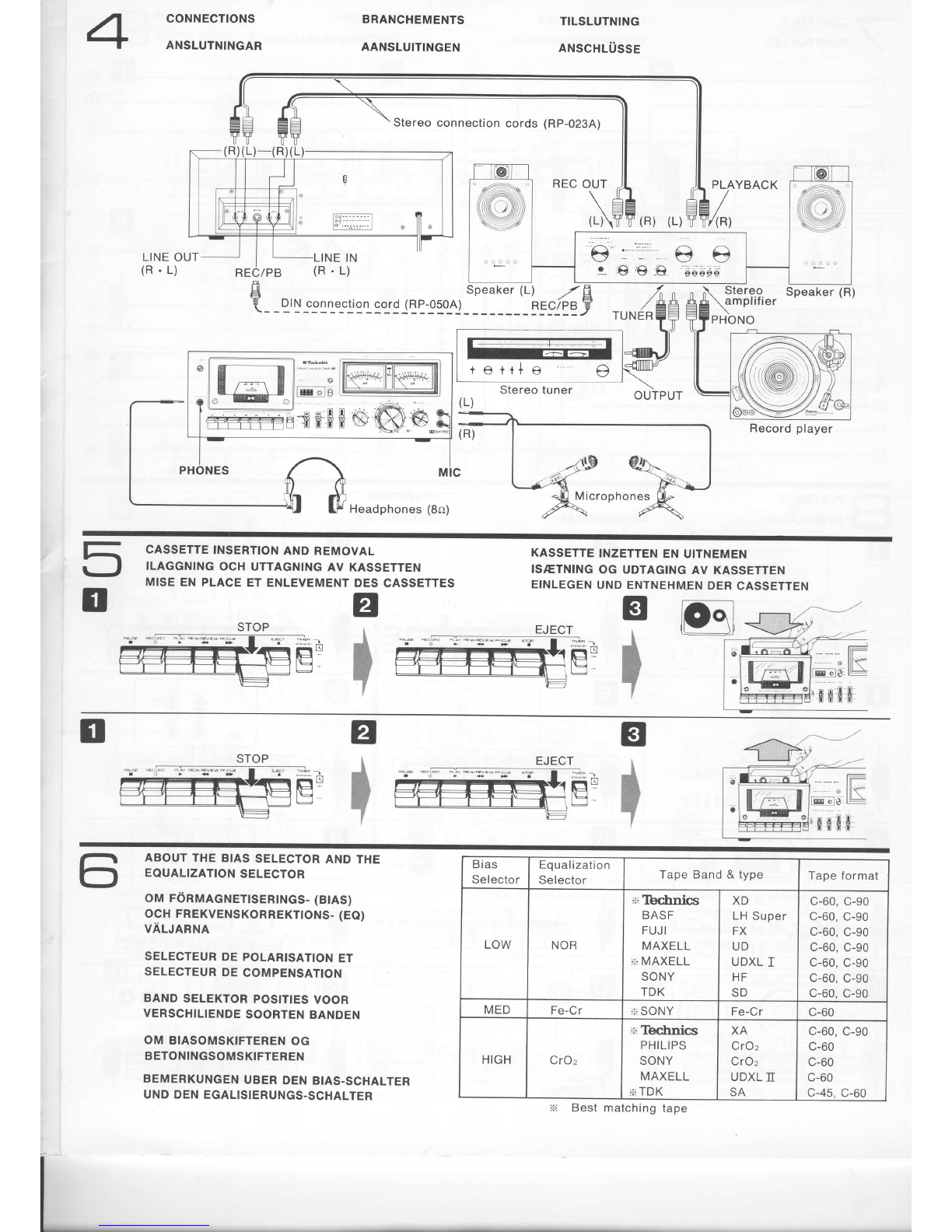
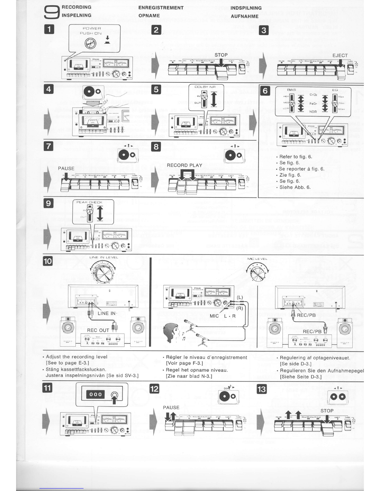
Adjustment
ofthe recording
level
(Refer
tolig.
9.)
Although
the recording
level is usually
adjusted
simply
sothat
the indication
needles
ofthe peaklevel/VU
meters
do notexceed
the "0 dB" indication
at maximum
deflec-
tion,
this unithas
a Peak-signal-check
switch
which
makes
it possible
to make
even more precise
ad.justment,
as de-
scribed
below.
1. Level adiustment
by using the peak-signal-check
switch
Meterfluctuations
for
are as shown
below. momentary
and continuous
sounds
=osr1t;Iiiilr,&it',
,=
_-111';
' "'[i" i;'>-+
. Set the Peak-signal-check
switch
tothe
"OUT"
position,
and adjust the recording
level, using the Line input
level controls, so that the
indication needles do not
exceed the "0 dB" mark.
. Then set the Peak-signal-
check switch to the "lN"
position. lf, at the peak of
pulse-like
sounds,
the indi-
cation needles exceed the
"+6 dB" mark
onthe rower
scale of the meters,reduce
the setting
of the Line input
level controls so that the
needles don't exceed the
"*6 dB" mark.
. Occasionally set the Peak-
signal-check switch to the
"OUT" position to confirm
that the indication
is less
than
"0 dB."
OUT
1
\dE}
2. Difference
between
dellection
of indication
needlesat
"OUT" positions
Because
the response
of indication
needles is slow for
ordinary
Ievel
meters,
the level
of instantaneous
sounds
is
notcorrectly
indicated,
which means that large instanta_
neous
sounds
may become
distorted
when recoroeo.
This
unitincludes
a Peak-signal-check
switchwhich,
when
set to the "lN" position,
precisely
indicates
the level
of
suchinstantaneous
sounds.
The Peak level/VUmeters of this unit have two scales
which
show
theoutputlevet.
When
the Peak-signal-check
switch
is setto the "lN" oosi-
tion,
the lower
scale
can be usedfor readout
up
to +6 dB.
Whenthe Peak-signal-check
switch is set to the ,,OUT,'
position,
the upper scale can be used for readout
uo to
+3 dB.
-+-- "lt/UW,'\"
Momentarysound Continuous
sound
=o
_=a'ir\'"="J5=+
Peak-signal-check
switch
I
IN
*t?,,,l]rrl}i5i
W=,,=
vi.ti;) +
ii:.::l:]i,,
,"'.
?.1ii?,:r =
]-ga'" solars"JS--*
48l
Dolby Recording
This
unitincludes
theDolby
noise-reduction
system,
which
reduces
tapenoise
to a remarkable
degree.
Briefly,
the systemworks as follows:
At low sound
levels
(where
tape noise
is most
noticeable),
the high-frequency
portion
of the sound is recorded
at a higher level.
Tape
noise
is not
amolified.
During
playback,
the level
of
onlythat
portion
ofthe signal
which
was
increased
atthetime
of
the
recording,
aswell
as
tape noise,
is reduced
by a like amount.This causes
the
signal
to
beheard
ata normal
level,
and
thetape
noise
to
be
reduced
si
gnif
icantly.
Monitoring
To
listen
tothe
recording
asitis
beingmade,
simply
plug
a
set of stereoheadphones(8o)
intothe Headphones
jack,
Youmay alsolisten
tothe program
as it is being
recorded
if
your
receiver
or amplifieris
equippedwith
a Tape-moni-
tor switch.
Note:
In
the
sameway asfor playback,
an arnplilier
can
also
be used
lor monitoring.
Note,however,ifthe recording
is beingmad€
via a connectionmade to the Record/
Playback
connection
socket,that monitoring
can be
done
onlywith headphones.
Mix Recording (Reler to fig. 15.)
This
unit
canbe usedfor makingmixed
recordings
ofthe
mlcrophone
input
andthe line
input.
. Mixed
recordings
can be made by simply
making
the
microphone
andline
input
connections.
. For
balanced
mix
recording,
adjust
thelevels
while
moni-
toring
through
headphones.
. When
not making
a mix recording,
setthe Input
Level
Controls
not
being
used
(Microphone
or
Lineinput)
tothe
minimum
"0' position.