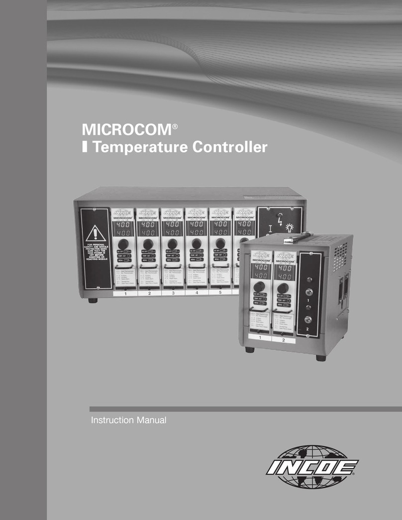
Technologies Paving Innovation TC101 User manual

TC101 TEMPERATURE
CONTROLLER
User Manual

Kratbjerg 214 - DK 3480 Fredensborg - Denmark - Phone: +45 48 48 26 33 - Email: sales@tf-technologies.com
www.tf-technologies.com

3
User Manual
TC101 TEMPERAURE
CONTROLLER
www.tf-technologies.com

4
Content and structure
This User Manual for TC101 Temper-
ature Controller covers specic part
numbers
S-50153
and
S-50168
has
been developed to the operator to pro-
vide necessary information to operate
the TC101 Temperature Controller.
The User Manual is a practical guide for
the operation of TC101 Temperature
Controller. This manual has been dived-
ed into colour-coded sections, enabling
the user easily look up the potential
subject of interest.
TC100 Temperature Controller
S-50153 & S-50168
About TC101 Temperature Controller User Manual
Copyright
All information, text and pictures are the
intellectual property of, and copyrighted
material of TF-Technologies A/S. All rights
are reserved. The User Manual may not
be copied, displayed, quoted, published,
sold, modied, or distributed without the
written consent of TF-Technologies A/S.
Disclaimer
TF-Technologies A/S and its distributors
may not be held liable for potential edi-
torial errors, omissions or failure eects.
Suggestions regarding updates or correc-
tion of potential errors are appreciated.
Contact information
TF-Technologies A/S
Kratbjerg 214
3480 Fredensborg
Denmark
T: +45 4848 2633
E: sales@tf-technologies.com
User manual information
Document name: TC101
Temperature
Controller
User Manual
Document number: G702303
Publication date: 29 January 2022
Check for User Manual updates:
www.tf-technologies.com/paving-academy
About this manual

5
TC101 Temperature Controller
The TC101 is a Temperature Controller,
which monitors and maintains a user de-
ned temperature of material contained
in hot-boxes and similar containers. This
feature prevents overheating of the ma-
terial and maintains the optimal tempera-
ture for the contained material.
These part numbers have a built-in ”Re-
start” feature, should the burner ame
be extinguished or not light on with the
initial system start up. Ignition will re-
start on a continuous 3 minute time cycle,
until the burner in question re-lights or
the ”OFF” button is operated.
These part numbers are former versions
of the TC101 Temperature Controller
and do not comply with the 2006/42/EC
Machinery Directive (MD). Please refer to
part numbers S-50121 and S-50122 with
additional safety features and without
automatic re-ignition for MD compliance.
Symbol overview
This user manual uses a range of symbols
and warning notications throughout the
manual to make the operator aware of im-
portant safety measures or information re-
garding operation. The following symbols
are used in this manual:
About this manual
1.
2.
3.
Step-by-step instructions
Indicates a step-by-step instruc-
tion, where a particular order
of actions is required or recom-
mended

6
Operation
Operation
• Burner LED
This LED indicates that the “BURNER”
output is driven to ground(/turned on)
• Power switch
The power switch has two positions.
In the middle position (OFF), power is
turned o, and no outputs are active.
In the lower position (ON), power is
on, and outputs are controlled by the
electronics
• TEMP. SET
This switch determines what information
is displayed. When held upwards (TEMP.
SET position), the selected temperature
is displayed and during this mode it is
also possible to select/reselect a material
temperature by turning the TEMP.ADJ.
turning knob
In the middle position, the current mate-
rial temperature is displayed
• Display
This is a 3 digit LED display, which
shows temperature and various error
codes
• Error chart
This is just a printed error chart,
which shows possible error-codes. All
error codes will ash in the display to
attract attention. (See troubleshoot-
ing section for full explanation)
• TEMP.ADJ.
This knob adjusts the selected tem-
perature within a range of either 20°
C - 90° C (S-50153) or 50° C - 175°
C (S-50168). As mentioned it is used
in conjunction with the TEMP. SET
switch (3)
Burner LED
Power Switch
TEMP. SET
Display
Error Chart
TEMP.ADJ

7
Operation
• Mounting screws
All mounting screws are 3 x 8 mm
• Connector
This is the Temperature Controller’s only
international connector. The pin assign-
ment is as follows:
0. Flame error input.
1. Sensor input.
2. Sensor input.
3. Burner output.
4. Not connected
5. + 12 Volts DC.
6. 0 Volts (Ground)
• Metal Shield
This reduces electrical interference.
Display
Error Chart
TEMP.ADJ
Mounting srew hole
Connector
Metal shield

8
1
2
3
1.
2.
3.
Description of operation
When powered up and the control switch
is in the “ON” position, the display will read
8.8.8. for approximately one second, then
1.01 followed by 0.02 (or similar digits).
The current screed temperature will then
be displayed.
The state of the burner output is indicated
by the burner LEDs (1) in the display. When
the preset temperature is reached, the
module (Micro Processor) will deactivate
burner output.
It is possible to view the preset
temperature setting, at any time by
switching the TEMP. SET switch (3)
Temperature adjustment
The system is designed for simple
operation, and only one adjustment is
required, the temperature setpoint setting.
Fig. 3 - TC101 Temperature Controller in a box
The temperature adjust-
ment range is from either
20° C - 90° C (S-50153) or
50° C - 175° C (S-50168).
To adjust the temperature,
ensure power supply is “on”
and operate module control
switch (2) to “ON” position
Hold the TEMP. SET switch
(3) upwards and turn
“TEMP.ADJ.” turning knob to
desired “Cut out” temper-
ature, then release TEMP.
SET switch.
The system will now operate
automatically and burners
will deactivate at the new
preset temperature. Burners
will reactivate when the
temperature has dropped 2°
C below the setpoint.r with
4mm or 5/32 inch screws
Step-by-step instruction for
Temperature preset
(cut out temperature)
Operation

9
Fails startup Damaged
Failes in operation Connection
Erratic display Sensor type
Unstable temperature Sensor connection
Display shows error-code “---“ Low voltage
Display shows error-code “OL“ Sensor
Display shows error-code “SE“ Sensor/cable
Display shows error-code “FE“ Ignition system
Display shows error-code “F99“ Overload
•
Check connector for sucient coltage at the con-
nector. If this is OK, then the module is probably
damaged.
•
Check system wiring and all connectors for correct
connections.
•
Incorrect sensor type used. Replace sensor with
proper PT-100 type.
•
If displayed temperature is higher than actual
temperature, some unwanted resistance is connected
in series with the sensor. This could be the use of
very thin cables or bad connections on the sensor
cable. Recommended cables should be no less than
0.75 mm2
•
Check sensor connectors, if all connections found OK,
replace sensor.
•
This indicates low supply voltage. Check the battery
voltage. This should be above 11 Volts.
•
Low voltage can also be caused by two loads sharing
the same small cable. (High resistance). Generally this
instrument should be directly connected to the battery
to avoid electrical interference and voltage drop.
•
This indicates that the actual temperature is higher
than the adjustment range. That might happen if the
sensor is defective
•
Sensor is defective, short-circuit
•
Sensor is defective, open
•
Sensor cable failure
•
This flame-error code indicates that the Temperature
Controller has received error-input on connector-pin 0.
(Probably because one of the connected ignition-box-
es cannot detect any flame).
•
Check the ignition system
•
This indicates overload of the Temperature Controller’s
burner output.
Trouble-Shooting
Symptom Probable Cause Appropriate Action
Appendix

10
Display is disutbed TC101
Instrument resest, shows “8.8.8“ Electrical interference
Shuts down after 7 sec. Condensation
•
This is probably because the TC101 and one or more
of the gas-valves that it controls share a common
power supply cable. As mentioned earlier the TC101
should have its own large cables directly connected
to the battery
•
This indicates some sort of electrical interference, or
incorrect wiring
•
This is the most common problem experienced with
the system, and in general is caused by condensation
built up on the ”HT” leads, after an overnight machine
shut down. The problem can be rectified by wiping
the ”HT” leads.
If the fault persists check the following:
•
One person needs to turn on the TC101 system, while
another person observes the yellow led indicators on
the FCB24/FCE24 (or similar TF-Technologies) ignition
boxes.
•
The indicators should be on and ”STEADY”, if one or
more of the yellow indicators are flickering it indicates
a possible problem in the area of that specific burner,
check the following:
1.Gas pressure (As per machine manufacturers specifi-
cations)
2. Spark plug gap (Approx. 3-4mm)
3. Spark plug electrode position (Earth electrode must
face flame direction
4. Air to gas ratio
NOTE: Ignition boxes (FCB24/FCE24 or similar) must
be fitted away from heat source.
Symptom Probable Cause Appropriate Action
Appendix

11
Fig. 2 - Overview of MatManagerTM paving quality system mounted on asphalt paver
Appendix
Technical Specication (data sheets)

12
Appendix

13
Table of contents


