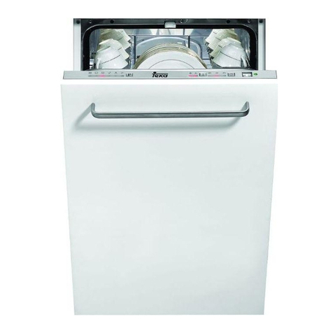
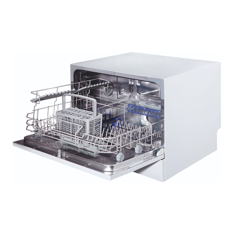
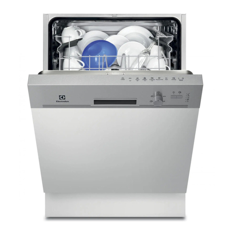
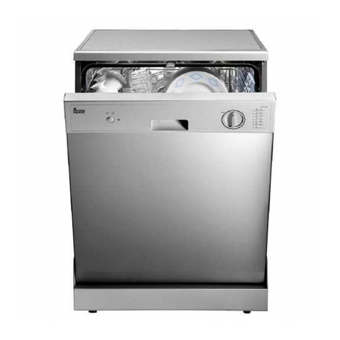
Teka LP2 140 User manual

Service Manual
MSDW16012
(updated 28/04/2020)
Models:
LP2 140
LP8 850 (VR02/VR03)
DW1 455 FI (VR01/VR02)
LP8 400
LPM 819
DW8 40 FI
LP8 410
LPZ 417
DW8 41 FI
LP8 700
LPZ 817 BL/INOX
DW8 55 FI
LP8 810
LVS 831 BL/INOX
DW8 57 FI
LP8 818
DW 605 S (VR01/VR02)
DW8 58 FI
LP8 820
DW 455 S (VR01)
DW8 70 FI
LP 825
DW1 605 FI (VR01/VR02)
DW9 70 FI
LP8 840 (VR01/VR02)
DWM 859 FI
LP8 440 (VR01/VR02)
DWZ 57 FI
LP9 850
LP9 840
LP9 440

Service Manual
Service Manual: MSDW16012 - 1 -
Contents
1. General description. ............................................................................................. - 2 -
2. Hydraulic diagram................................................................................................. - 3 -
3. Wiring Diagram..................................................................................................... - 4 -
4. Service Test........................................................................................................... - 5 -
5. Error messages ..................................................................................................... - 6 -
6. Main components................................................................................................. - 8 -
7. LP8 700 / LP8 400 ................................................................................................. - 9 -
8. LP8 810 / LP8 818 / LP8 410 / LPM 819/ LPZ 417 / LVS 831 / LPZ 817 .............. - 10 -
9. LP8 820 / LP8 825 ............................................................................................... - 11 -
10. LP8 840 (VR01 / VR02) / LP8 440 (VR01 / VR02) ............................................ - 12 -
11. LP8 850 (VR02 / VR03)..................................................................................... - 13 -
12. LP2 140 ............................................................................................................ - 14 -
13. DW8 55 FI / DW8 40 FI/ DWM 859 FI / DWZ 57 FI.......................................... - 15 -
14. DW8 57 FI / DW8 58 FI/ DW8 41 FI ................................................................. - 16 -
15. DW8 70 FI ........................................................................................................ - 17 -
16. DW1 605 FI / DW1 455 FI (VR01/VR02)....................................................... - 19 -
17. DW 605 S (VR01/VR02) / DW 455 S (VR01)..................................................... - 20 -
18. LP9 850 / LP9 840 / LP9 440 ............................................................................ - 21 -
Service Manual
Service Manual: MSDW16012 - 2 -
1. General description.
This document contains the technical information for the related models (wiring
diagrams, main components features, etc.), meaning of error messages, how they are
shown and how to perform a service test and their phases.

Service Manual
Service Manual: MSDW16012 - 3 -
2. Hydraulic diagram
(*) The inlet valve can be assembled in the inlet pipe depending on the model.

Service Manual
Service Manual: MSDW16012 - 4 -
3. Wiring Diagram
Colors
Components
BK
Black - negro
C
Capacitor - Condensador
BR
Brown - marrón
D/Ed
Dispenser - Jabonera
BU
Blue –azul
DIV
Opc. (1)
Diverter valve switch –int. valv. lavado alternado
GN
Green - verde
Door
Door switch –cierre puerta
GY
Grey - gris
EV1
Inlet valve –válvula de entrada
OR
Orange - naranja
EV2
Softener valve –válvula de regeneración
PK
Pink - rosa
EV3
Opc. (1)
Water diverter –válvula lavado alternado
PU
Purple - morado
FM
Flowmeter - caudalímetro
RD
Red - rojo
IAQS
Overflow switch –interruptor desbordamiento
WH
White - blanco
ISB
Rinse aid detector –detector abrillantador
YE
Yellow - amarillo
ISS
Salt detector –detector sal
ML
Wash pump –bomba de lavado
P1
Safety level Pressure switch –presostato seguridad
P2
Heater pressure switch –presostato resistencia
PS
Drain pump –bomba de desagüe
R
Heater element - resistencia
RE
Temperature sensor –sonda temperatura
Turbidity
Opc. (2)
Turbidity sensor –sensor de turbiedad

Service Manual
Service Manual: MSDW16012 - 5 -
The components marked as Opc.(1) and Opc.(2) are only included in some models.
4. Service Test
Once the service test is launched (see how to start it in the specific page for your
model), the following sequence will be executed:
Test Service
Nº
Display (*)
Consumption (A)
Description
0
8:88
≈ 0,0
Start test
1
05 or
(value)
≈ 0,04
The inlet valve turns on until 3.6 l. are loaded
(3 l. for 45 cm. models).
If the model is equipped with alternative valve,
it will be working in this step. If the model is
equipped with turbidity sensor, the display will
show the value it is measuring.
2
04 / temp.
≈ 8,0
The washing pump starts working at high
speed and 10 seconds later, the heater
element will turn on until water temperature
reaches 57º C. Then, the test will pause until
the “Program” or “Start/Pause” (depending on
the model) button is pressed.
3
03
≈ 0,4
≈ 0,05
The washing pump starts working at low
speed. After 8 seconds, the dispenser turns on
for 45 seconds.
4
02
≈ 0,05
Regeneration valve turns on for 30 seconds.
5
01
≈ 0,2
The draining pump turns on for 30 seconds.
6
F
≈ 0,0
Test ends. The dishwasher beeps once and
stays in stand.
(*) Models without display will turn on and off the program led sequentially during the
service test.

Service Manual
Service Manual: MSDW16012 - 6 -
5. Error messages
In case of failure, the dishwasher will display an error message. If the dishwasher does
not have display, it will show the error code according to the table below.
Error\Program
LED1
LED2
LED3
Meaning
E1
Water filling exceeding pre-
set time.
E3
Heating phase exceeding pre-
set time.
E4
Overflow.
E6
Open circuit failure of
temperature sensor.
E7
Short circuit failure of
temperature sensor.
E8
Alternate valve failure.
Error
Possible Causes
Remedy
E1
Water tap is not turned on. [User to check].
Turn on the water tap.
Low water pressure (<0.04MPa). [User to
check].
Turn on the water tap and
ensure full opening position.
Pressure switch is broken, stop at inlet process.
Replace the pressure switch.
Inlet valve is broken, no water in tub.
Replace the Inlet valve.
Drain pump is broken, water cannot drain out.
Replace the drain pump.
Wire terminal which connects the pressure
switch is loosen.
Reconnect the wire terminal.
PCB cannot drive the valve, no water in tub.
Replace the PCB.
E3
Temperature sensor is loosening or broken,
water is too hot.
Check the sensor or replace the
sensor.
Wire terminal connected to the heater is loosen,
water cannot be heat.
Reconnect the wire terminal.
Heating element is broken, water cannot be
heat.
Replace the heater element.

Service Manual
Service Manual: MSDW16012 - 7 -
PCB cannot drive the heater, water cannot be
heat.
Replace the PCB.
E4
Tank is leaking.
Pad the tank and check sprayer
for any leak on it.
Hose is leaking.
Replace the hose.
Floater switch is broken or PCB is faulty.
Replace the float switch or the
PCB.
E6
Wire terminal connected to the temperature
sensor is loosening.
Wire terminal connected to the temperature
sensor is short circuited or open circuited.
Reconnect the wire terminal or
replace the sensor.
E7
E8
Wiring damage or alternate valve failure
Check connections or replace
valve.
E9
Sensor/button pressed for more than 30 s.
Check if there’s water on the
control panel.

Service Manual
Service Manual: MSDW16012 - 8 -
6. Main components
Inlet valve / Aquastop (depending on models)
Power supply = 220 –240 V
Coil resistance = 4.4 –4.8 KΩ
NTC Sensor
Flowmeter
Measure with the multimeter in diode function between the two
pins in the connector while water is coming in the dishwasher. If
the flowmeter is ok, the multimeter should beep intermittently.
Washing pump
Power supply = 220 –240 V
Main coil resistance = 116.4 Ω(±7%)
Secondary coil resistance = 101.5 Ω(±7%)
Capacitor = 3μF
Draining pump
Power supply = 220 –240 V
Coil resistance = 235 Ω± 15 Ω
Heating element
Power supply = 230 V
Rated power = 1800 W
Resistance = 29.3 Ω± 1.47 Ω
Alternate valve (Opc.(1))
Power supply = 230 V
Resistance = 5,75 K Ω
Turbidity sensor (Opc.(2))
It can be check during service test, step 1. If the display shows 99, the
sensor is faulty.

Service Manual
Service Manual: MSDW16012 - 9 -
7. LP8 700 / LP8 400
1. ON/OFF button
6. ON / OFF indicator
2. Half load button
7. Half load indicator
3. Salt / rinse indicators
8. Program indicators
4. Program button
9. Program phase indicators
5. Start / Pause button
Wiring diagram:
See section 3
Optional Components:
None
Hydraulic diagram:
See section 2
Error indication:
Service Test
Follow the next steps to launch the test service:
- Connect the appliance to the power supply.
- Keep pressed the Start / Pause button [5]. The door must be open
- Press and release ON/OFF button [1]. All leds from control panel start to blink.
- Once the door is closed, service test will start.
You can advance to the next step of the test by pressing the Start / Pause button [5],
except during water loading.

Service Manual
Service Manual: MSDW16012 - 10 -
8. LP8 810 / LP8 818 / LP8 410 / LPM 819/ LPZ 417 / LVS 831 / LPZ 817
1. ON/OFF button
8. Half load indicator
2. Half load button
9. Delay indicator
3. Delay button
10. Program indicators
4. Program button
11. Child lock indicator
5. Child lock button
12. Salt / Rinse indicators
6. Start / Pause button
13. Water faucet indicator
7. ON / OFF indicator
Wiring diagram:
See section 3
Optional Components:
None
Hydraulic diagram:
See section 2
Error indication:
Service Test
Follow the next steps to launch the test service:
- Connect the appliance to the power supply.
- Keep pressed the Start / Pause button [6]. The door must be open.
- Press and release ON/OFF button [1]. All leds from control panel start to blink.
- Once the door is closed, service test will start.
You can advance to the next step of the test by pressing the Start / Pause button [6],
except during water loading.

Service Manual
Service Manual: MSDW16012 - 11 -
9. LP8 820 / LP8 825
1. ON/OFF button
8. Salt indicator
2. Delay button
9. Rinse indicator
3. Half load button
10. Display
4. Delay indicator
11. Program indicators
5. Half load indicator
12. Start / Pause button
6. Child lock indicator
13. Program button
7. Closed tap indicator
Wiring diagram:
See section 3
Optional Components:
None
Hydraulic diagram:
See section 2
Error indication:
Display
Service Test
Follow the next steps to launch the test service:
- Connect the appliance to the power supply.
- Keep pressed the Start / Pause button [12]. The door must be open.
- Press and release ON/OFF button [1]. All leds from control panel start to blink.
- Once the door is closed, service test will start.
You can advance to the next step of the test by pressing the Start / Pause button [12],
except during water loading.

Service Manual
Service Manual: MSDW16012 - 12 -
10.LP8 840 (VR01 / VR02) / LP8 440 (VR01 / VR02)
1. ON/OFF button
5. Half load button
2. Delay button
6. Program phase indicators
3. Program indicators
4. Program button
Wiring diagram:
See section 3
Optional Components:
Aquastop (inlet hose)
Hydraulic diagram:
See section 2
Error indication:
Display
Service Test
Follow the next steps to launch the test service:
- Connect the appliance to the power supply.
- Keep pressed the Program button [4]. The door must be open.
- Press and release ON/OFF button [1]. All leds from control panel start to blink.
- Once the door is closed, service test will start.
You can advance to the next step of the test by pressing the Program button [4],
except during water loading.

Service Manual
Service Manual: MSDW16012 - 13 -
11.LP8 850 (VR02 / VR03)
1. ON / OFF button
5. Dual wash button
2. Delay button
6. Program phase indicators
3. Program indicators
4. Program button
Wiring diagram:
See section 3
Optional Components:
Aquastop (inlet hose), Alternate wash valve (Opc.(1))
Hydraulic diagram:
See section 2
Error indication:
Display
Service Test
Follow the next steps to launch the test service:
- Connect the appliance to the power supply.
- Keep pressed the Program button [4]. The door must be open.
- Press and release ON/OFF button [1]. All leds from control panel start to blink.
- Once the door is closed, service test will start.
You can advance to the next step of the test by pressing the Program button [4],
except during water loading.

Service Manual
Service Manual: MSDW16012 - 14 -
12.LP2 140
1. ON/OFF button
5. Program indicators
2. Salt indicator
6. Delay button
3. Rinse indicator
7. Program button
4. Display
8. Start / Pause button
Wiring diagram:
See section 3
Optional Components:
None
Hydraulic diagram:
See section 2
Error indication:
Display
Service Test
Follow the next steps to launch the test service:
- Connect the appliance to the power supply.
- Keep pressed the Start / Pause button [8]. The door must be open.
- Press and release ON/OFF button [1]. All leds from control panel start to blink.
- Once the door is closed, service test will start.
You can advance to the next step of the test by pressing the Program button [7],
except during water loading.

Service Manual
Service Manual: MSDW16012 - 15 -
13.DW8 55 FI / DW8 40 FI/ DWM 859 FI / DWZ 57 FI
1. Program indicators
5. Half load button
2. Program button
6. ON / OFF indicator
3. Delay indicator
7. ON / OFF button
4. Delay button
8. Salt / Rinse indicator
Wiring diagram:
See section 3
Optional Components:
Aquastop (inlet hose)
Hydraulic diagram:
See section 2
Error indication:
Service Test
Follow the next steps to launch the test service:
- Connect the appliance to the power supply.
- Keep pressed the Program button [2]. The door must be open.
- Press and release ON/OFF button [7]. All leds from control panel start to blink.
- Once the door is closed, service test will start.
You can advance to the next step of the test by pressing the Program button [2],
except during water loading.

Service Manual
Service Manual: MSDW16012 - 16 -
14.DW8 57 FI / DW8 58 FI/ DW8 41 FI
1. Half load indicator
8. Function button
2. Rinse indicator
9. Delay button
3. Salt indicator
10. Display
4. Half load button
11. Program indicators
5. Extra dry button
12. Program button
6. Rapid wash indicator
13. ON/OFF button
7. Extra wash indicator
Wiring diagram:
See section 3
Optional Components:
Aquastop (inlet hose)
Hydraulic diagram:
See section 2
Error indication:
Display
Service Test
Follow the next steps to launch the test service:
- Connect the appliance to the power supply.
- Keep pressed the Program button [12]. The door must be open.
- Press and release ON/OFF button [13]. All leds from control panel start to blink.
- Once the door is closed, service test will start.
You can advance to the next step of the test by pressing the Program button [12],
except during water loading.

Service Manual
Service Manual: MSDW16012 - 17 -
15.DW8 70 FI
1. ON / OFF button
5. Delay button
2. Dual wash button
6. Display
3. Extra dry button
4. Program button
Wiring diagram:
See section 3
Optional Components:
Aquastop (inlet hose), alternate wash valve (Opc.(1)),
turbidity sensor (Opc.(2)).
Hydraulic diagram:
See section 2
Error indication:
Display
Service Test
Follow the next steps to launch the test service:
- Connect the appliance to the power supply.
- Keep pressed the Program button [4]. The door must be open.
- Press and release ON/OFF button [1]. All leds from control panel start to blink.
- Once the door is closed, service test will start.
You can advance to the next step of the test by pressing the Program button [4],
except during water loading.

Service Manual
Service Manual: MSDW16012 - 18 -
16.DW9 70 FI
1. ON / OFF button
5. Salt/rinse indicators
2. Program button
6. Extra functions button
3. Delay button
7. Half-load button
4. Display
Wiring diagram:
See section 3
Optional Components:
Aquastop (inlet hose), alternate wash valve (Opc.(1)),
turbidity sensor (Opc.(2)).
Hydraulic diagram:
See section 2
Error indication:
Display
Service Test
Follow the next steps to launch the test service:
- Connect the appliance to the power supply.
- Keep pressed the Program button [2]. The door must be open.
- Press and release ON/OFF button [1]. All leds from control panel start to blink.
- Once the door is closed, service test will start.
You can advance to the next step of the test by pressing the Program button [4],
except during water loading.

Service Manual
Service Manual: MSDW16012 - 19 -
17.DW1 605 FI / DW1 455 FI (VR01/VR02)
1. ON / OFF indicator
6. Half load button
2. Salt / Rinse indicator
7. Delay button
3. Delay indicator
8. Program button
4. Half load indicator
9. ON/OFF button
5. Program indicator
Wiring diagram:
See section 3
Optional Components:
Aquastop (inlet hose).
Hydraulic diagram:
See section 2
Error indication:
Service Test
Follow the next steps to launch the test service:
- Connect the appliance to the power supply.
- Keep pressed the Program button [8]. The door must be open.
- Press and release ON/OFF button [9]. All leds from control panel start to blink.
- Once the door is closed, service test will start.
You can advance to the next step of the test by pressing the Program button [8],
except during water loading.
Other manuals for LP2 140
1
This manual suits for next models
38
Table of contents
Other Teka Dishwasher manuals

Teka
Teka LP7 830 User manual

Teka
Teka LP2 140 User manual

Teka
Teka LP8 400 VR01 User manual

Teka
Teka DW8 41 FI User manual

Teka
Teka LP9 850 VR01 User manual

Teka
Teka Dishwasher User manual

Teka
Teka DW8 57 FI VR02 User manual

Teka
Teka DW7 56 FI User manual

Teka
Teka DW8 41 FI VR01 User manual

Teka
Teka LP9 440 WHITE VR02 User manual

Teka
Teka LP1 700 User manual

Teka
Teka DW6 User manual

Teka
Teka DW 605 S User manual

Teka
Teka LCZ 837 User manual

Teka
Teka DW6 42 FI User manual

Teka
Teka LP8 410 VR01 User manual

Teka
Teka DW7 41 FI User manual

Teka
Teka LP8 818 BLANCO VR01 User manual

Teka
Teka LX710 User manual

Teka
Teka LP8 840 VR03 User manual