Teka Airtech P10 User manual

Table of contents
1. General 3
2. Description of the system elements 4
2.1. Illustration of the system elements 4
2.2. Functionality of the system 5
2.3. Intended use 5
2.4. System extensions / distinctions between versions 5
3. Safety instructions 6
3.1. Definition of the hazard symbols 6
3.2. General safety instructions 6
4. Storage, transport and installation of the device 7
5. Commissioning 9
5.1. Electrical connection 10
5.2. Precoating of the filter cartridges 11
5.3. Connecting the compressed air supply 11
5.3.1. Compressed air supply for the cleaning of the filter cartridges 11
6. Operating the system 12
6.1. Explanation of the operating elements 12
7. Maintenance 13
7.1. Reset to maintenance state 14
7.2. Cleaning the filter cartridges 14
7.3. Replacing the filter cartridges 15
7.4. Emptying the dust collecting tank 17
7.5. Draining the condensate 18
7.6. Precoating of new filter cartridges 19
8. Dismantling / Disposal 20
9. Diagnostics and troubleshooting 20
10. List of spare parts 22
11. Technical data 23
BA_Airtech_P10_IFA_190319_EN
2
19.03.2019

12. EC declaration of conformity 24
13. Training protocol 25
14. Maintenance intervals 26
14.1. Usage-related maintenance 26
14.2. General maintenance 26
14.2.1. Visual inspection of the device 27
14.2.2. Visual inspection of the pipelines for dust deposits 27
14.2.3. Visual inspection of the pneumatic pipes 27
14.2.4. Functional test of the device 28
14.2.5. Electrical test of the electrical lines and earthing connections 28
1. General
Congratulations on purchasing the product from TEKA.
Our engineers ensure that our devices reflect the state of the art through continuous development.
Nevertheless, misuse or misconduct can endanger your safety. Please observe the following for a
successful use of the device:
Only authorised and instructed personnel can carry out transport, operation,
maintenance and repair of the device. The operator must ensure that the operating
personnel take note of these instructions.
Please read these instructions before operating the device, and observe the safety
precautions to avoid injury!
Store this manual in a safe place! These instructions are to be regarded as a component
of the product!
Adhere to all product notes!
Modifications or conversions that the operator carries out at the device without the
consent of the manufacturer, can lead to new safety hazards or to the loss of warranty
claims.
Observe the manufacturer’s instructions. Contact the manufacturer in case of any
uncertainty:
Tel: +49 2863-9282-0
E-mail: [email protected]
BA_Airtech_P10_IFA_190319_EN
3
19.03.2019

2. Description of the system elements
2.1. Illustration of the system elements
Z.Nr. 09274701
Pos.1
Pos.2
Pos.3
Pos.4
Pos.5
Pos.6
Dust collecting housing
Filter housing
Cleaning housing
Fan housing
Air outlet plenum
Ejection nozzles
Pos.7
Pos.8
Pos.9
Pos.10
Pos.11
Intake ducts (intake elements as an option)
Forklift skids
Connection for compressed air
Drain valve for compressed air
Connection for C-tube
BA_Airtech_P10_IFA_190319_EN
4
19.03.2019

2.2. Functionality of the system
The filter unit serves to suck off and filter polluted air (according to the intended use). The air is purified
on the surface of the filter cartridge in the filter section of the unit. The separated dust is collected in a
dust collecting tank. An automatic filter monitoring indicates when a cleaning or a replacement of the
filters is necessary. The purified air is led back into the working room via ejection nozzles.
2.3. Intended use
The filter unit is intended for extraction and filtration of dusts and fumes that result from thermal joining
and cutting of metals. The filter unit is amongst others suitable for separating welding smokes of
unalloyed and alloyed steels as well as of high-alloy chromium-nickel steels and therefore meets the
highest welding fume separation category “W3” according to DIN EN ISO 15012-1.
WARNING
Improper use can damage parts and be a danger to life and limb!
The device must not be used for the extraction of oil-laden welding fume, explosive dust and
gases, hybrid mixtures, glowing or burning substances, gases, water, etc. The device must
not be operated in explosive zones.
CAUTION
Hazards to the respiratory tracts are possible.
When working stainless steel, the use of intake element is obligatory!
2.4. System extensions / distinctions between versions
As an alternative to the dust collecting tank (see chapter 2.1) it is possible to use an optional dust
discharge unit. In this case please refer to the information the separate operating manual of the optional
dust discharge system.
BA_Airtech_P10_IFA_190319_EN
5
19.03.2019

3. Safety instructions
3.1. Definition of the hazard symbols
The device is constructed according to the state of the art and the recognised safety regulations.
Nevertheless, during use threats to life and limb of the user or other persons may arise. The impairment
of the machine or other property are also possible. In these instructions we warn by using corresponding
indications.
WARNING
WARNING
These instructions are made in case of risks that can lead to injury or death.
CAUTION
CAUTION
These instructions are made in case of risks that can lead to injury.
NOTICE
NOTICE
These instructions are made in case of risks that can lead to material damages.
Information notes are no hazard warnings; they call attention to useful information.
3.2. General safety instructions
WARNING
Dangers arising from improper use / unauthorised operations.
The operator must ensure that their authorised personnel are familiar with all the safety
indications in this manual in advance. The operator is responsible for ensuring that all work
is carried out by authorised and qualified personnel. We therefore recommend using the
training protocol on the last page for that purpose (see chapter “Training protocol”).
Laymen are allowed to operate the device after having received the necessary instructions.
But they are not allowed to carry out any installation, repair or maintenance work.
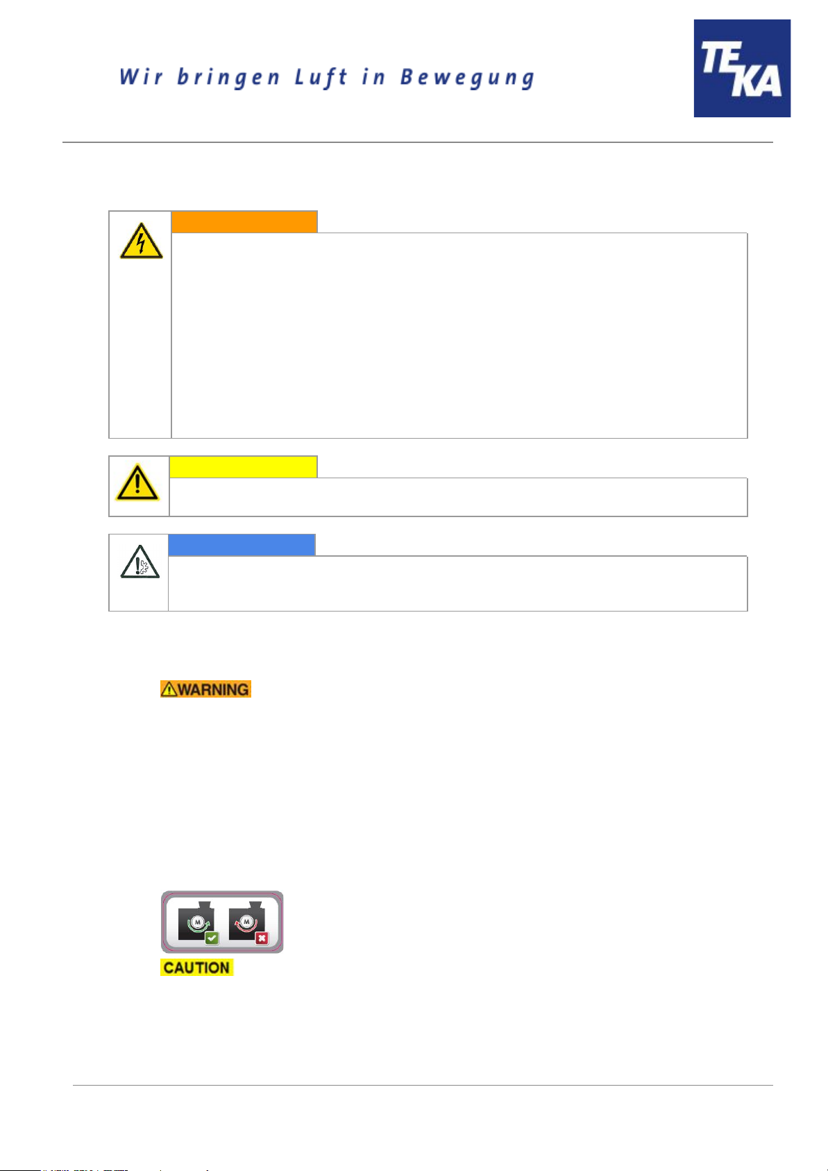
Dangers arising from fire.
In case of fire, if possible, switch the unit immediately off or disconnect it from the power
supply. Fire extinguishing measures which the operator is obliged to determine beforehand
must be initiated immediately.
The device is additionally equipped with a particle sensor, which can detect an increase of
the particles (eg due to fire, filter break, ...) within the device. The particle sensor thus
provides a monitoring of the particulate matter, but does not provide 100% protection for the
detection of a fire. When the particle sensor is triggered, the device switches off.
In the event of a fire the fire brigade has the possibility to fill the filter area with extinguishing
hose connection on the so-called C-pipe connection with extinguishing agent. The decision
about this has to be made exclusively by the fire brigade.
BA_Airtech_P10_IFA_190319_EN
6
19.03.2019

WARNING
Dangers arising from electricity.
The operator must ensure that electrical plants and equipment are only built, modified and
maintained by a qualified electrician or under the direction and supervision of a qualified
electrician. Do not work on components if you are not sure that these are disconnected. If
necessary, disconnect the device from the electric power supply and secure it against
unauthorized restarting.
4. Storage, transport and installation of the device
WARNING
Risk of injury from tilting or unmounted components when stored or transported.
The device must be secured against tilting and slipping when it is stored or transported. Do
not stand under or next to the floating load. Lift trucks, forklift trucks and transport cranes
must have a sufficient minimum load bearing capacity.
Dangers arising from titling or functional impairments at its destination.
The unit may only be set up on a suitable surface. The unit may only be set up on a suitable
surface. The surface must be vibration-free and horizontal. The operator must check the
bearing capacity of the surface. The unit must be secured on the surface, for example using
lag bolts or heavy-duty anchors.
NOTICE
Damage or functional impairment of the unit due to climatic influences.
The unit must be stored in a dry place and protected against moisture during transport. As a
matter of principle, the filter unit is not designed to be installed outdoors. In this case contact
the manufacturer in order to find out if a caping or a trace heating system are necessary.
BA_Airtech_P10_IFA_190319_EN
7
19.03.2019

● Set up the preassembled part of the filter unit (A). Use the 4 crane eyelets of the yellow
transport frame (B). The device must be safely fixed on the ground, e.g. with the help of lag
bolts or high load anchors.
The yellow transport frame must be dismantled after installing the filter unit.
● Fix the preassembled upper part (C) of the unit onto this part with the help of the screws
included in the delivery. You can lift it with the help of the forklift skids (D) located at the
connection cover.
● Adjust the ejection nozzles (E).
● Fix the intake ducts (F) to the extraction housing with the help of the assembly material included
in the delivery. The holes of the grid must be adjusted to the front.
As an option, intake elements can be used additionally to the intake ducts. They have to be
connected to the filter housing via piping.
BA_Airtech_P10_IFA_190319_EN
8
19.03.2019

5. Commissioning
WARNING
Dangers arising from a defective condition of the unit.
Make sure that the measures described in this chapter are completed before the
commissioning of the unit. All doors of the unit must be closed and all necessary connections
must be attached before turning the unit on. Do not operate the unit if any components are
defective, missing or damaged. Check the orderly condition of the unit before switching it on.
The unit must not be operated without a filter element.
NOTICE
Damaged supply lines.
Make sure that the supply lines are protected against damage by forklift trucks and similar
events. Protect all supply lines from heat, moisture, oil and sharp edges.
BA_Airtech_P10_IFA_190319_EN
9
19.03.2019

5.1. Electrical connection
WARNING
Risk of electric shock.
Electrical plants and equipment may only be built, modified and maintained by a qualified
electrician or under the direction and supervision of a qualified electrician. Do not work on
live electrical components and elements if you are not sure that these are indeed
disconnected. If necessary, disconnect the device from the mains. The operator is
responsible for a potential-free balance of the equipment.
If the unit is equipped with a frequency converter, then it may only be operated on networks
with an AC/DC sensitive RCCB. For frequency converter operation, the cross section of the
protective conductor
● must be at least 10mm²,
● and must be at least equal to the size of the operator side outer conductor
cross-section.
CAUTION
Health hazard arising from unintentional cleaning processes.
Switch on the control only if the unit is in operational condition.
NOTICE
Electric malfunction possible in cause of an incorrect power supply.
Pay attention to the admissible supply voltage. Please observe the specifications on the type
plate.
● Mount the housing of the external control (if it is not mounted on the device itself) close to the
device on the wall or at any other appropriate mounting point. Or mount the control together
with a cabinet console on a suitable surface, for example using lag bolts or heavy-duty anchors.
The housing is not suited for outdoor installation.
● Connect all visible cables and hoses are according to their functions. When delivered they are
labelled according to their functions. When connecting to the control, please observe the
specifications on the circuit diagram which is attached to the control.
● Connect the unit to the power supply.
● Check if the direction of fan rotation is correct. A wrong rotation direction can be identified
thanks to the sticker sticked to the fan scroll which is showing the direction. Compare the
rotation direction on the sticker to the rotation direction of the motor cooling fan when the motor
is running down after being switched off. If the motor rotates in the wrong direction, disconnect
the device from the power supply and exchange two phases at the supply line to the control.
When the fan rotates in the wrong direction, the extraction capacity is
reduced.
BA_Airtech_P10_IFA_190319_EN
10
19.03.2019

5.2. Precoating of the filter cartridges
For a longer service life of the filter cartridges we recommend to pretreat them with a filter aid (precoat).
The precoating can only be carried out during the commissioning at the operation site. When the
operator orders and installs new filter cartridges, we recommend to also precoat them before the
commissioning.
Please read and refer to "Precoating new filter cartridges" in the chapter "Maintenance". There
you can also find a description of the operating method of the precoat.
5.3. Connecting the compressed air supply
5.3.1. Compressed air supply for the cleaning of the filter cartridges
The filter cartridges of the system are automatically cleaned. Cleaning is carried out pneumatically via a
built-in compressed air tank.
Without compressed air supply the filter cartridges will become dirty very quickly.
● The external compressed air supply must be assured with an approved compressed air hose.
For the connection to the device, the compressed air hose must be equipped with a quick
coupling for an insert sleeve DN 7.2.
The compressed air must be dry and oil-free.
● The operating pressure of the compressed air supply must be a minimum of 3 bars and
maximum of 4 bars.
In case of the pressure being too low, the compressed air tank does not reach
quickly enough the operating pressure for the following cleaning. There is a risk of
material damage when the pressure is too high.
● Connect the compressed air hose to the insert sleeve (see chapter 2.1).
BA_Airtech_P10_IFA_190319_EN
11
19.03.2019

6. Operating the system
6.1. Explanation of the operating elements
Control functions, setting options for programs, menu navigation, error messages, etc. are
described in the enclosed operating manual of the unit control. There is also an explanation of the
elements of the control panel.
Operating elements for the device control
Representa
tion
Designation
Description / function
Main switch
●OFF: The device is disconnected from the power supply.
●ON: The device is connected to the power supply and ready to
operate.
The main switch also serves as an emergency off
switch.
Emergency stop
button
This button can be used to switch off the unit in an emergency.
When switched off, the unit is not de-energised.
The unit cannot be switched on again until the button has been
unlocked.
Operating elements for status and error messages
Representa
tion
Designation
Description / function
Stroboscope flash
The stroboscope flash draws attention to an error message of the
device control by flashing up. The error message is shown on the
display of the control.
Signal horn
Honking signals that the unit signals an error. Please refer to the error
message shown on the display of the control.
BA_Airtech_P10_IFA_190319_EN
12
19.03.2019

7. Maintenance
In accordance with national regulations, the operator is obliged to carry out repeat and functional tests.
Unless otherwise specified by national regulations, we recommend regular visual inspections and
functional tests of the device as described in the chapter “Maintenance intervals”.
You find the chapter “Maintenance intervals” at the end of the document. The general
maintenance (visual inspection, etc.) is also explained there.
In the chapter “Maintenance intervals” there is information on the maintenance intervals of the filter
elements. But these are only recommendations. Depending on the application (multi-shift operation,
dust generation, ...) it may be necessary for the operator to change the maintenance intervals.
In this chapter the maintenance work which is caused by wear caused during operation is described.
WARNING
Work on the open system entails the risk of electrical shock or accidental restart the
system. Both pose a danger to life and limb.
When cleaning and servicing equipment during the replacement of parts or when changing
to another function, set the device to maintenance condition first (see chapter “Reset to
maintenance state”).
A recommissioning of the device must only occur if it is ensured that the device is
functionally equivalent to the original state.
CAUTION
Hazards to the respiratory tracts are possible.
All maintenance work must only be carried out in well-ventilated rooms and
while wearing an appropriate respiratory mask! We recommend: respiratory
protection half mask DIN EN 141/143 protection level P3. For all maintenance
work ensure a cautious handling of filter elements and components in order to
avoid whirling up dust.
The operator is obliged to store and dispose of the collected dust in accordance with national or
regional regulations. For all maintenance or cleaning work please refer to the applying
environmental regulations. Pollutants and filter elements must be disposed of or stored according
to the regulations as well. If you have any doubts, we recommend contacting a disposal
contractor in your area.
BA_Airtech_P10_IFA_190319_EN
13
19.03.2019

7.1. Reset to maintenance state
● Switch off the unit. Then disconnect the unit from the power supply by setting the main switch in
the “OFF” position. Secure the unit against unauthorized restarting during maintenance.
● Disconnect the compressed air hose of the external compressed air supply from the insert
sleeve (see chapter 2.1).
● Empty the compressed air tank by opening the drain valve (see chapter 2.1) with a suitable
screwdriver. Minor quantities of condensation water can leak out when opening the drain valve.
Close the drain valve when the compressed air tank is entirely empty.
When opening the drain valve a compressed air blast can occur!
● After completion of all maintenance work the unit can be reconnected to the power supply and
the external compressed air supply.
7.2. Cleaning the filter cartridges
CAUTION
A sudden jet of compressed air and huge amounts of whirled up dust are possible
due to an automatic cleaning with an opened service door.
During the operation of the device, the service door of the filter housing must not be opened.
The same applies to the ready to operate condition (standby) as there is also the possibility
of an automatic cleaning (subsequent cleaning).
The filter cartridges are reusable filters and can be cleaned. The cleaning of the filter cartridges is
automatically carried out.
The degree of pollution of the filter cartridges is electronically monitored. In order to assure the required
extraction capacity of the device, the cleaning of the filter cartridges starts automatically when a preset
differential pressure value is reached. If the preset differential pressure value is not undercut after the
cleaning of the filter cartridges, another cleaning starts. The filter unit remains in operation during the
automatic cleaning. The compressed air blast is produced in opposite direction to the intake. The
cleaned dust falls downwards in the dust collecting tank.
Depending on the setting of the control unit there can be automatic postcleanings of the filter cartridges
even when the unit is switched off.
When the maximal admissible differential pressure value is reached, the device triggers an alarm (see
chapter “description of the control elements”). If despite of the automatic cleaning of the filter cartridge
the alarm value is not undercut anymore, the filter cartridge must be replaced. (see chapter: “Replacing
the filter cartridges”).
The differential pressure values in the control unit that initiate a cleaning or a filter alarm are preset
values adapted to the filter unit. Please find detailed information concerning the functioning in the
enclosed operating instructions of the control unit.
BA_Airtech_P10_IFA_190319_EN
14
19.03.2019

7.3. Replacing the filter cartridges
Replacing the filter cartridges becomes necessary when the filter cartridges are saturated with dirt in a
manner that despite of the cleaning the filter alarm is triggered again at very short intervals or
permanently. (The filter alarm is described in chapter “Cleaning the filter cartridges”.)
CAUTION
Whirling up dust is possible due to the polluted filter cartridges.
The filter cartridges must be cleaned before being replaced. This is done by carrying out 3
manual cleanings via the unit control (see separate operating instructions). The filter unit
must be switched off beforehand but without disconnecting the unit from the power supply.
After the cleaning, disconnect the filter unit from the power supply and secure it against
being switched on again. After cleaning the filter cartridges wait about 5 minutes before
opening the service door of the filter housing.
We recommend to pretreat new filter cartridges with filter aid (e.g. precoat) before the first
commissioning. Refer to the chapter "Precoating new filter cartridges".
● The changing of the filter cartridges must be carried out by two people.
● Before changing the filter cartridges hold ready an appropriate container (e.g. PE bag) for
disposal.
The polluted filter cartridges must be packed into an appropriate container
(e.g. PE bag). PE bags are optionally available (see list of spare parts)! We recommend
having disposal bags in stock.
● Open the service door of the filter cartridges.
BA_Airtech_P10_IFA_190319_EN
15
19.03.2019

● Resolve the clamping screw (pos. A) of the cartridge holder (pos. B) and slip the disposal bag
over the cartridge holder and the filter cartridge (pos. C).
● Hook off the cartridge holder from the cartridge guiding (pos. E) and take it out of the device
together with the filter cartridge and the disposal bag.
● Loosen the cylinder nut (pos. F) outside on the cartridge's bottom. Therefore do not touch the
cylinder nut directly with your hands, but grab it from the outside through the bag.
● Pull the cartridge holder out of the disposal bag past the filter cartridge without generating dust.
Take the displacer (pos. D) out of the filter cartridge without generating dust.
● Carefully close the disposal bag (e.g. with a cable fastener) and store or dispose of it together
with the polluted filter cartridge in an appropriate container according to the regulations.
● Insert the displacer into the new filter cartridge in a way that the screw of the displacer is put
through the hole of the cartridge's bottom. Fasten the displacer with the cylinder screw nut from
the outside.
● Push the new filter cartridge into the cartridge holder.
Only use TEKA spare filters. Otherwise the proper functioning of the unit is
not guaranteed.
● Fasten the clamping screw of the cartridge holder.
● Close the maintenance door.
BA_Airtech_P10_IFA_190319_EN
16
19.03.2019

7.4. Emptying the dust collecting tank
The dust collection container must be cleaned after a certain number of operating hours. This range
depends on the amount of dust. The dust collecting tank may only be filled up to a maximum of 25%.
The filling level has to be proofed at least once a week.
CAUTION
Whirling up dust is possible due to the polluted filter cartridges!
The filter cartridges must be cleaned before emptying the dust collecting tank.This is done
by carrying out 3 manual cleanings via the unit control (see separate operating
instructions).The filter unit must be switched off beforehand but without disconnecting the
unit from the power supply.After the cleaning, disconnect the filter unit from the power supply
and secure it against being switched on again.After cleaning the filter cartridges wait about 5
minutes before opening the service door.
Before emptying the dust collecting tank hold ready an appropriate container (e.g. PE bag). The
bags are optionally available at TEKA, see list of spare parts. We recommend having PE bags in
stock.
● Open the service door of the dust collecting housing (see chapter 2.1).
● Open the toggle levers (B) of the dust collecting tank (A).
Risk of contusion when opening the toggle levers.
● Carefully pull the dust collecting tank out of the housing.
● Remove the slip-on frame (C) from the dust collecting tank.
● Close the dust collection bag (e.g. with a cable fastener).
● Remove the dust collection bag and store or dispose of it according to the regulations.
● Place a new dust collection bag in the dust collection container so that the bag is put over the
edge of the dust collection container. Therefore place the slip-on frame back on the dust
collecting tank.
● Push the dust collecting tank back into the dust collecting housing.
● Close the toggle levers so that the dust collection container is pressed tightly against the above
chute.
● Close the service door.
BA_Airtech_P10_IFA_190319_EN
17
19.03.2019

7.5. Draining the condensate
Operation with compressed air can result in condensation water being gradually deposited in the
compressed air tank. The condensed water must be emptied regularly. The maintenance interval
depends heavily on the quality of the compressed air and cannot, therefore, be determined in advance.
CAUTION
When opening the drain valve a blast of compressed air is possible.
Open the drain valve slowly.
● Empty the compressed air tank by opening the drain valve (see chapter 2.1) with a suitable
screwdriver. Let the escaping condensate flow into a suitable container.
● Close the drain valve.
BA_Airtech_P10_IFA_190319_EN
18
19.03.2019

7.6. Precoating of new filter cartridges
Before the first commissioning new filter cartridges can be pre-treat with precoat consumable. The
precoat consumable assists against a "caking" of extracted particles on the filter surface and thus
prolongs the life of the new filter cartridge
Unlike with other maintenance work, this step must be carried out with the system switched on and
operating. This is necessary to allow the filter aid to disperse on the surface of the filter cartridges
through suction.
CAUTION
On contact the precoat consumable can be hazardous to the
respiratory tract and cause skin irritation or eye irritation.
Observe the listed manufacturer instructions provided:
Handling: Avoid the formation of dust!
Storage: Seal the container tightly before storage!
Respiratory protect: Dust mask without protection level!
Hand protection: Protective gloves in cloth, rubber or leather!
Eye protection: Safety glasses with side shields!
Body protection: Anti-static work shoes!
CAUTION
During operation of the device an automatic cleaning can take place. This involves the
risk of a sudden jet of high-pressure air and excessive dust formation at the point of
entry of the filter aid.
At first make sure that there is no compressed air in the compressed air tank. Please refer to
the chapter "Reset to factory settings". Before switching the device back on, disconnect the
compressed air hose from the device.
● Provide sufficient filter aid. We recommend using 10 grams for each square metre of the filter
surface. The filter aid is available at TEKA (see list of spare parts).
● Choose the capture point in the suction pipe that is the closest to the filter cartridges. E.g. an
inspection flap can be used as a capture point.
● Switch the device on.
● Let the filter aid bit by bit be sucked in via the capture point.
BA_Airtech_P10_IFA_190319_EN
19
19.03.2019

8. Dismantling / Disposal
Only authorised personnel may disassemble the machine.
WARNING
Dangers arising from electricity.
Before the dismantling of the machine it has to be disconnected from the power supply and
all supply lines.
CAUTION
Whirling up dust is possible due to the deposited dust.
During all work a suitable respiratory protection and protective clothing have to
be worn.
The operator is obliged to store and dispose of the collected dust in accordance with national or
regional regulations.
9. Diagnostics and troubleshooting
A list of possible system errors is provided in the table.
Error messages of the control unit are described in the enclosed operating manual of the control
unit.
Faults indicated by control elements are explained in the chapter “Description of the control
elements”.
A recommissioning of the device must only occur if it is ensured that the system is functionally
equivalent to the original state. Repairs may only be carried out by TEKA personnel or, after
consultation with TEKA GmbH, by the personnel authorised by the operator.
Adhere to the instructions in the chapter "Safety instructions" and " Maintenance" when carrying out any
repairs. If in doubt, contact our TEKA service department:
Tel: +49 2863-9282-0
Fault
Cause
Removal
System does not start.
Plug power supply is missing or
incorrectly inserted.
Plug connector check power
supply / plug in correctly.
No power at outlet.
Check the mains, remove error if
possible.
BA_Airtech_P10_IFA_190319_EN
20
19.03.2019
Other manuals for Airtech P10
1
Table of contents
Other Teka Fan manuals