THIS DOCUMENT CONTAINS PROPRIETARY INFORMATION OF TEKA ILLUMINATION AND ITS RECEIPT OR POSSESSION DOES NOT CONVEY ANY RIGHTS TO REPRODUCE, DISCLOSE ITS CONTENTS, OR TO MANUFACTURE, USE OR SELL ANYTHING IT MAY
DESCRIBE. REPRODUCTION, DISCLOSURE OR USE WITHOUT SPECIFIC WRITTEN AUTHORIZATION OF TEKA ILLUMINATION IS STRICTLY FORBIDDEN.
5/64” & 3/32” Allen Wrench
Waterproof Wire Connectors
Phillips Screwdriver
Mounting Hardware
Gloves
NEEDED
FOR
INSTALLATION:
By Others
This set of instructions
also works for:
DATE
5-3-18
REFERENCE NUMBER
INS-2523-00
40429 Brickyard Drive • Madera, CA 93636 • USA
559.438.5800 • FAX 559.438.5900
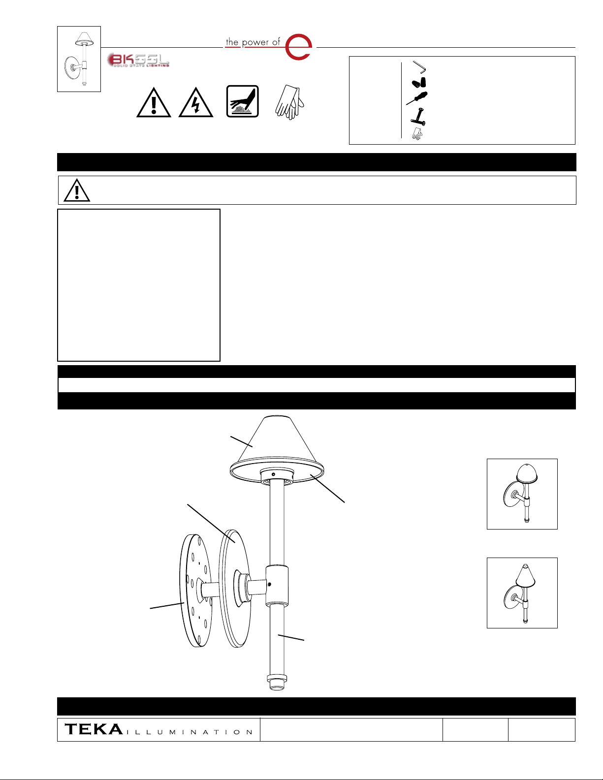
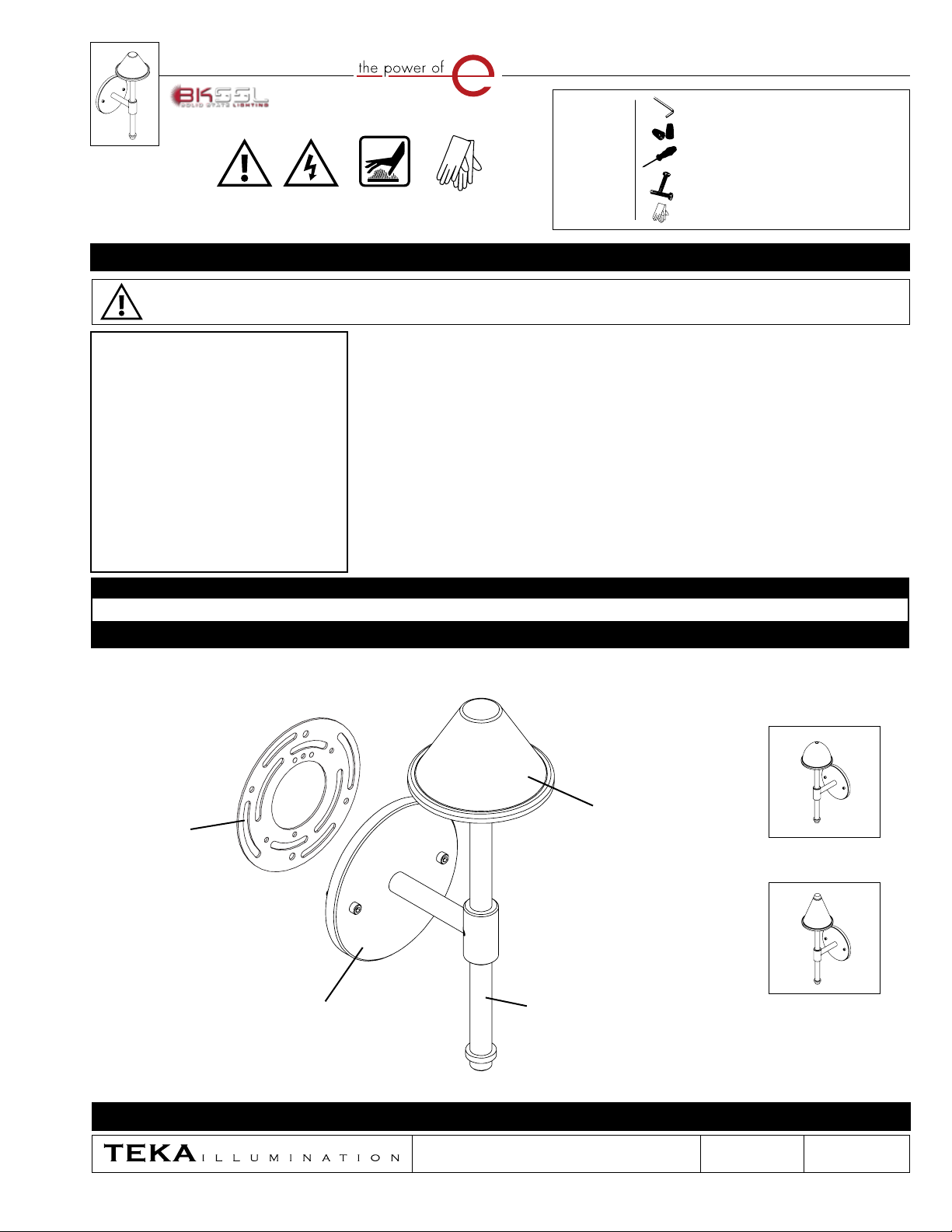
HIGH LIGHT WALL™ (HLW)
IMPORTANT SAFETY INFORMATION - READ, FOLLOW, AND SAVE THESE INSTALLATION INSTRUCTIONS
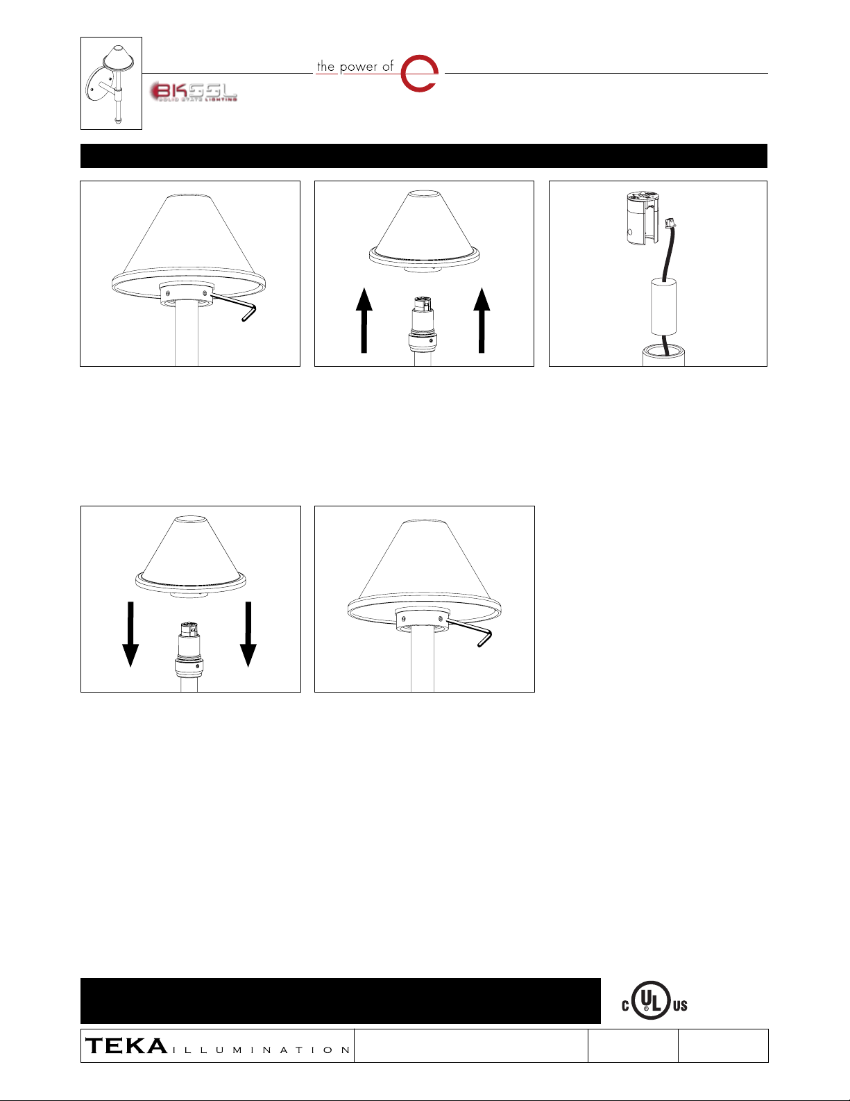
Canopy Stem
Universal
Mounting
Ring
Shade
B - Bali
C - Classic
M - Moor
Wear Gloves
Hot Surface
Warning Low Voltage
IMPORTANT - WEAR GLOVES TO AVOID GETTING FINGERPRINTS ON THIS PRODUCT. MANY TEKA ILLUMINATION PRODUCTS ARE DESIGNED TO NATURALLY PATINA.
OILS FROM YOUR SKIN WILL ACCELERATE THIS PROCESS WHERE TOUCHED AND ARE NEARLY IMPOSSIBLE TO REMOVE. THIS PROCESS OCCURS OVER TIME AND IS
DETERMINED BY THE INSTALLATION ENVIRONMENT.
· Suitable for wet locations
IMPORTANT LISTINGS AND CERTIFICATIONS
Please refer to the low voltage design guide at www.tekaillumination.com/lvguide before installation for proper wire selection.
IMPORTANT SAFETY INFORMATION - READ, FOLLOW, AND SAVE THESE INSTALLATION INSTRUCTIONS
• Product must be installed by a qualified person in a manner
consistent with its intended use and in compliance with the
National Electrical Code, Canadian Electrical Code, and all Local and
Provincial Codes.
• Follow product label information and instructions.
• Qualified Personnel with appropriate personal protective
equipment must perform all servicing of this product.
• Before wiring to power supply and during servicing, turn off and
lock out power at fuse or circuit breaker before service.
• The use of accessory equipment not recommended by the
manufacturer or installed contrary to instructions may cause an
unsafe condition. The use of damaged components may cause an
unsafe condition and void product warranty.
IMPORTANT SAFETY INFORMATION - READ, FOLLOW, AND SAVE ALL SAFETY
AND INSTALLATION INSTRUCTIONS
• Do not block light emanating from product in whole or part, as
this may cause an unsafe condition.
• Never operate the fixture with missing or damaged lens.
Lens must be cleaned on regular basis.
• Entire fixture may become extremely hot. Do not touch hot
lens or fixture body.
• Replace LED assembly only with correct wattage and type of
power supply appropriate for LED assembly.
• All gaskets, o-rings and sealing surfaces must be kept clean
during installation and service; failure to do this may cause an
unsafe condition and void product warranty.
INSTRUCTIONS PERTAINING TO
A RISK OF FIRE, OR INJURY TO
PERSONS IMPORTANT SAFETY
INSTRUCTIONS
Lighted fixture is HOT!
WARNING - To reduce the risk of
FIRE OR INJURY TO PERSONS:
Turn off/unplug and allow to cool before replacing LED.
Fixture gets HOT quickly! Contact only switch/plug when
turning on. Do not touch hot lens, guard, or enclosure.
Keep fixture away from materials that may burn.
Do not operate the luminaire fitting with a missing or
damaged shield. Do not touch the source at any time. Use
a soft cloth or gloves. Oil from skin may cause damage.
SAVE THESE INSTRUCTIONS
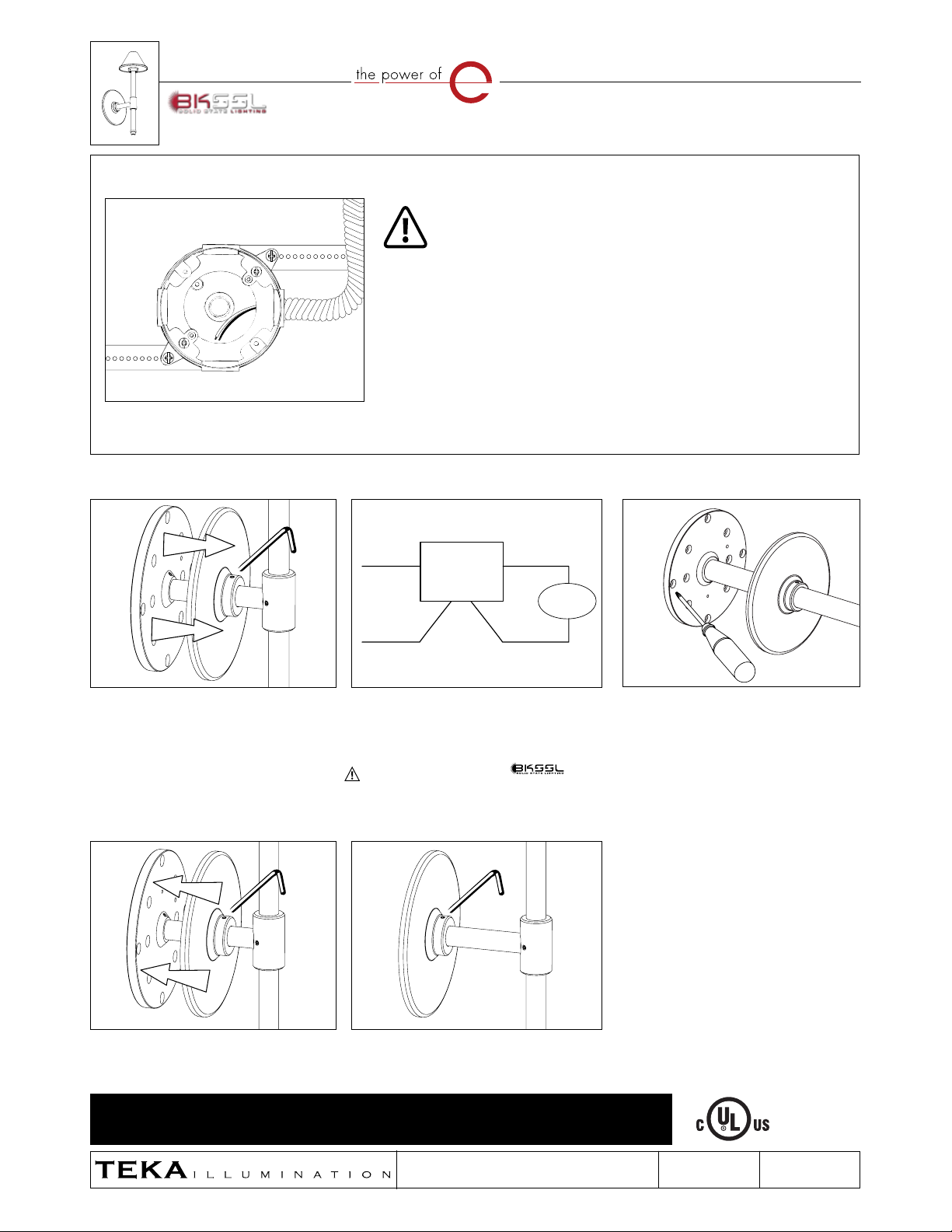
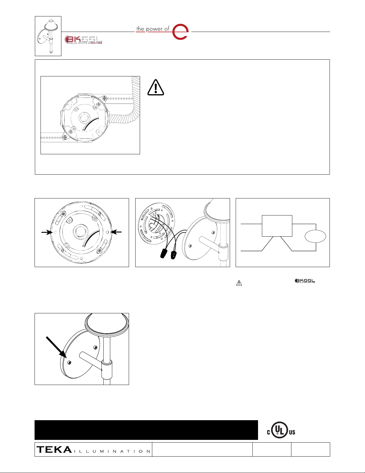
Standard Canopy Installation Instructions