Tekmar 153 User manual

Settings
Temperature Display — –85 to 302°F (–65 to 150°C)
Supply (1) Setpoint — –40 to 239°F (–40 to 115°C)
Throttling Range — 16 to 67°F (9 to 37°C)
Boiler Return (2) — –40 to 239°F (–40 to 115°C)
Temperature Scale — Fahrenheit/Celsius
Program settings — Ten year memory backup
Mixing Setpoint
Control 153
Floating Action
1
Supply (1) Throttling Return (2)
PRGM
FC
Item
Date
S/N
Power supply: 24V 60Hz 3VA
Relay capacity: 24V 10A
2
24V only
5
Close
No Power
678
Com
Sen
Sup
Sen
Ret
Sen
OC
34
CRR'
Open
1
2
Power
- Data Brochure
Mixing Setpoint Control 153 07/93
D 153
OC
FC
Throttling
Supply(1)
1
Return(2
Programming
mode indicator
Wiring Chamber;
Terminals for 24Vac
power supply and
control circuit
to actuating motor
Item selection and
display button
Relay operation
indicators
Item
Identifiers
Temperature and
Throttling range
Display
Wiring Chamber;
Terminals for
Sensor(s)
Technical specifications
Dimensions — 2-7/8" x 4-3/4" x 7/8"
(74 x 120 x 22 mm)
Gross Weight — 1 lb (450g)
Ambient — –20 to 120°F (–30 to 50°C)
< 90% RH non-condensing
Power supply — 20 to 28Vac, 60 Hz, 3VA,
class II transformer
Relay capacity — SPST, 24Vac, 10 amp resistive
Sensor — 10 kΩ@ 77°F (25 ±0.2°C),
curve 3, NTC thermistor
accurate with up to 500 ft.
(150m) of 18 gauge wire
Control accuracy — ±0.5°F ( ±0.3°C) at
70°F (21°C)
Hole for mounting screw
Sequence of Operation
• When the Mixing Setpoint Control 153 Floating Action is powered-up
the digital display will show all of the display elements. The
control will then monitor sensor Supply (1) temperature. If a Boiler Return (2) sensor is connected, pressing and releasing the
Item button will toggle the display between Supply (1) and Boiler Return (2) temperature readings.
Floating Action Operating Mode
•
If the relay Open (O) is constantly on,
the measured temperature is at least
1/2 the throttling range setting below the setpoint. The mixing valve should
be opening or fully opened because more heat is required.
•
If the relay Close (C) is constantly on,
the measured temperature is at least
1/2 the throttling range setting above the setpoint. The mixing valve should
be closing or fully closed.
•
FloatingActionoccurswhen
themeasuredtemperatureisbetweenthesetwo
points (Throttling range).
Technical Data
°C or °F
indicators
Programming and
display buttons
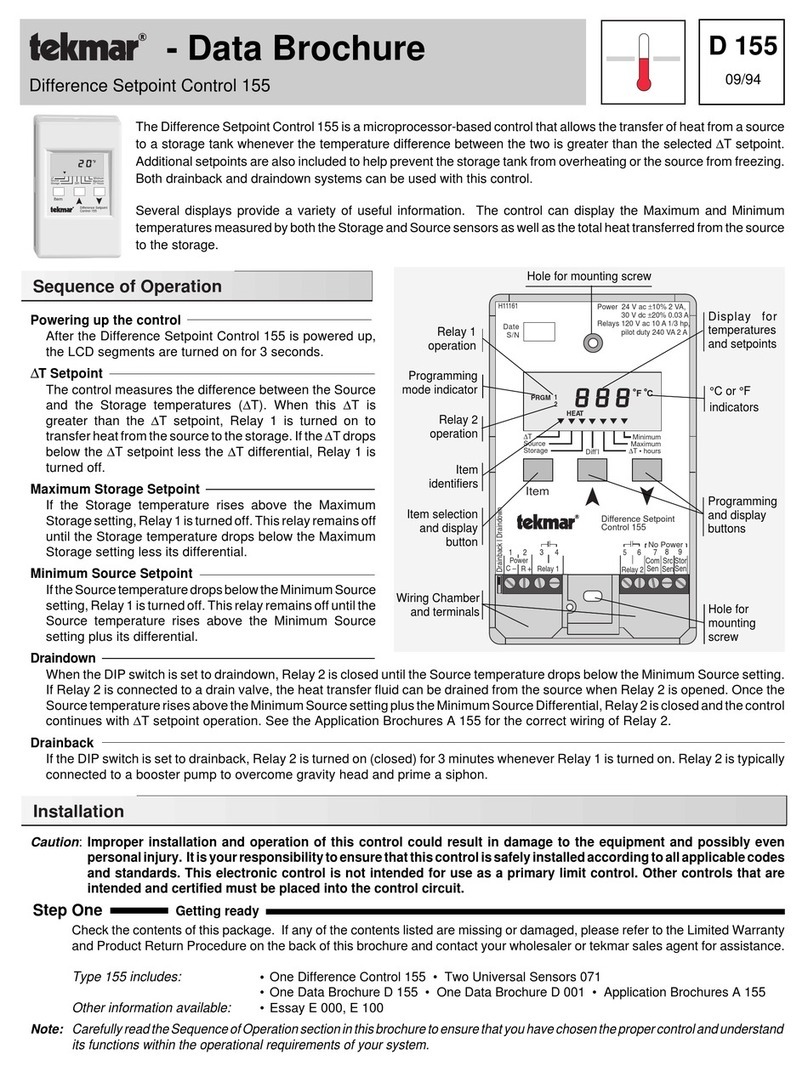
The tekmar Mixing Setpoint Control 153 is a microprocessor-based control with a floating action output
intended to operate a mixing valve, damper, etc. through an actuating motor.
This reliable and versatile control has an adjustable throttling range and a very wide setpoint range that
makesituseableinmanydifferentapplications. ThecontrolhasadigitalLCDwindowthatnormally
shows
the actual sensor temperature and can be used to view the setpoint and other programmed settings.
AUniversalSensor071issuppliedwiththecontrol. Thewiretothesensormaybeextendedforanylength
up to 500 ft. (150m) by standard 18 AWG low voltage wire. When an optional return sensor is added, a
minimum boiler return temperature can be constrained. The display will indicate a sensor fault whenever
the sensor is disconnected or short circuited, or the return sensor is short circuited.
OPEN RELAY ON
Temperature
Warmer
Cooler
Time
BOTH
RELAYS OFF;
NO VALVE
MOVEMENT
Desired
Temperature
Setting Throttling
Range
24 Vac Floating Action
CLOSE RELAY ON

•••
2
Installation
Caution
Improper installation and operation of this control could result in damage to equipment and possibly even personal
injury. It is your responsibility to ensure that this control is safely installed according to all applicable codes and
standards.
Step One Getting ready
Check the contents of this package. If any of the contents listed are missing or damaged, please refer to the Limited Warranty
and Product Return Procedure on the back of this brochure and contact your wholesaler or tekmar sales agent for assistance.
Type 153 includes:
•One Control 153 • One Universal Sensor 071
• One Data Brochure D 153 • One Data Brochure D 001
Other information available:
• Essay E 001
Note: Carefully read the Sequence of Operation section in this brochure to ensure that you have chosen the proper control and
understand its functions within the operational requirements of your system.
Step Two
Mounting
The control is mounted in accordance with the instructions in the Data Brochure D 001.
Step Three
Rough-in wiring
All electrical wiring terminates in the two wiring chambers at the bottom front of the control. If the control is to be mounted on
an electrical box, the wiring can be roughed-in at the electrical box prior to installation of the control (see Brochure D 001).
Standard 18 AWG solid wire is recommended for all low voltage wiring to this control.
Caution: Power should not be applied to any of the wires during this rough-in wiring stage.
• Install the Universal Sensor 071 according to the instructions in Data Brochure D 001 and run the wiring back to the control but
don’t connect.
• Install a 24Vac Class II transformer with a minimum 5 VA rating close to the control, and run the wiring from the transformer
to the control.
A Class II transformer must be used. Do not connect any of the transformer terminals to ground.
• Install the wiring from the actuating motor to the control.
Step Four
Testing and connecting the wiring
Caution
These tests are to be performed using standard testing practices and procedures and should only be carried out by
a properly trained and experienced technician.
Agoodquality electricaltestmeter, capable ofreadingfrom atleast0 —200Volts AC, andatleast 0—2,000,000 Ohms,
is essential to properly test this control.
At no time should voltages in excess of 28Vac be measured at any of the wires connected to this control.
Test the sensor
This test must be performed
before
power is applied to the control and
before
a sensor is connected to the terminal strip. Test
the sensor(s) according to the instructions printed in the enclosed Data Brochure D 001.
Supply and Boiler Return Sensor Operating Mode
• If a Boiler Return Sensor option is installed,
then whenever the measured boiler
return water temperature is near the return minimum, the control starts to close
the 4-way mixing valve in order to divert more hot water back to the boiler. The
Return(2)indicatorwillbeflashingataslowratetoindicatemixingvalveisbeing
controlled by the Boiler Return (2) sensor reading. When using a Boiler Return
(2) sensor for minimum boiler return protection, it is essential that there always
be water flow past the Boiler Return (2) sensor whenever there is Supply (1)
demand.
Supply Sensor Operating Mode
• If only a Supply Sensor is installed,
the control regulates the supply water temperature through applying a floating output signal
totheactuatingmotor. Supply(1)adjustmentsetsthesetpointtemperature. Adjustingthethrottlingrangewillsetthetemperature
range in which floating output action occurs.
Actuating
Motor 216
4-Way Valve
016 - 023
Heating System Boiler Return (2)
Sensor 071
Supply (1)
Sensor 071
M
153

3
Electrical connections
Power and output connections — Caution, Maximum 24 Volts A.C.
Connect — the transformer to terminals
C — R
(1 and 2)
— the floating output device circuit to terminal Relays:
Rl — Open (3 and 4)
Rl — Close (3 and 5)
Sensor connection — Caution, voltage is never applied to these terminals
Connect Supply (1) Sensor
071 to terminals
Sup Sen and Com Sen
(6 and 7)
Return (2) Sensor
071 to terminals
Ret Sen and Com Sen
(6 and 8)
Optional
Test the power supply
• Ensure that the wires from the power supply transformer are not touching each other, any other wires, or ground.
Turn on the
power and, using an AC voltmeter, you should measure between 20 and 28 volts at the secondary side of the transformer.
• Turn off the power and complete the electrical connections to the terminal strip of the control.
Settings
The digital display on the Mixing Setpoint Control 153 Floating Action has the following uses:
• To display the supply and return (if installed) temperature(s) during normal operating mode.
• To allow the user to check and program the various control settings.
• To display control operation. (“O” display element comes on when the Open relay turns on to drive the mixing valve open and “C”
display element comes on when the Close relay turns on to drive the mixing valve close.)
• To display sensor faults. Display will show “Err 1” when the Supply (1) sensor is either open circuited, short circuited or out of
temperature range. Display will show “Err 2” when Boiler Return (2) sensor is short circuited.
The following diagram illustrates how to operate the keypad buttons in order to view settings and program the control.
OC
OC
OC
OC
Item
Item
Push or to
change Throttling Range
The control automatically goes back to operating mode when the buttons are left alone for 20 secondsThe control automatically goes back to operating mode when the buttons are left alone for 20 seconds
Push or to
change Return (2) Setpoint
Push or to
change Supply (1) Setpoint
DISPLAY MODE
During operation
, the open
(O) and close (C) pointers
indicate relay action.
If the Return (2) pointer
is
slowly flashing, the relay
operation is being controlled
by the return sensor
readings.
When the control is
powered-up, all display
elements turn on.
POWER ON
When in operating mode,
the Supply (1) temperature
will be displayed.
After approximately 5 seconds, the control
automatically goes into operating mode.
OPERATING MODE
PROGRAM MODE
Return (2)
Return (2)
Push and Release
the
"Item" button. The display
will toggle between Supply
(1) and Return (2)
temperature readings.
(When return sensor is
in use.)
Return (2)
Return (2)
Push and Hold
the "Item"
button. The programmed
Supply (1) setpoint will be
displayed.
Item
Supply (1)
1
Push and Hold
the
button. The programmed
Throttling range will be
displayed.
Push and Hold
the
button. The programmed
Return (2) minimum will be
displayed.
F
PRGM
F
Supply (1)
1
Item
Push all three buttons
at the
same time.
"PRGM 1" will
appear and the Supply (1)
pointer will flash. The control
will be in programming mode.
Throttling
F
Return (2)
F
2
Item
FC
Throttling
PRGM
Supply (1)
FC
FC
Throttling
Supply (1)
FC
Throttling
Supply (1)
1
2
1
1
2
Item
Pushing the "Item" button
changes the flashing
pointer to Throttling.
Item
Pushing the "Item" button
changes the flashing
pointer to Return (2).
Return (2)
F
2
PRGM
Item
PRGM
F
Push or to select between
Fahrenheit or Celsius scales
Item
Pushing the "Item" button
allows the Fahrenheit or
Celsius scale to be
selected.
C
PRGM
Throttling
F
Max. 24 Volts
Do not apply
power here
24Vac
power
supply
24Vac
power
supply
1
C
2
R
34
10A
5
R'
10A
Close
Open
6
Sup
Sen
Ret
Sen
78
Supply
Sensor
#1 (071) Return
Sensor
#2 (071)
Com
Sen
Power
Actuating Motor
Opens/Closes to operate
Mixing Valve, Damper, etc.

Before you leave
• Install the wiring cover over the wiring chamber and secure it with the screw provided. • Place the front cover on the control to
coverthesettingdialsandsnapitintoplace. • Placethisbrochure,andallotherbrochuresrelatingtotheinstallation,intheprotective
plasticbagsuppliedwiththecontrol. • Placethebaginaconspicuouslocationnearthecontrolforfuturereference. • Itisimportant
to explain the operation of this control within the system to the end user, and anyone else who may be operating the system.
In North America: tekmar Control Systems Ltd., Canada
tekmar Control Systems, Inc., U.S.A.
Head office: 4611 - 23rd Street
Vernon, B.C. Canada V1T 4K7
Tel. (604) 545-7749 Fax. (604) 545-0650
All specifications are subject to change without notice.
Printed in Canada on recycled paper.
Product designs and literature are Copyright © 1993 by:
tekmar Control Systems Ltd. and tekmar Control Systems, Inc. 4
Limited Warranty: tekmar warrants to the original purchaser each tekmar product
againstdefectsin workmanship and materials when the product is installed and used
incompliancewithtekmar'sinstructions. Thislimitedwarrantycoversthecostofparts
and labour provided by tekmar to correct defects in materials and/or workmanship.
Returned products that are fully operational are not considered a warranty case.
tekmaralsodoesnotcoverpartsorlabourtoremove, transportor reinstalla defective
product. tekmar will not be liable for any damage other than repair or replacement of
the defective part or parts and such repair or replacement shall be deemed to be the
sole remedy from tekmar. This warranty shall not apply to any defects caused or
repairs required as a result of unreasonable or negligent use, neglect, accident,
improper installation, or unauthorized repair or alterations. In case of defect,
malfunction or failure to conform to warranty, tekmar will, for a warranty period of 24
months from the date of invoice to the original purchaser or 12 months from the date
ofinstallationofthe product,whichever occursfirst,repair,exchangeor givecredit for
thedefectiveproduct. Anyexpressorimpliedwarrantywhichthepurchasermayhave,
includingmerchantabilityand fitnessforaparticularpurpose,shallnotextendbeyond
24 months from the date of invoice or 12 months from the date of installation of the
product, whichever occurs first.
Replacements: tekmar can send replacement products if requested. All replace-
ments are invoiced. Any possible credit for the replacement will only be issued once
the replaced product has been returned to tekmar.
Product Return Procedure: Products that are believed to have failed must be
returnedtotekmarControl Systems Ltd. 4611-23rd Street, Vernon B.C. Canada V1T 4K7
whenagreedtoby tekmar. The installeror otherqualified servicepersonmust,atthe
owner's expense, determine which component has failed. The product must be
returned complete with all of its components (sensors, base, etc.). Products must be
returnedtogetherwiththeproof ofpurchase tothe originalpurchaser whothenreturns
theproducttotekmarafterreceivingaReturnGoodsAuthorization(RGA)numberfrom
tekmar.
Please include the following information with the product. The full address of the
original purchaser, the RGA number and a description of the problem.
Fromthe U.S.A.,inorder toavoid customs charges,products mustbereturned viaUS
Post with the package clearly marked with the RGA number, product type and the
statement "Canadian Product returned for repair". For shipping purposes the product
can be valued at one half list price.
1) If returned during the warranty period and the product is defective,
tekmar will issue full credit for the returned product less cost of missing parts.
2) If returned during the warranty period and the product is fully operational, tekmar
willreturntheproducttotheoriginalpurchaserforatestingcostof$30.00pluspostage.
3) If returned during the warranty period and the product is not damaged and is fully
operational, tekmar can take back the product for a return charge of 40% of the
product's net value. This request has to be specified otherwise the product will be
returned with a testing cost of $30.00 plus postage.
4) If returned after the warranty period and the product needs repair, tekmar will
repair and return the product. Repair and postage costs will be invoiced. tekmar's
repaircostsarecalculatedat$30.00/hourplusthecostofparts. Iftherepaircostswill
be more than $60.00 a repair estimate will be sent to the original purchaser.
Testing and Troubleshooting
IftroubleshootingbecomesnecessarywiththeMixingSetpointControl153,followthetestingprocedureinstepfouroftheinstallation
procedure on page 2 of this brochure.
Ifthedisplaywindowshows"Err1",theSupply(1)sensoriseitheropencircuited,shortcircuited,orthesensortemperatureisoutside
the temperature range of the control. If this type of fault occurs, the control will run the mixing valve fully closed.
Ifthedisplaywindowshows“Err2”theBoilerReturn(2)sensorisshortcircuited,thecontroloperatesasifnoreturnsensorisinstalled.
Ifthe Boiler Return (2) sensorisconnected,butprogramming or Return (2)temperaturedisplaysdonot function, the sensoriseither
open circuited or colder than -85 °F (-65 °C).
If you do not think the control is operating properly, check to see that the settings have been made correctly and that the problem is
not a result of external causes. Make sure that all wiring connections are solid and the sensor(s) is located in the correct location.
Throttling Range
Setting the Throttling range on any control depends entirely on the actual operating characteristics of the mixing device and the load
in each specific application. Experience plus trial and error during actual operating conditions is usually the way most installers
determinethecorrectsetting. ForatekmarActuatingmotor,atypicalsettingis28°F(15°C). Fastermotorsrequirealargerthrottling
range.
Return (2)
The Return (2) setting provides a method to constrain the temperature of water returning to a boiler from a 4-way mixing valve. This
setting should be adjusted to the lowest return temperature that the boiler is rated for. When the boiler return water temperature
becomes too cold, the mixing valve is closed until the temperature is hotter than the Return (2) setting.
Limited Warranty and Product Return Procedure
Other Tekmar Controllers manuals

Tekmar
Tekmar D 650 User manual

Tekmar
Tekmar 284 Use and care manual

Tekmar
Tekmar D 255 User manual

Tekmar
Tekmar 274 User manual

Tekmar
Tekmar Mixing Control 356 User manual

Tekmar
Tekmar tekmarNet 4 Setpoint Control 162 User manual

Tekmar
Tekmar Snow Melting Control 680 Use and care manual

Tekmar
Tekmar Mixing Control 354 User manual

Tekmar
Tekmar 284 User manual

Tekmar
Tekmar tekmarNet 4 Setpoint Control 161 User manual
Popular Controllers manuals by other brands

Carel
Carel ir33+ quick start guide

Burkert
Burkert 8756 BATCH operating instructions

Honeywell
Honeywell HercuLine 10260A Installation, operation and maintenance manual

Parker
Parker 890CS product manual

Aube Technologies
Aube Technologies TH146-N-2H1C installation guide

M-system
M-system M8BS2-081 instruction manual