manuals.online logo
Brands
  1. Home
  2. •
  3. Brands
  4. •
  5. Tekmar
  6. •
  7. Controllers
  8. •
  9. Tekmar 155 User manual

Tekmar 155 User manual

09/94
D 155
TheDifferenceSetpointControl155isamicroprocessor-basedcontrolthatallowsthetransferofheatfromasource
to a storage tank whenever the temperature difference between the two is greater than the selected ∆T setpoint.
Additional setpoints are also included to help prevent the storage tank from overheating or the source from freezing.
Both drainback and draindown systems can be used with this control.
Several displays provide a variety of useful information. The control can display the Maximum and Minimum
temperaturesmeasuredbyboththeStorageandSourcesensorsaswellasthetotalheattransferredfromthesource
to the storage.
Difference Setpoint
Control 155
∆T
Source
Storage Diff’l
Minimum
Maximum
∆T • hours
PRGM
HEAT
FC
Item
Date
S/N
Power 24 V ac ±10% 2 VA,
30 V dc ±20% 0.03 A
Relays 120 V ac 10 A1/3 hp,
pilot duty 240 VA 2A
5
Relay 2
Drainback l Draindown
6
34
Relay 1
No Power
789
Com
Sen
Src
Sen
Stor
Sen
1
2
21
C – R +
Power
H11161
Sequence of Operation
Item selection
and display
button
Item
identifiers
Display for
temperatures
and setpoints
Programming
and display
buttons
Hole for mounting screw
°C or °F
indicators
Relay 2
operation
Hole for
mounting
screw
Wiring Chamber
and terminals
Programming
mode indicator
Relay 1
operation
Powering up the control
After the Difference Setpoint Control 155 is powered up,
the LCD segments are turned on for 3 seconds.
∆T Setpoint
The control measures the difference between the Source
and the Storage temperatures (∆T). When this ∆T is
greater than the ∆T setpoint, Relay 1 is turned on to
transferheatfromthesourcetothestorage.Ifthe∆Tdrops
below the ∆T setpoint less the ∆T differential, Relay 1 is
turned off.
Maximum Storage Setpoint
If the Storage temperature rises above the Maximum
Storagesetting,Relay1isturnedoff.Thisrelayremainsoff
until the Storage temperature drops below the Maximum
Storage setting less its differential.
Minimum Source Setpoint
IftheSourcetemperaturedropsbelowtheMinimumSource
setting,Relay1isturnedoff.Thisrelayremainsoffuntilthe
Source temperature rises above the Minimum Source
setting plus its differential.
Draindown
Whenthe DIP switch issetto draindown, Relay 2isclosed until the Source temperaturedropsbelow the Minimum Sourcesetting.
If Relay 2 is connected to a drain valve, the heat transfer fluid can be drained from the source when Relay 2 is opened. Once the
SourcetemperaturerisesabovetheMinimumSourcesettingplustheMinimumSourceDifferential,Relay2isclosedandthecontrol
continues with ∆T setpoint operation. See the Application Brochures A 155 for the correct wiring of Relay 2.
Drainback
If the DIP switch is set to drainback, Relay 2 is turned on (closed) for 3 minutes whenever Relay 1 is turned on. Relay 2 is typically
connected to a booster pump to overcome gravity head and prime a siphon.
Installation
Caution
:Improper installation and operation of this control could result in damage to the equipment and possibly even
personalinjury. Itisyourresponsibilitytoensurethatthiscontrolissafelyinstalledaccordingtoallapplicablecodes
and standards. This electronic control is not intended for use as a primary limit control. Other controls that are
intended and certified must be placed into the control circuit.
Step One Getting ready
Check the contents of this package. If any of the contents listed are missing or damaged, please refer to the Limited Warranty
and Product Return Procedure on the back of this brochure and contact your wholesaler or tekmar sales agent for assistance.
Type 155 includes:
•One Difference Control 155 • Two Universal Sensors 071
• One Data Brochure D 155 • One Data Brochure D 001 • Application Brochures A 155
Other information available:
• Essay E 000, E 100
Note: CarefullyreadtheSequenceofOperationsectioninthisbrochuretoensurethatyouhavechosenthepropercontrolandunderstand
its functions within the operational requirements of your system.
Difference Setpoint Control 155
- Data Brochure
Diff'l
F
∆T
Source
Storage
Minimum
Maximum
∆T •hours
Difference Setpoint
Control 155
Item
2
Step Two
Mounting
The control is mounted in accordance with the instructions in the Data Brochure D 001.
Step Three
Rough-in wiring
All electrical wiring terminates in the two wiring chambers at the bottom front of the control. If the control is to be mounted on
an electrical box, the wiring can be roughed-in at the electrical box prior to installation of the control (see Brochure D 001).
Standard 18 AWG solid wire is recommended for all low voltage wiring to this control.
Power should not be applied to any of the wires during the rough-in wiring stage.
• Install the Source and Storage Sensors 071 according to the instructions in Data Brochure D 001 and run the wiring back to the
control. Do not connect the wires to the terminals yet.
•EITHER: Installa24VacClassIItransformerwithaminimum5VAratingandrunthewiringfromthetransformertothecontrol.
A Class II transformer must be used.
Do not connect either of the transformer secondary wires to ground.
OR: Install a 30 V dc source and run the wiring back to the control.
• Run wiring back to the control from the devices connected to Relay 1 and Relay 2.
Step Four
Testing and connecting the wiring
Caution Thesetestsaretobeperformedusingstandardtestingpracticesandproceduresandshouldonlybecarriedoutbyproperly
trainedand experienced persons.Agood quality electrical testmeter,capable of readingfromat least 0 — 200Volts,and
at least 0 — 2,000,000 Ohms, is essential to properly test this control. At no time should voltages in excess of 28 V ac or
36 V dc be measured at any of the wires connected to the control.
Test the sensors
• This test must be performed
before
power is applied to the control and
before
the sensors are connected to the terminal strip.
Test the sensors according to the instructions in the enclosed Data Brochure D 001.
Test the power supply
• Ensure exposed wires are not grounded or in contact with other wires, then turn on the power supply. If a 24 V ac transformer
is used, make sure the voltmeter is set to AC. With the voltmeter leads connected to the secondary side of the transformer, you
shouldmeasurebetween20and28Vac.IfaDCpowersupplyisused,makesurethevoltmeterissettoDC.Connectthepositive
leadfromthevoltmetertothepositiveterminalontheDCsourceandthenegativeleadfromthevoltmetertothenegativeterminal
on the DC source. The voltmeter should measure between 24 and 36 V dc.
• Turn off the power and complete the electrical connections to the terminal strip of the control.
Power and output connections
The installer should test to confirm that no voltage is present at any of the wires.
•EITHER: Connect the 24 V ac power supply to terminals
Power
C- and R+
(1 and 2)
OR:Connect the negative (-) lead from the 30 V dc source to the Power C- terminal
Connect the positive (+) lead from the 30 V dc source to the Power R+ terminal
Note: The control will not operate if the DC leads are reversed.
• Connect the Relay 1 controlled device to terminals
Relay1
(3 and 4)
• Connect the Relay 2 controlled device to terminals
Relay 2
(5 and 6)
Sensor connections — Caution, voltage is never applied to these terminals
• Connect the Source Sensor
071 to terminals
Com Sen and Src Sen
(7 and 8)
• Connect the Storage Sensor
071 to terminals
Com Sen and Stor Sen
(7 and 9)
Do not apply
power here
24 V ac
or 30 V dc
power
supply
Relay 1 closes to
transfer heat
from the source
to the storage
Relay 2 closes to
satisfy drainback
or draindown
requirements
1
C-
2
R+
34
10A 10A
Relay 1 Relay 2
567
Com
Sen Src
Sen
Stor
Sen
89
Source
Sensor
071 Storage
Sensor
071
Power
Settings
Note: The control automatically
exits programming when
the buttons are left alone
for 20 seconds.
Use the arrow
keys to set the
“∆T Differential”.
Press and Release
the “Item” button to
change the display to
the “∆T Differential”.
Press and Release
the “Item” button to
change the display to
the “Minimum Source
Setpoint”.
Use the arrow
keys to set the
“Minimum
Source
Setpoint”.
Press and Release
the “Item” button to
change the display to
the “Minimum Source
Differential”.
Use the arrow
keys to set the
“Minimum Source
Differential”.
Press and Release
the “Item” button to
change the display to
“°F” or “°C”.
Use the arrow
keys to switch
between “°F”
and “°C”.
Use the arrow
keys to set the
“∆T setpoint”.
PROGRAMMING
Press and Hold
all
three buttons at the
same time to begin
programming. The first
item displayed is the
“∆T setpoint”.
Press and Release
the “Item” button to
change the display to
the “Maximum Storage
Setpoint”.
Use the arrow
keys to set the
“Maximum
Storage
Setpoint”.
Press and Release
the “Item” button to
change the display to
the “Maximum Storage
Differential”.
Use the arrow
keys to set the
“Maximum
Storage
Differential”.
Diff'l
PRGM
F
∆T
Source
Storage
Minimum
Maximum
∆T • hours Diff'l
PRGM
F
∆T
Source
Storage
Minimum
Maximum
∆T • hours Diff'l
PRGM
F
∆T
Source
Storage
Minimum
Maximum
∆T • hours Diff'l
PRGM
F
∆T
Source
Storage
Minimum
Maximum
∆T • hours
Diff'l
PRGM
∆T
Source
Storage
Minimum
Maximum
∆T • hours
F
Diff'l
PRGM
F
∆T
Source
Storage
Minimum
Maximum
∆T • hours Diff'l
PRGM
F
∆T
Source
Storage
Minimum
Maximum
∆T • hours
Item
Item
Item
Item Item Item
Item Item
Item
Item Item
Item Item
Item
∆T Setpoint. If the difference between the Source and Storage temperatures (∆T) is greater than this setpoint, Relay 1 is turned on and
heat is transferred from the source to the storage.
∆T Differential. This differential setting is used to prevent short cycling of the heat transfer device when the ∆T is near the ∆T setpoint.
Maximum Storage Setpoint. If the Storage temperature rises above this setpoint, Relay 1 is turned off.
Maximum Storage Differential. This differential setting is used to prevent short cycling of the heat transfer device when the Storage
temperature is near the Maximum Storage setpoint.
Minimum Source Setpoint. If the Source temperature drops below this setpoint, Relay 1 is turned off and Relay 2 operates according
to the requirements of the Draindown or Drainback system.
Minimum Source Differential. This differential setting is used to prevent short cycling of the heat transfer device when the Source
temperature is near the Minimum Source Setpoint.
Press and Release
the “Item”
button to view the current
“Source” temperature.
When the control is powered-up,
all LCD segments are turned on
for 3 seconds.
The current “∆T” is then
displayed. If Relay 1 is closed,
a “1” and the word “HEAT” is
displayed. If Relay 2 is closed,
a “2” is displayed.
Press and Release
the “Item”
button to view the current
“Storage” temperature.
Press and Hold
the
“Item” button to view
the “∆T” setpoint.
Press and Hold
the
“Up” button to view
the “Minimum Source”
setpoint.
Press and Hold
the
“Down” button to view
the “Maximum Storage”
setpoint.
Press and Release
the “Item” button to
view the “Maximum
Source” temperature
measured since this
display was cleared.
Press and Release
the “Item” button to
view the “Minimum
Source” temperature
measured since this
display was cleared.
Press and Release
the “Item” button to
view the “∆T•hours”.
The numbers shown
to the right indicate
5225 °F•hours.
The above Maximum or Minimum displays can be
reset by the following:
Press and Release
the “Item” button to
view the “Maximum
Storage” temperature
measured since this
display was cleared.
Press and Release
the “Item” button to
view the “Minimum
Storage” temperature
measured since this
display was cleared.
DISPLAY OPERATION
Note: The control changes from the above displays to the ∆T display if the buttons are left alone for 20 seconds.
Resetting Maximum or Minimum DisplaysViewing programmed setpoints
While the control is displaying any of the current sensor
measurements, the setpoints can be viewed by the following:
Item
Item
Item
Item
Item
Item
Item
Item
Diff'l
F
∆T
Source
Storage
Minimum
Maximum
∆T • hours
Diff'l
F
∆T
Source
Storage
Minimum
Maximum
∆T • hours
Diff'l
F
∆T
Source
Storage
Minimum
Maximum
∆T • hours
Diff'l
F
∆T
Source
Storage
Minimum
Maximum
∆T • hours
Diff'l
∆T
Source
Storage
Minimum
Maximum
∆T • hours
thousands
Diff'l
∆T
Source
Storage
Minimum
Maximum
∆T • hours
units
F
Diff'l
F
∆T
Source
Storage
Minimum
Maximum
∆T • hours Diff'l
F
∆T
Source
Storage
Minimum
Maximum
∆T • hours
Item Item
Diff'l
F
∆T
Source
Storage
Minimum
Maximum
∆T • hours Diff'l
∆T
Source
Storage
Minimum
Maximum
∆T • hours
Diff'l
F
∆T
Source
Storage
Minimum
Maximum
∆T • hours
1
HEAT
2
Diff'l
F
Minimum
Maximum
∆T • hours
1
∆T
Source
Storage
HEAT
2
Diff'l
F
∆T
Source
Storage
Minimum
Maximum
∆T • hours
1
HEAT
2
Diff'l
PRGM
FC
∆T
Source
Storage
Minimum
Maximum
∆T • hours
1
2
HEAT
Item
Press and Hold
the “Up” and
“Down” buttons for 1 second. The
word “Clr” is displayed and the value
is reset to the current sensor
measurement.
3
Source temperature is the temperature measured by the Source Sensor.
Storage temperature is the temperature measured by the Storage Sensor.
∆T is the calculated difference between the Source and Storage temperatures.
Maximum Source is the Maximum temperature measured by the Source Sensor since this item was last cleared.
Minimum Source is the Minimum temperature measured by the Source Sensor since this item was last cleared.
Maximum Storage is the Maximum temperature measured by the Storage Sensor since this item was last cleared.
Minimum Storage is the Minimum temperature measured by the Storage Sensor since this item was last cleared.
Energy Transfer (∆T•hours). This display allows the user to estimate the amount of energy transferred from the source to the storage.
The energy transfer is displayed by alternating between two numbers. When the °C or °F segment is off, the thousands are displayed.
Whenthe°Cor°Fsegmentison,theunitsaredisplayed.Theenergytransfercanbeestimatedbymultiplyingthe∆T•hoursbythesystem
flow rate (in US GPM) and by the constant K given in the adjacent table.
Example Energy Transfer = ∆T •hours x System flow x K
∆T• hrs = 005 (thousands) 225 °F (units) = 5225 °F •hours
System flow = 20 US GPM
Fluid = 20% glycol & 80% water, therefore K = 487
Energy Transfer = 5225 x 20 x 487 = 50,892,000 BTU
Freezing
point
32°F
25°F
15°F
3°F
-13°F
-35°F
K
@ 10°F
500
496
487
477
462
439
% Glycol by
weight
0%
10%
20%
30%
40%
50%
Kvaluesarecalculated
averages for most eth-
ylene glycol solutions
at 50°F (10°C). K in-
creases with higher
temperatures.
Difference Setpoint Control 155
Literature — D 155, A155, D 001, E 000, E 100
Control — Microprocessor control; This is not a safety (limit) control.
Packaged weight — 1.0 lb. (450 g), Enclosure C, PVC plastic
Dimensions — 4-3/4” H x 2-7/8” W x 7/8” D (120 x 74 x 22 mm)
Approvals — Meets DOC regulations for EMI/RFI.
Ambient conditions — Indoor use only, -20 to 120°F (-30 to 50°C), < 90% RH non-
condensing.
Power supply — Class 2, 24 V ac ±10% 2 VA OR 30 V dc ±20% 0.03 A
Relays — 120 V ac 10 A 1/3 hp, pilot duty 240 VA 2A
Sensors — NTC thermistor, 10 kW @ 25°C ±0.2°C ß=3892
included: Two of Universal Sensor 071.
Control accuracy — ±0.5°F (±0.25°C) with up to 1000 feet (300m) of 18AWG wire
to sensors.
∆
T Setpoint
— 2 to 90°F (1 to 50°C)
∆
T Differential
— 2 to 45°F (1 to 25°C)
Minimum Source
— -22 to 185°F (-30 to 85°C)
Min. Source Diff’l
— 2 to 45°F (1 to 25°C)
Maximum Storage
— -4 to 248°F (-20 to 120°C)
Max. Storage Diff’l
— 2 to 45°F (1 to 25°C)
In North America: tekmar Control Systems Ltd., Canada
tekmar Control Systems, Inc., U.S.A.
Head office: 4611 - 23rd Street
Vernon, B.C. Canada V1T 4K7
Tel. (604) 545-7749 Fax. (604) 545-0650
4
Step Five
Troubleshooting
Firstobservethesystemoperatingparameters.Thesourceoftheproblemcanoftenbeidentifiedbynotingadisplayitemwhichseems
unreasonable. Observing what the control is doing, and understanding the sequence of operation greatly aids in troubleshooting.
Ifthereisasensorfault,thecontroldisplaysanerrormessage.Usetheerrormessagetableprovidedbelowtodeterminewhichcircuit
has the fault and then refer to Step Four for testing of the wiring and sensors.
Diff'l
∆T
Source
Storage
Minimum
Maximum
∆T • hours
Storage Sensor Open/Short Circuit
The display flashes “Err” and the
“Storage” pointer. Both relays are
kept off with this error.
Source Sensor Open/Short Circuit
The display flashes “Err” and the
“Source” pointer. Both relays are kept
off with this error.
Diff'l
∆T
Source
Storage
Minimum
Maximum
∆T • hours
Product designs, software and literature are Copyright © 1994 by:
tekmar Control Systems Ltd. and tekmar Control Systems, Inc. All specifications are subject to change without notice.
Printed in Canada on recycled paper.
Difference Setpoint
Control 155
∆T
Source
Storage Diff’l
Minimum
Maximum
∆T •hours
PRGM
HEAT
FC
Item
Date
S/N
Power 24 V ac ±10% 2 VA,
30 V dc ±20% 0.03 A
Relays 120 V ac 10 A1/3 hp,
pilot duty 240 VA 2 A
5
Relay 2
Drainback l Draindown
6
34
Relay 1
No Power
789
Com
Sen
Src
Sen
Stor
Sen
1
2
21
C – R +
Power
H11161
service person must, at the owner's expense, determine which component has
failed. The product must be returned complete with all of its components
(sensors, base, etc.). Products must be returned together with the proof of
purchase to the original purchaser who then returns the product to tekmar after
receiving a Return Goods Authorization (RGA) number from tekmar.
Pleaseinclude thefollowing informationwith theproduct. The fulladdress ofthe
original purchaser, the RGA number and a description of the problem.
From the U.S.A., in order to avoid customs charges, products must be returned
via US Post with the package clearly marked with the RGA number, product type
andthestatement"CanadianProductreturnedforrepair". Forshippingpurposes
the product can be valued at one half list price.
1) If returned during the warranty period and the product is defective, tekmar will
issue full credit for the returned product less cost of missing parts.
2) If returned during the warranty period and the product is fully operational,
tekmar will return the product to the original purchaser for a testing cost of
$30.00 plus postage.
3) If returned during the warranty period and the product is not damaged and is
fully operational, tekmar can take back the product for a return charge of 40%
of the product's net value. This request has to be specified otherwise the
product will be returned with a testing cost of $30.00 plus postage
.
4) Ifreturnedafterthewarrantyperiodandthe productneedsrepair,tekmarwill
repair and return the product. Repair and postage costs will be invoiced.
tekmar's repair costs are calculated at $30.00 / hour plus the cost of parts.
If the repair costs will be more than $60.00 a repair estimate will be sent to
the original purchaser.
Limited Warranty: tekmar warrants to the original purchaser each tekmar
product against defects in workmanship and materials when the product is
installed and used in compliance with tekmar's instructions. This limited
warranty covers the cost of parts and labour provided by tekmar to correct
defects in materials and/or workmanship. Returned products that are fully
operational are not considered a warranty case. tekmar also does not cover
parts or labour to remove, transport or reinstall a defective product. tekmar
will not be liable for any damage other than repair or replacement of the
defectivepart orpartsand suchrepairor replacementshall bedeemedto be
the sole remedy from tekmar. This warranty shall not apply to any defects
caused or repairs required as a result of unreasonable or negligent use,
neglect,accident,improperinstallation,orunauthorizedrepairoralterations.
In case of defect, malfunction or failure to conform to warranty, tekmar will,
for a warranty period of 24 months from the date of invoice to the original
purchaseror12monthsfromthedateofinstallationoftheproduct,whichever
occurs first, repair, exchange or give credit for the defective product. Any
express or implied warranty which the purchaser may have, including
merchantability and fitness for a particular purpose, shall not extend beyond
24 months from the date of invoice or 12 months from the date of installation
of the product, whichever occurs first.
Replacements: tekmar can send replacement products if requested. All
replacements are invoiced. Any possible credit for the replacement will only
be issued once the replaced product has been returned to tekmar.
Product Return Procedure: Productsthat arebelieved tohave failedmust
be returned to tekmar Control Systems Ltd. 4611-23rd Street, Vernon B.C.
Canada V1T 4K7 when agreed to by tekmar. The installer or other qualified
Theinstaller mustensurethatthiscontrol anditswiringareisolated and/orshieldedfromstrongsources ofelectromagnetic noise.Conversely,thiscontrol
does not exceed the Class B limits for radio noise emissions from digital apparatus as set out in the Radio Interference Regulations of the Canadian
Department of Communications. If this equipment does cause interference, the user is encouraged to try and correct the interference by reorienting the
receiving antenna and/or relocating the receiver with respect to this equipment. Le présent numérique n’émete pas de bruits radioeléctriques dépassant
les limites applicables aux appareils numériques de Classe B prescrites dans le réglement sur le brouillace radioeléctrique édicté par le Ministére des
Communications du Canada.
Limited Warranty and Product Return Procedure
Other Tekmar Controllers manuals

Tekmar Mixing Control 356 User manual

Tekmar

Tekmar Mixing Control 356 User manual

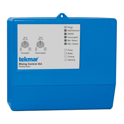
Tekmar Mixing Control 354 User manual

Tekmar

Tekmar Mixing Control 354 User manual

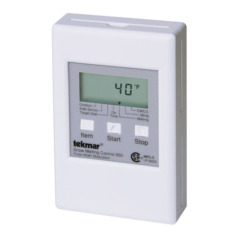
Tekmar D 650 User manual

Tekmar

Tekmar D 650 User manual

Tekmar House Control 401 User manual

Tekmar

Tekmar House Control 401 User manual

Tekmar tekmarNet 4 Setpoint Control 162 User manual

Tekmar

Tekmar tekmarNet 4 Setpoint Control 162 User manual

Tekmar tekmarNet 4 Setpoint Control 161 User manual

Tekmar

Tekmar tekmarNet 4 Setpoint Control 161 User manual

Tekmar 153 User manual

Tekmar

Tekmar 153 User manual

Tekmar 284 Use and care manual

Tekmar

Tekmar 284 Use and care manual

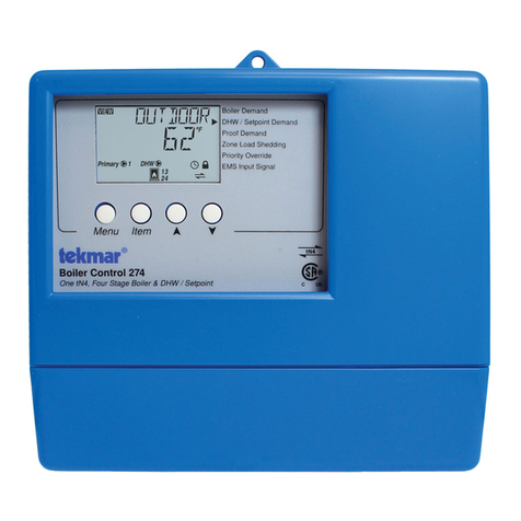
Tekmar 274 User manual

Tekmar

Tekmar 274 User manual

Tekmar 284 User manual

Tekmar

Tekmar 284 User manual

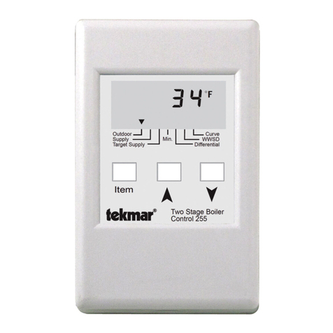
Tekmar D 255 User manual

Tekmar

Tekmar D 255 User manual

Tekmar Snow Melting Control 680 Use and care manual

Tekmar

Tekmar Snow Melting Control 680 Use and care manual

Popular Controllers manuals by other brands

Philips 9290 014 61062 installation guide

Philips

Philips 9290 014 61062 installation guide

BLEMO ER41 manual

BLEMO

BLEMO ER41 manual

McQuay MicroTech II Operation manual

McQuay

McQuay MicroTech II Operation manual

Siemens SIMATIC ET 200SP user manual

Siemens

Siemens SIMATIC ET 200SP user manual

Velleman CHLSC2 user manual

Velleman

Velleman CHLSC2 user manual

Photonic Universe AN Series user manual

Photonic Universe

Photonic Universe AN Series user manual

Emerson Fisher 657C instruction manual

Emerson

Emerson Fisher 657C instruction manual

Parker 6K8 installation guide

Parker

Parker 6K8 installation guide

maxon motor EPOS 24/1 Getting started

maxon motor

maxon motor EPOS 24/1 Getting started

National Instruments IC-3121 user manual

National Instruments

National Instruments IC-3121 user manual

Shinko ACS-13A-*A Series instruction manual

Shinko

Shinko ACS-13A-*A Series instruction manual

Roland BRIDGE CAST owner's manual

Roland

Roland BRIDGE CAST owner's manual

CALEFFI 161010 manual

CALEFFI

CALEFFI 161010 manual

GENERAL LIFE AC400 user manual

GENERAL LIFE

GENERAL LIFE AC400 user manual

Galcon AMC-6DC user guide

Galcon

Galcon AMC-6DC user guide

Cansec MAP1 Installation guides

Cansec

Cansec MAP1 Installation guides

Open House H571 user guide

Open House

Open House H571 user guide

Condair HP manual

Condair

Condair HP manual

manuals.online logo
manuals.online logoBrands
  • About & Mission
  • Contact us
  • Privacy Policy
  • Terms and Conditions

Copyright 2025 Manuals.Online. All Rights Reserved.