manuals.online logo
Brands
  1. Home
  2. •
  3. Brands
  4. •
  5. iNels
  6. •
  7. Controllers
  8. •
  9. iNels RFGB-20 User manual

iNels RFGB-20 User manual

RFGB-20, RFGB-40,
RFGB-220, RFGB-240
Glass touch controllers
EN
02-01/2021 Rev.0
Characteristics /
RFGB-20 RFGB-40 RFGB-220 RFGB-240
EN
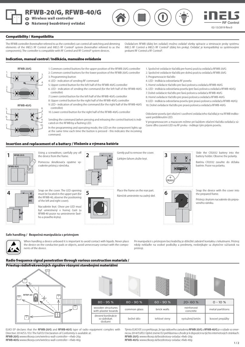
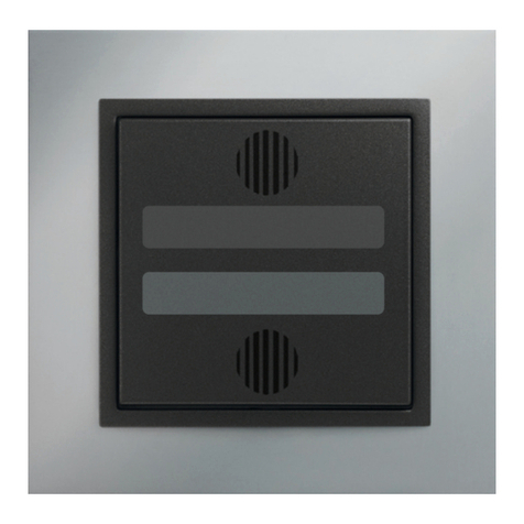
• The glass touch control is a design component of the RF Control system and is available in
an elegant black and white variant.
• Thickness only 8 mm.
• RFGB-20 / RFGB-220: 2 capacitive buttons allow you to control 2 components.
• RFGB-40 / RFGB-240: 4 capacitive buttons allow you to control 4 components.
• When the button is pressed, it sends the set command (ON / OFF, dimming, time off / on,
push/ pull). Transmission of the command is indicated by a red LED.
• Ability to set scenes where you control multiple iNELS RF Control devices with one press.
• The rear base allows screwing on the installation box, gluing with double-sided tape or just
laying on the table.
• Battery power supply (2x 3 V battery CR 2032 - part of the package) with a lifespan of
approx. 2 years depending on the frequency of use.
• Range up to 200 m (outdoors), in case of insufficient signal between the controller and the
device use the RFRP-20 signal repeater or devices with the RFIO2protocol that support this
function.
• Communication frequency with RFIO2protocol.
RF controlers can control:
• switches
RFSA-11B, RFSA-61B, RFSA-62B, RFSA-61M, RFSA-66M, RFSAI-61B, RFSC-11, RFSC-61, RFUS-11,
RFUS-61, RFJA-12B
• dimmers
RFDA-73/RGB, RFDA-11B, RFDA-71B, RFDEL-71B, RFDEL-71M, RFDSC-11, RFDSC-71, RFDAC-71B
• lighting
RF-RGB-LED-550, RF-White-LED-675
Control options /
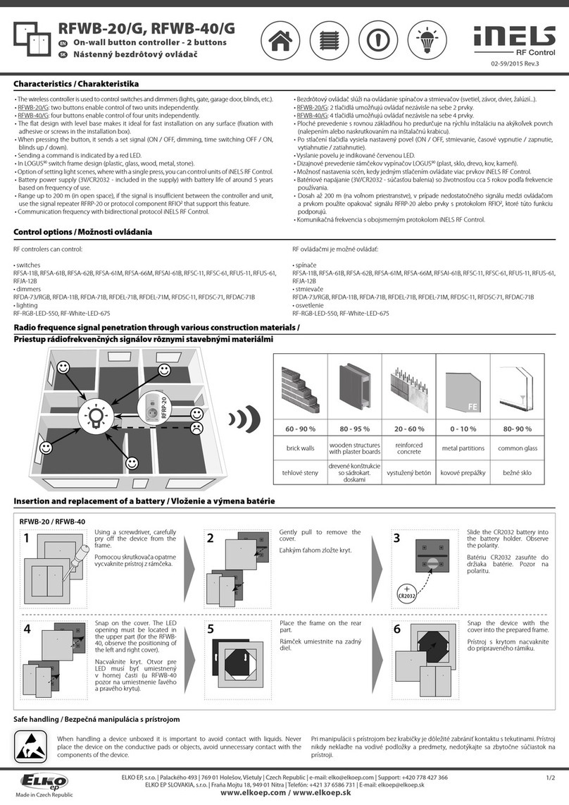
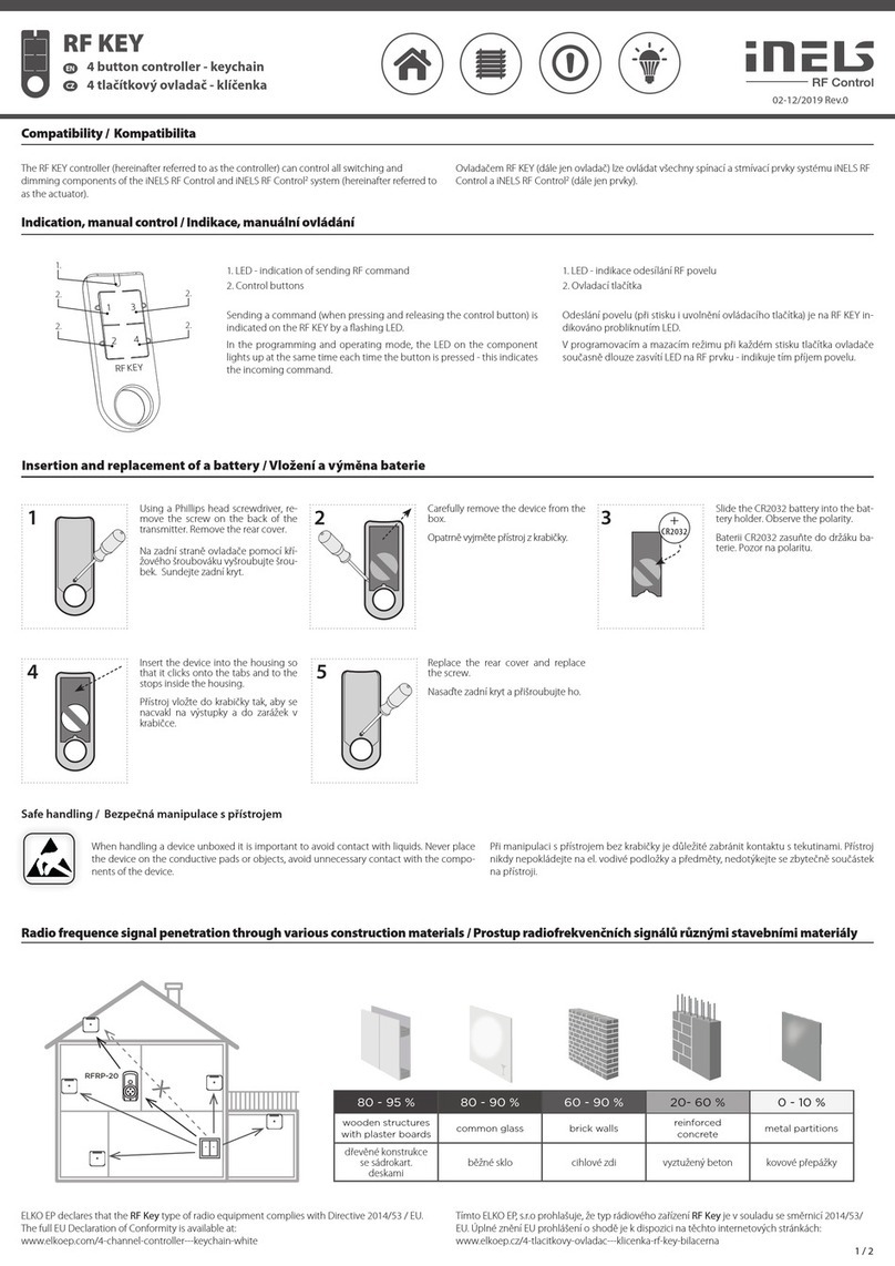
Radio frequence signal penetration through various construction materials /
x
RFRP-20
60 - 90 % 80 - 95 % 20 - 60 % 0 - 10 % 80- 90 %
brick walls wooden structures
with plaster boards
reinforced
concrete metal partitions common glass
1 /4
Controladores táctiles de cristal
ES
• El controlador táctil de cristal es un elemento de diseño del sistema RF Control y está
disponible en una elegante variante en blanco y negro.
• Espesor tan solo 8 mm.
• RFGB-20: 2 botones capacitivos permiten controlar 2 unidades.
• RFGB-40: 4 botones capacitivos permiten controlar 4 unidades.
• Después de presionar el botón, envía una orden de ajuste (ON / OFF, atenuación, apagado
/ encendido temporizado, subir / bajar). La transmisión de la orden se indica mediante un
LED rojo.
• Posibilidad de configurar escenas en las que puede controlar más unidades de iNELS RF
Control con una sola pulsación.
• La base trasera permite atornillar la caja de instalación, pegar con cinta de doble cara o
simplemente colocar sobre la mesa.
• Alimentación por pila (2x 3V CR2032 - parte del paquete) con una vida útil de
aproximadamente 2 años dependiendo de la frecuencia de uso.
• Alcance de hasta 200 mts (al aire libre), en caso de señal insuficiente entre controlador y la
unidad se puede utilizar el repetidor RFRP-20 o unidades con protocolo RFIO2, las cuales
tienen esta función.
• Frecuencia de comunicación con protocolo iNELS RF Control.
Con controlador RF se pueden controlar:
• conmutadores
RFSA-11B, RFSA-61B, RFSA-62B, RFSA-61M, RFSA-66M, RFSAI-61B, RFSC-11, RFSC-61, RFUS-11,
RFUS-61, RFJA-12B
• reguladores
RFDA-73/RGB, RFDA-11B, RFDA-71B, RFDEL-71B, RFDEL-71M, RFDSC-11, RFDSC-71, RFDAC-71B
• iluminación
RF-RGB-LED-550, RF-White-LED-675
Característica
Steuerungsoptionen
Transmisión de señales de radiofrecuencia en varios materiales de la construcción
pared de ladrillo estructuras de
madera con placas
de yeso hormigón armado chapas
metálicas vidrio normal
CR2032
+
CR2032
+
Mounting jig (with brackets) - 1x
Battery*- 2x
* Batteries are inserted in the product. Before
using for the first time, remove the insulating
tape from the battery contacts by pulling in
the direction of the arrow.
Double-sided adhesive label - 4x
Package contents /
Screws- 2x
After inserting the battery, the red LED lights up continuously for 3 seconds and then for 5
seconds, the selected controller function is indicated by flashing LED.
• double flash - standard RFIO2operating mode
• rapid flashing - mode of compatibility with older actuators
If you do not want to change the function of the controller, you must not press any buttons
during this time
To switch between RFIO2mode and compatibility mode:
If you need to change the operating mode of the controller, after inserting the battery, when
the LED is constantly lit. press buttons 1 and 2 simultaneously and hold until the LED starts to
signal the changed mode (double flash or rapid flash). Then the buttons must be released. The
selected function mode is stored in memory and after replacing the battery, the controller
continues to operate in the same mode.
If the controller is used in RFIO2mode, then it is necessary to instruct the controller and link to
the actuators switch to learn mode not only the actuator (according to the instructions for the
actuator), but also the controller in the following way: Remove the battery from the controller,
press some of the buttons several times to discharge the internal capacitors and replace the
battery. When the LED lights up, press button 1 and keep it pressed until the controller starts
signaling the learning mode with short flashing LEDs. Then release the button and the button
now works in RFIO2learning mode. To end the learning mode, remove the battery, press some
of the buttons several times and then replace the battery. Now we do not press any button and
the controller will start again in RFIO2operating mode.
Indicators, settings /
Insertion and replacement of a battery /
1CR2032
+
CR2032
+
2
1
CR2032
CR2032
2
CR2032
3
Press to open the plug-in battery
holder (you can use a flat-blade
screwdriver to open it).
Insert the CR2032 battery into
Battery holder. Watch out for
polarity.
Insert the holder into the device.
or /
CR2032
+
CR2032
+
3
Never mix new and old batteries when replacing! It is always necessary to replace both
batteries at the same time with new ones
2 / 4
Contenidos del paquete
Cinta de doble cara - 4x
Plantilla de montaje (con soportes) - 1x
Pila* - 2x
* Las baterías están insertadas en el producto.
Antes de usarlo por primera vez, retire la cinta
aislante de los contactos de la batería tirando a
la dirección de la fl echa
Tornillo- 2x
Después de insertar la batería, el LED rojo se enciende continuamente durante 3 segundos y
luego durante 5 segundos la función del controlador seleccionada se indica mediante un LED
parpadeante.
• Parpadeo doble - modo de funcionamiento estándar RFIO2
• Parpadeo rápido - modo de compatibilidad con actuadores de la generación anterior.
Si no queremos cambiar la función del controlador, no debemos presionar ningún botón durante
este tiempo.
Para cambiar entre el modo RFIO2y el modo de compatibilidad: Si necesitamos cambiar el modo
de funcionamiento del controlador, después de insertar la batería, cuando el LED está encendido
continualmente, pulsamos los botones 1 y 2 al mismo tiempo y lo mantenemos hasta que el
LED comience a señalar el modo cambiado (parpadeo doble o parpadeo rápido). Después
necesitamos soltar los botones. El modo de función seleccionado se almacena en la memoria
y después de reemplazar la batería, el controlador continúa funcionando en el mismo modo.
Si el controlador se usa en el modo RFIO2, entonces para asignar el controlador a los actuadores
es necesario cambiar el modo no solo en el actuador (de acuerdo con las instrucciones para
el actuador), sino también en el controlador de la siguiente manera: Retiramos la batería del
controlador y pulsamos los botones varias veces para descargar los condensadores internos y
volvemos a insertar la batería. En el momento en que se enciende el LED pulsamos el botón 1
y lo mantenemos pulsado hasta que el controlador empieza a señalar el modo de aprendizaje
mediante un breve parpadeo del LED. Luego soltamos la entrada y el controlador ahora
funciona en modo de aprendizaje RFIO2. Para fi nalizar el modo de aprendizaje, retiramos la
batería, pulsamos alguno de los botones varias veces y luego volvemos a insertar la batería. En
este momento no activamos ninguna entrada y el convertidor vuelve a arrancar en el modo de
funcionamiento RFIO2.
Indicación, confi guración
Insertary cambiar la pila
Inserte la batería CR2032 en el
soporte de la batería. Preste
atención a la polaridad
Presione el soporte de la
batería enchufable para abrir
(puede usar un destornillador
de punta plana para abrirlo).
Deslice el soporte al dispositivo.
o
Nunca mezcle baterías nuevas y viejas cuando las reemplace! Siempre es necesario re-
emplazar ambas baterías al mismo tiempo por otras nuevas.
Technical parameters /
More detailed information can be found in the iNELS RF Control Installation Manual:
https://www.elkoep.com/catalogs-and-brochures
ELKO EP, sro hereby declares that the type of radio equipment RFGB-20, RFGB-40,
RFGB-220, RFGB-240 is in accordance with Directives 2014/53 / EU, 2011/65 / EU,
2015/863 / EU and 2014 / 35 / EU. The full text of the EU Declaration of Conformity is
available on the following websites:
www.elkoep.com/glass-touch-controllers-white-sharp-rfgb-20w
www.elkoep.com/glass-touch-controller---2-buttons-black-sharp-rfgb-20b
www.elkoep.com/glass-touch-controller---4-buttons-white-sharp-rfgb-40w
www.elkoep.com/glass-touch-controller-4-buttons-black-sharp-rfgb-40b
www.elkoep.com/glass-touch-controller---2-buttons-white-round--rfgb-220w
www.elkoep.com/glass-touch-controller---2-buttons-black-round-rfgb-220b
www.elkoep.com/glass-touch-controller---4-buttons-white-round-rfgb-240w
www.elkoep.com/glass-touch-controller---4-buttons-black-round-rfgb-240b
When handling a device unboxed it is important to avoid contact with
liquids. Never place the device on the conductive pads or objects, avoid
unnecessary contact with the components of the device.
Safe handling /
Attention:
When you instal iNELS RF Control system, you have to keep
minimal distance 1 cm between each units. Between the
individual commands must be an interval of at least 1s.
Instruction manual is designated for mounting and also for user of the device. It is always a
part of its packing. Installation and connection can be carried out only by a person with ad-
equate professional qualification upon understanding this instruction manual and functions
of the device, and while observing all valid regulations. Trouble-free function of the device
also depends on transportation, storing and handling. In case you notice any sign of damage,
deformation, malfunction or missing part, do not install this device and return it to its seller.
It is necessary to treat this product and its parts as electronic waste after its lifetime is termi-
nated. Before starting installation, make sure that all wires, connected parts or terminals are
de-energized. While mounting and servicing observe safety regulations, norms, directives and
professional, and export regulations for working with electrical devices. Do not touch parts of
the device that are energized - life threat. Due to transmissivity of RF signal, observe correct
location of RF components in a building where the installation is taking place. RF Control is
designated only for mounting in interiors. The must not be installed into metal switchboards
and into plastic switchboards with metal door - transmissivity of RF signal is then impossible.
RF Control is not recommended for pulleys etc. - radiofrequency signal can be shielded by
an obstruction, interfered, battery of the transceiver can get flat etc. and thus disable remote
control.
Warning /
Power voltage:
Battery life:
Transmission indication:
Number of capacitive buttons:
Communication Protocal:
Frequence:
Signal transmission method:
Range:
Other data
Operating Temprature:
Working Position:
Mounting:
Protection:
Pollution degree:
Dimension:
Weight:
Related standards:
RFGB-20 RFGB-40 RFGB-220 RFGB-240
3 / 4
Especifi caciones técnicas
Tensiónde alimentación:
Vida de pilas:
Indicaciónde transmisión:
Número de botones:
Protocolode comunicación:
Frecuencia:
Modo de transmisiónde:
Alcance:
Más información
Temperatura de funcionamiento:
Posiciónde funcionamiento:
Montaje:
Protección:
Grado de contaminación:
Dimensiones:
Peso:
Normas conexas:
Advertencia:
En la instalación de iNELS RF Control debe haber una distancia
mínima entre las diferentes unidades de un centímetro. Entre
los diferentes ordenes debe pasar al menos 1s.
2x 3 Vbattery CR 2032/ 2x pilaCR 2032
about2years depending onthe frequency of use/ aproximadamente 2añosdependiendo delafrecuenciadeuso
Red LED/ rojoLED
24 24
RFIO
866–922 MHz
one-way addressed message/ mensajedirigida unidireccionalmente
in the open up to 200 m/ de hasta 200 mts (al aire libre)
-10 ... +50 °C
any / cualquiera
adhesive, screw / pegado, atornillados
IP20
2
94 x 94 x 8mm 100 x 100 x 8mm
122 g 122 g 122 g 122 g
EN 60669, EN 300 220, EN 301 489 RTTE Directive,NVNo. 426/2000 Coll.(Directive 1999 / EC),
EN 60669, EN 300 220, EN 301 489 norma RTTE, NVč.426/2000Sb(norma 1999/ES)
El manual de uso está dirigido para la instalación y el usuario del dispositivo. Manual siempre
está incluido en embalaje. La instalación y conexión puede realizar sólo personal con adecuadas
cualifi caciones profesionales, de conformidad con todas las regulaciones aplicadas, y que está
perfectamente familiarizado con estas instrucciones y funciones del dispositivo. Función del
dispositivo también depende del transporte, almacenamiento y la manipulación. Si se observa
cualquier signo de daño, deformación, mal funcionamiento o pieza que falta, no instale este producto
y devolvelo al vendedor. Con el producto y sus componentes debe ser tratado después de su vida
útil como con residuos electrónicos. Antes de iniciar la instalación, asegúrese de que todos los cables,
partes o terminales conectados están sin la conexión a la red. En el montaje y el mantenimiento se
deben observar las normas de seguridad, normas, directivas y reglamentos para trabajar con equipos
eléctricos. No toque las partes del dispositivo que están conectadas en la red - puede producir peligro
de vida. Debido a la transmisibilidad de la señal RF, observe la correcta ubicación de los componentes
RF en un edifi cio donde la instalación se lleva a cabo. RF Control está diseñado para montaje en
interiores, las unidades no están diseñados para la instalación en exteriores y espacios húmedos, no
se pueden instalar en cuadros eléctricos de metal y en cuadros eléctricos plásticos con puerta de
metal - lo que empeora transmisividad de la señal RF. RF Control no se recomienda para el control
de dispositivos que ofrecen funciones vitales o para controlar dispositivos tales como bombas, el.
calentadores sin termostato, ascensores, montacargas, etc. - Señal de radiofrecuencia puede estar
bloqueado por una obstrucción, interferida, la batería del controlador puede estar ya sin energía, etc.
y por lo tanto el control remoto puede ser incapacitado.
Advertencia
Al manipular con el dispositivo sin embalaje es importante evitar el contacto con líquidos.
Nunca ponga el dispositivo sobre objetos conductores, no toque los componentes en el
dispositivo de forma innecesaria.
Manipulación segura con el dispositivo
1 3
2
Push the brackets out of the
mounting fixture.
Assembly /
Push the holders into the holes.
Free tting /
1 32
Peel off one protective layer on
the doublesided adhesive she-
ets and stick them to the marked
places on the controller.
Peel off the second protective
layer on the double-sided
adhesive sheets and place the
control in the prepared place.
Adhesive /
Depending on the type of sur-
face, clean (remove dust or de-
grease) the place where you
want to place the controller.
13
Place the mounting jig on the
KU box and screw it on.
Screw /
Snap on the controller.
Made in Czech Republic
2
ELKO EP, s.r.o. | Palackého 493 | 769 01 | Holešov, Všetuly | Czech Republic | e-mail: [email protected] | Support: +420 778 427 366
ELKO EP ESPAÑA, S.L. | C/ Josep Martinez 15a, bj | 07007 Palma de Mallorca | e-mail: [email protected] | Tel.: +34 971 751 425 | Fax: +34 971 428 076
Empuje los soportes fuera del
dispositivo de montaje.
Empuje los soportes en los
agujeros.
Montaje
Sueltos
Despegue una capa protectora
de las hojas adhesivas de doble
cara y péguelas en los lugares
marcados en el controlador.
Según el tipo de superfi cie,
limpie (quite el polvo o
desengrase) el lugar donde
desee colocar el mando a
distancia.
Retire la segunda capa protectora
de las hojas adhesivas de doble
cara y coloque el controlador en el
lugar preparado.
Coloque la plantilla de montaje
en la caja KU y atorníllela.
Atornillado
Coloca el controlador.
Pegando
www.elkoep.com / www.elkoep.es

This manual suits for next models

3

Other iNels Controllers manuals

iNels SA2-04M Simple manual

iNels

iNels SA2-04M Simple manual

iNels RFWB-20/G User manual

iNels

iNels RFWB-20/G User manual

iNels RFWB-20/G User manual

iNels

iNels RFWB-20/G User manual

iNels RFWB-20/G User manual

iNels

iNels RFWB-20/G User manual

iNels RFDEL-76M User manual

iNels

iNels RFDEL-76M User manual

iNels SA3-06M User manual

iNels

iNels SA3-06M User manual

iNels RFWB-20/G User manual

iNels

iNels RFWB-20/G User manual

iNels IM2-140M Simple manual

iNels

iNels IM2-140M Simple manual

iNels RF KEY - 40 User manual

iNels

iNels RF KEY - 40 User manual

iNels RFWB-20/G User manual

iNels

iNels RFWB-20/G User manual

iNels RF KEY User manual

iNels

iNels RF KEY User manual

iNels RF KEY User manual

iNels

iNels RF KEY User manual

iNels WTC2-21 Simple manual

iNels

iNels WTC2-21 Simple manual

iNels RF KEY-40 User manual

iNels

iNels RF KEY-40 User manual

iNels RFWB-20/G User manual

iNels

iNels RFWB-20/G User manual

iNels RFDA-73M/RGB User manual

iNels

iNels RFDA-73M/RGB User manual

iNels SA2-01B Simple manual

iNels

iNels SA2-01B Simple manual

iNels SA3-012M User manual

iNels

iNels SA3-012M User manual

iNels JA2-02B User manual

iNels

iNels JA2-02B User manual

iNels RFWB-20/G User manual

iNels

iNels RFWB-20/G User manual

iNels RFWB-20/G User manual

iNels

iNels RFWB-20/G User manual

iNels GSB3-40 User manual

iNels

iNels GSB3-40 User manual

iNels RFWB-20/G User manual

iNels

iNels RFWB-20/G User manual

iNels IDRT3-1 User manual

iNels

iNels IDRT3-1 User manual

Popular Controllers manuals by other brands

ST UM2520 user manual

ST

ST UM2520 user manual

HIMA HIMatrix F20 manual

HIMA

HIMA HIMatrix F20 manual

TB Controls TC02 Operation & maintenance manual

TB Controls

TB Controls TC02 Operation & maintenance manual

dunkermotoren ServoTube 25 instruction manual

dunkermotoren

dunkermotoren ServoTube 25 instruction manual

Azatrax SHS installation guide

Azatrax

Azatrax SHS installation guide

Xylem HYDROVAR HV2.1f operating instructions

Xylem

Xylem HYDROVAR HV2.1f operating instructions

Coolmay CX3G-32M Programming manual

Coolmay

Coolmay CX3G-32M Programming manual

IFM DX2011 manual

IFM

IFM DX2011 manual

Carel ir33+ wide VCC quick start guide

Carel

Carel ir33+ wide VCC quick start guide

EFI Fiery Configuration and setup

EFI

EFI Fiery Configuration and setup

Newport i8-AL Operator's manual

Newport

Newport i8-AL Operator's manual

Savant SmartControl 3 Quick reference guide

Savant

Savant SmartControl 3 Quick reference guide

Channel Vision TE-111 instructions

Channel Vision

Channel Vision TE-111 instructions

Haiwell PLC user manual

Haiwell

Haiwell PLC user manual

Curtis 1220 manual

Curtis

Curtis 1220 manual

PI N470 Series user manual

PI

PI N470 Series user manual

NAiS GT10 Technical manual

NAiS

NAiS GT10 Technical manual

TTL TWICS user manual

TTL

TTL TWICS user manual

manuals.online logo
manuals.online logoBrands
  • About & Mission
  • Contact us
  • Privacy Policy
  • Terms and Conditions

Copyright 2025 Manuals.Online. All Rights Reserved.