© 2012 557_D - 08/12
2 of 48
A Watts Water Technologies Company
Congratulations on the purchase of your new tekmar®thermostat.
This manual will step through the complete installation, programming and sequence
of operation for this control. At the back, there are tips for control and system
troubleshooting.
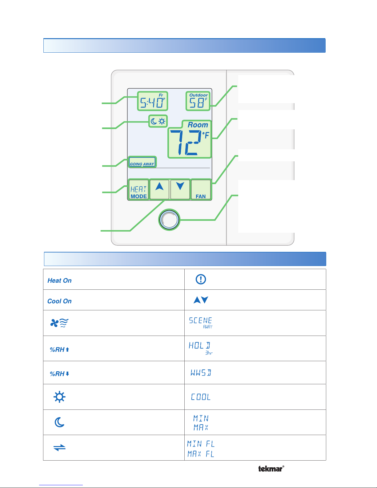
Getting Started
Table of Contents
Getting Started ...............................2
Installation ...........................................3
Caution............................................3
Preparation .....................................3
Removing The Wiring Cover...........3
Mounting The Thermostat...............4
Thermostat Wiring ..........................4
Compatible Sensors .......................5
Testing the Thermostat Wiring........5
Switch Settings....................................6
User Interface......................................7
Home Screen..................................7
Symbols Description.......................7
Programmable Settings.......................8
Programming Menus ......................8
Set Temp Menu..........................9-12
Time Menu............................... 12-13
Schedule Menu........................14-15
Display Menu ...........................15-16
Scenes Menu................................16
Monitor Menu...........................17-21
Toolbox Menu ..........................21-23
Setup Menu............................. 24-30
Sequence of Operation......................31
Heating Operation.........................31
Cooling Operation.........................32
Room Min and Max Limits ............33
Hydronic Pump / Valve Operation ....34
Fan Operation...............................34
Relative Humidity Operation.........35
Air Group Operation......................37
Time Clock....................................37
Temperature Adjustment ..............38
Programmable Schedules ............39
Scenes (System Override)............40
Secondary Temperature Display...41
Access Levels...............................42
tekmarNet®Address .....................42
Cleaning the Thermostat ..............42
Troubleshooting .................................43
Error Messages ...................... 43-47
Technical Data ..............................47
Limited Warranty and Product
Return Procedure .........................48